Page 1319 of 4592

P20769
Vehicle Speed
60 ~ 80 km/h
(38 ~ 50 mph)
Idling
IG SW OFF
(1)(2)
Warm up
3 ~ 5 min.2 min.
3 ~ 5 min.Time (3)
(4)
(5)(6)
(7)
2 min.
± DIAGNOSTICSENGINE (5S±FE)
DI±107
342 Author�: Date�:
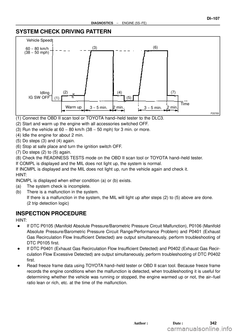
SYSTEM CHECK DRIVING PATTERN
(1) Connect the OBD II scan tool or TOYOTA hand±held tester to the DLC3.
(2) Start and warm up the engine with all accessories switched OFF.
(3) Run the vehicle at 60 ~ 80 km/h (38 ~ 50 mph) for 3 min. or more.
(4) Idle the engine for about 2 min.
(5) Do steps (3) and (4) again.
(6) Stop at safe place and turn the ignition switch OFF.
(7) Do steps (2) to (5) again.
(8) Check the READINESS TESTS mode on the OBD II scan tool or TOYOTA hand±held tester.
If COMPL is displayed and the MIL does not light up, the system is normal.
If INCMPL is displayed and the MIL does not light up, run the vehicle again and check it.
HINT:
INCMPL is displayed when either condition (a) or (b) exists.
(a) The system check is incomplete.
(b) There is a malfunction in the system.
If there is a malfunction in the system, the MIL will light up after steps (2) to (5) above are done.
(2 trip detection logic)
INSPECTION PROCEDURE
HINT:
�If DTC P0105 (Manifold Absolute Pressure/Barometric Pressure Circuit Malfunction), P0106 (Manifold
Absolute Pressure/Barometric Pressure Circuit Range/Performance Problem) and P0401 (Exhaust
Gas Recirculation Flow Insufficient Detected) are output simultaneously, perform troubleshooting of
DTC P0105 first.
�If DTC P0401 (Exhaust Gas Recirculation Flow Insufficient Detected) and P0402 (Exhaust Gas Recir-
culation Flow Excessive Detected) are output simultaneously, perform troubleshooting of DTC P0402
first.
�Read freeze frame data using TOYOTA hand±held tester or OBD II scan tool. Because freeze frame
records the engine conditions when the malfunction is detected, when troubleshooting it is useful for
determining whether the vehicle was running or stopped, the engine warmed up or not, the air±fuel
ratio lean or rich, etc. at the time of the malfunction.
Page 1321 of 4592
± DIAGNOSTICSENGINE (5S±FE)
DI±109
344 Author�: Date�:
4 Check EGR system (See page EC±12).
NG Repair or replace.
OK
5 Check EGR vacuum modulator (See page EC±12).
NG Repair or replace.
OK
6 Check EGR valve (See page EC±12).
NG Repair or replace.
OK
7 Check manifold absolute pressure sensor (See page SF±53).
NG Repair or replace.
OK
Check and replace ECM (See page IN±31).
Page 1324 of 4592
DI±112
± DIAGNOSTICSENGINE (5S±FE)
347 Author�: Date�:
7 Check manifold absolute pressure sensor (See page SF±53).
NG Repair and replace.
OK
Check and replace ECM (See page IN±31).
Page 1325 of 4592

± DIAGNOSTICSENGINE (5S±FE)
DI±113
348 Author�: Date�:
DTC P0402 Exhaust Gas Recirculation Flow Excessive
Detected
CIRCUIT DESCRIPTION
Refer to DTC P0401 (Exhaust Gas Recirculation Flow Insufficient Detected) on page DI±105.
DTC No.DTC Detecting ConditionTrouble Area
P0402
After engine is warmed up, conditions (a) and (b) continue:
(a) Intake manifold absolute pressure is larger than value cal-
culated by ECM while EGR system is ON
(b) Misfiring is detected during idling
(2 trip detection logic)�EGR valve stuck open
�Vacuum or EGR hose is connected to wrong post
�Manifold absolute pressure sensor
�ECM
WIRING DIAGRAM
Refer to DTC P0401 (Exhaust Gas Recirculation Flow Insufficient Detected) on DI±105.
SYSTEM CHECK DRIVING PATTEM
Refer to DTC P0401 (Exhaust Gas Recirculation Flow Insufficient Detected) on DI±105.
INSPECTION PROCEDURE
HINT:
�If DTC P0105 (Manifold Absolute Pressure/Barometric Pressure Circuit Malfunction), P0106 (Manifold
Absolute Pressure/Barometric Pressure Circuit Range/Performance Problem) and P0402 (Exhaust
Gas Recirculation Flow Excessive Detected) are output simultaneously, perform troubleshooting of
DTC P0105 first.
�If DTC P0401 (Exhaust Gas Recirculation Flow Insufficient Detected) and P0402 (Exhaust Gas Recir-
culation Flow Excessive Detected) are output simultaneously, perform troubleshooting of DTC P0402
first.
�Read freeze frame data using TOYOTA hand±held tester or OBD II scan tool. Because freeze frame
records the engine conditions when the malfunction is detected, when troubleshooting it is useful for
determining whether the vehicle was running or stopped, the engine warmed up or not, the air±fuel
ratio lean or rich, etc. at the time of the malfunction.
1 Check connection of vacuum hose and EGR hose (See page EC±12).
NG Repair or replace.
OK
DI016±04
Page 1327 of 4592
± DIAGNOSTICSENGINE (5S±FE)
DI±115
350 Author�: Date�:
6 Check EGR vacuum modulator (See page EC±12).
NG Repair or replace.
OK
7 Check manifold absolute pressure sensor (See page SF±53).
NG Repair or replace.
OK
Check and replace ECM (See page IN±31).
Page 1704 of 4592
DI03B±02
ABS Check Sheet
Inspector 's
Name:
Customer 's Name
Date Vehicle
Brought InRegistration Year Registration No.
Frame No.
Odometer Reading/ /
/ /
Date Problem First Occurred
Frequency Problem Occurs/ /
ContinuousIntermittent ( times a day)
Remains ONDoes not Light Up
DTC Check1st Time
2nd TimeNormal Code
Malfunction Code (Code )
Normal CodeMalfunction Code (Code )
Symptomskm
miles
ABS does not operate.
ABS Warning Light
AbnormalABS does not operate efficiently. DI±492
± DIAGNOSTICSANTI±LOCK BRAKE SYSTEM (DENSO Made)
727 Author�: Date�:
CUSTOMER PROBLEM ANALYSIS CHECK
Page 1705 of 4592

DI03C±03
F00047
F00006
DLC1Short Pin
S-17-1 Iei-23-1-A
F00041
DLC2 DLC1
Tc E1
E1Tc
R01346
Normal Code
0.25 sec.
0.25 sec. 2 sec.
ON
OFF
ON
OFF0.5 sec. 0.5 sec.
Code 11 and 21
4 sec.1.5 sec.
2.5 sec.
Code 11 Code 21
± DIAGNOSTICSANTI±LOCK BRAKE SYSTEM (DENSO Made)
DI±493
728 Author�: Date�:
PRE±CHECK
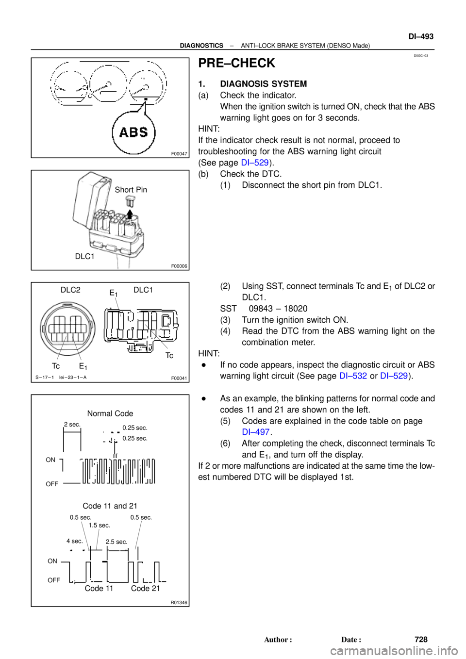
1. DIAGNOSIS SYSTEM
(a) Check the indicator.
When the ignition switch is turned ON, check that the ABS
warning light goes on for 3 seconds.
HINT:
If the indicator check result is not normal, proceed to
troubleshooting for the ABS warning light circuit
(See page DI±529).
(b) Check the DTC.
(1) Disconnect the short pin from DLC1.
(2) Using SST, connect terminals Tc and E
1 of DLC2 or
DLC1.
SST 09843 ± 18020
(3) Turn the ignition switch ON.
(4) Read the DTC from the ABS warning light on the
combination meter.
HINT:
�If no code appears, inspect the diagnostic circuit or ABS
warning light circuit (See page DI±532 or DI±529).
�As an example, the blinking patterns for normal code and
codes 11 and 21 are shown on the left.
(5) Codes are explained in the code table on page
DI±497.
(6) After completing the check, disconnect terminals Tc
and E
1, and turn off the display.
If 2 or more malfunctions are indicated at the same time the low-
est numbered DTC will be displayed 1st.
Page 1707 of 4592

F02201
DLC1
TsTc E1
BR3904
0.13 sec. 0.13 sec.
ON
OFF
BR3893
Malfunction Code (Example Code 72, 76)
72 67
ON
OFF
0.5 sec. 0.5 sec. 0.5 sec. 0.5 sec.1.5 sec.
2.5 sec.4 sec.
Repeat
± DIAGNOSTICSANTI±LOCK BRAKE SYSTEM (DENSO Made)
DI±495
730 Author�: Date�:
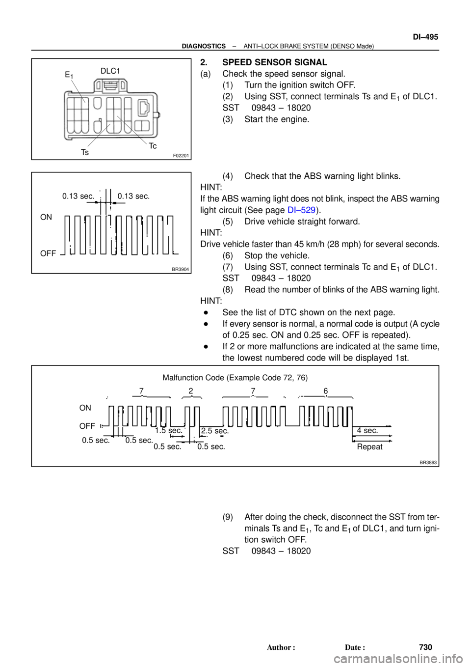
2. SPEED SENSOR SIGNAL
(a) Check the speed sensor signal.
(1) Turn the ignition switch OFF.
(2) Using SST, connect terminals Ts and E
1 of DLC1.
SST 09843 ± 18020
(3) Start the engine.
(4) Check that the ABS warning light blinks.
HINT:
If the ABS warning light does not blink, inspect the ABS warning
light circuit (See page DI±529).
(5) Drive vehicle straight forward.
HINT:
Drive vehicle faster than 45 km/h (28 mph) for several seconds.
(6) Stop the vehicle.
(7) Using SST, connect terminals Tc and E
1 of DLC1.
SST 09843 ± 18020
(8) Read the number of blinks of the ABS warning light.
HINT:
�See the list of DTC shown on the next page.
�If every sensor is normal, a normal code is output (A cycle
of 0.25 sec. ON and 0.25 sec. OFF is repeated).
�If 2 or more malfunctions are indicated at the same time,
the lowest numbered code will be displayed 1st.
(9) After doing the check, disconnect the SST from ter-
minals Ts and E
1, Tc and E1 of DLC1, and turn igni-
tion switch OFF.
SST 09843 ± 18020