Page 3214 of 4592

RS0EZ±01
H02267H02268H08322
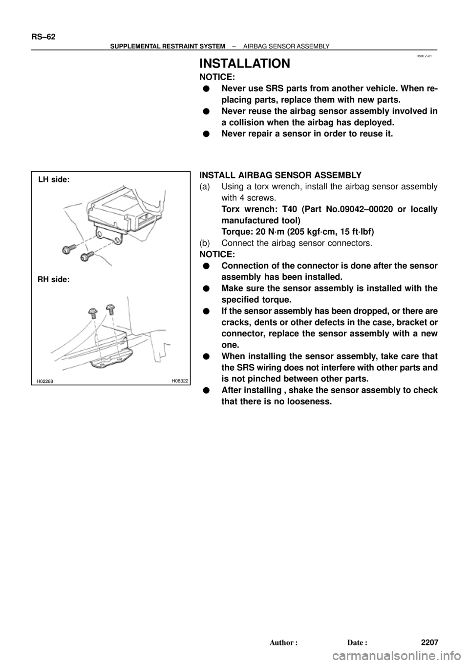
LH side:
RH side: RS±62
± SUPPLEMENTAL RESTRAINT SYSTEMAIRBAG SENSOR ASSEMBLY
2207 Author�: Date�:
INSTALLATION
NOTICE:
�Never use SRS parts from another vehicle. When re-
placing parts, replace them with new parts.
�Never reuse the airbag sensor assembly involved in
a collision when the airbag has deployed.
�Never repair a sensor in order to reuse it.
INSTALL AIRBAG SENSOR ASSEMBLY
(a) Using a torx wrench, install the airbag sensor assembly
with 4 screws.
Torx wrench: T40 (Part No.09042±00020 or locally
manufactured tool)
Torque: 20 N´m (205 kgf´cm, 15 ft´lbf)
(b) Connect the airbag sensor connectors.
NOTICE:
�Connection of the connector is done after the sensor
assembly has been installed.
�Make sure the sensor assembly is installed with the
specified torque.
�If the sensor assembly has been dropped, or there are
cracks, dents or other defects in the case, bracket or
connector, replace the sensor assembly with a new
one.
�When installing the sensor assembly, take care that
the SRS wiring does not interfere with other parts and
is not pinched between other parts.
�After installing , shake the sensor assembly to check
that there is no looseness.
Page 3215 of 4592
RS01L±14
H08233
N´m (kgf´cm, ft´lbf) : Specified torqueFront Airbag Sensor (RH)Front Airbag Sensor (LH)
20 (205, 15)
20 (205, 15)
20 (205, 15)
Turn Signal Light RH
Turn Signal Light LH
Head Light RH
Head Light LH
± SUPPLEMENTAL RESTRAINT SYSTEMFRONT AIRBAG SENSOR
RS±63
2208 Author�: Date�:
FRONT AIRBAG SENSOR
COMPONENTS
Page 3219 of 4592

RS01P±14
H06728
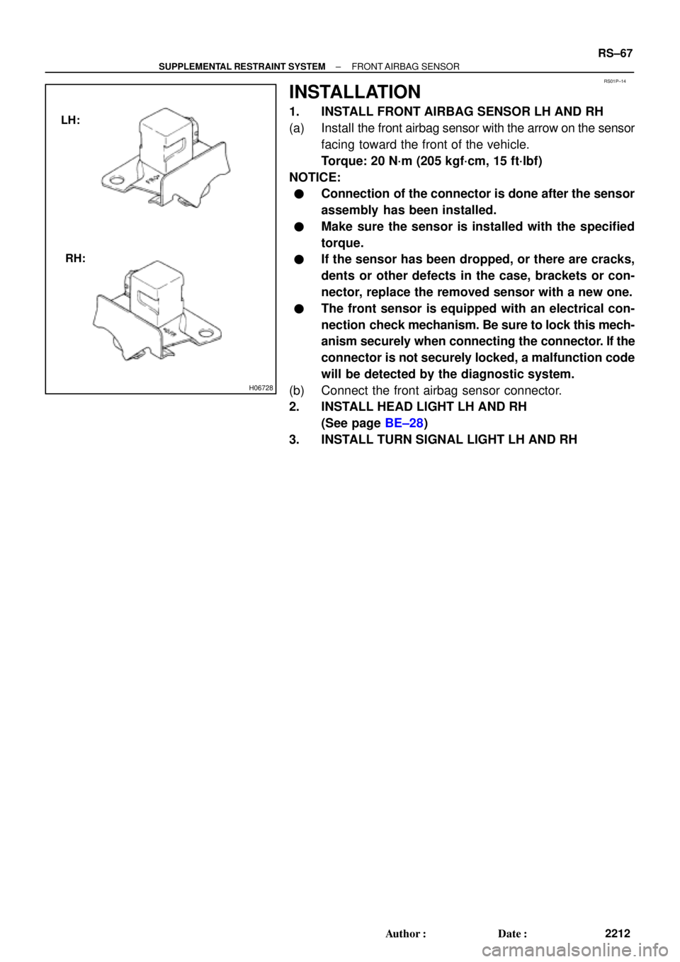
LH:
RH:
± SUPPLEMENTAL RESTRAINT SYSTEMFRONT AIRBAG SENSOR
RS±67
2212 Author�: Date�:
INSTALLATION
1. INSTALL FRONT AIRBAG SENSOR LH AND RH
(a) Install the front airbag sensor with the arrow on the sensor
facing toward the front of the vehicle.
Torque: 20 N´m (205 kgf´cm, 15 ft´lbf)
NOTICE:
�Connection of the connector is done after the sensor
assembly has been installed.
�Make sure the sensor is installed with the specified
torque.
�If the sensor has been dropped, or there are cracks,
dents or other defects in the case, brackets or con-
nector, replace the removed sensor with a new one.
�The front sensor is equipped with an electrical con-
nection check mechanism. Be sure to lock this mech-
anism securely when connecting the connector. If the
connector is not securely locked, a malfunction code
will be detected by the diagnostic system.
(b) Connect the front airbag sensor connector.
2. INSTALL HEAD LIGHT LH AND RH
(See page BE±28)
3. INSTALL TURN SIGNAL LIGHT LH AND RH
Page 3220 of 4592
RS01Q±06
H03285: Specified torqueN´m (kgf´cm, ft´lbf)
Side Airbag Sensor Assembly
20 (205, 15)
Front Seat Outer Belt Retractor
42 (430, 31)
Center Pillar Lower Garnish
Front Door Scuff Plate
7.5 (76, 66 in.´lbf)
RS±68
± SUPPLEMENTAL RESTRAINT SYSTEMSIDE AIRBAG SENSOR ASSEMBLY
2213 Author�: Date�:
SIDE AIRBAG SENSOR ASSEMBLY
COMPONENTS
Page 3224 of 4592

RS05W±02
H01339
H01352
RS±72
± SUPPLEMENTAL RESTRAINT SYSTEMSIDE AIRBAG SENSOR ASSEMBLY
2217 Author�: Date�:
INSTALLATION
NOTICE:
�Never use SRS parts from another vehicle. When re-
placing parts, replace them with new ones.
�Never reuse the side airbag sensor assembly in-
volved in a collision when the airbag has deployed.
�Never repair a sensor in order to reuse it.
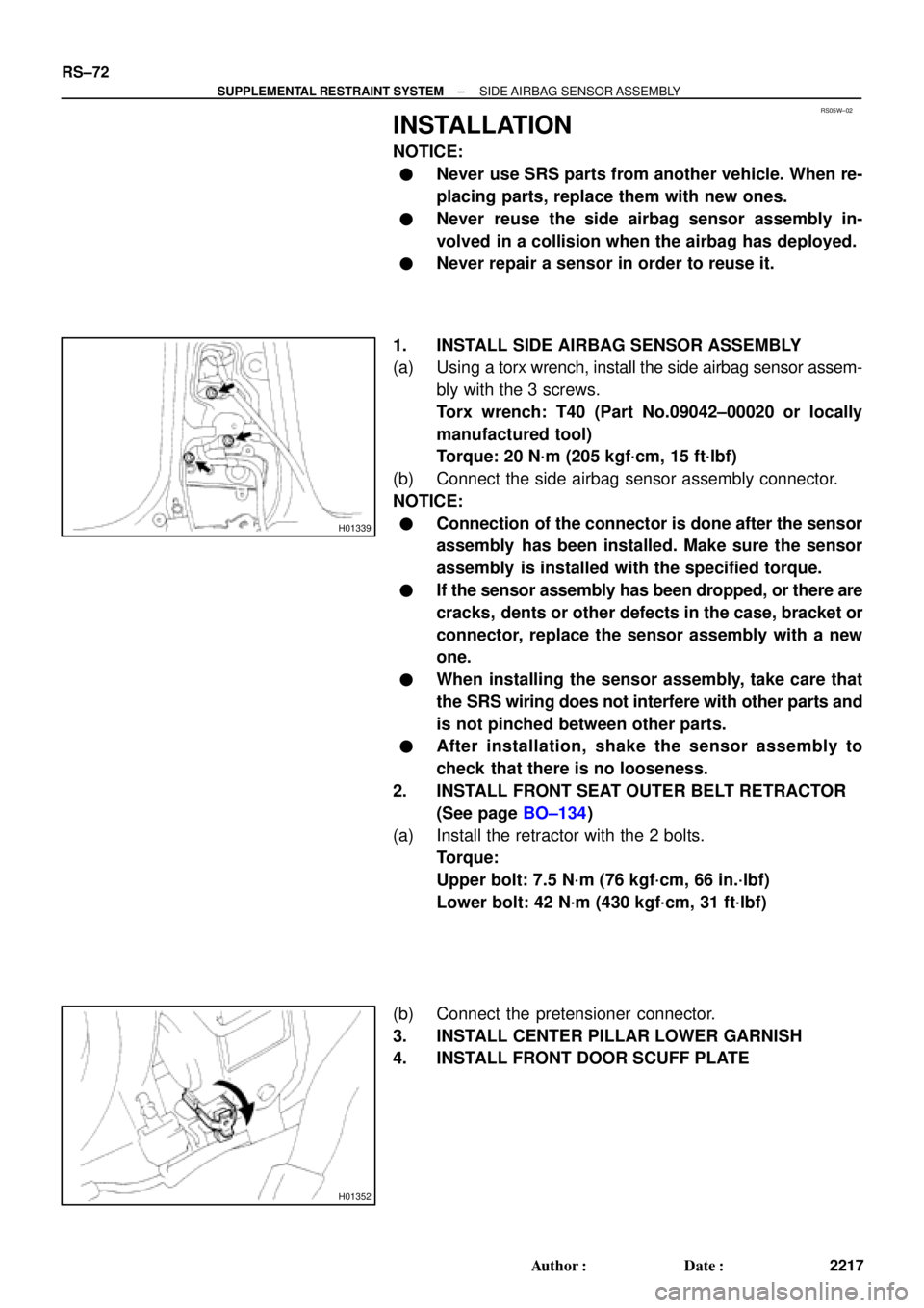
1. INSTALL SIDE AIRBAG SENSOR ASSEMBLY
(a) Using a torx wrench, install the side airbag sensor assem-
bly with the 3 screws.
Torx wrench: T40 (Part No.09042±00020 or locally
manufactured tool)
Torque: 20 N´m (205 kgf´cm, 15 ft´lbf)
(b) Connect the side airbag sensor assembly connector.
NOTICE:
�Connection of the connector is done after the sensor
assembly has been installed. Make sure the sensor
assembly is installed with the specified torque.
�If the sensor assembly has been dropped, or there are
cracks, dents or other defects in the case, bracket or
connector, replace the sensor assembly with a new
one.
�When installing the sensor assembly, take care that
the SRS wiring does not interfere with other parts and
is not pinched between other parts.
�After installation, shake the sensor assembly to
check that there is no looseness.
2. INSTALL FRONT SEAT OUTER BELT RETRACTOR
(See page BO±134)
(a) Install the retractor with the 2 bolts.
Torque:
Upper bolt: 7.5 N´m (76 kgf´cm, 66 in.´lbf)
Lower bolt: 42 N´m (430 kgf´cm, 31 ft´lbf)
(b) Connect the pretensioner connector.
3. INSTALL CENTER PILLAR LOWER GARNISH
4. INSTALL FRONT DOOR SCUFF PLATE
Page 3229 of 4592

SS0ZT±01
SS±2
± SERVICE SPECIFICATIONSSTANDARD BOLT
165 Author�: Date�:
SPECIFIED TORQUE FOR STANDARD BOLTS
Specified torque
ClassDiameter
mm
Pitch
mmHexagon head boltHexagon flange boltClassmmmmN´mkgf´cmft´lbfN´mkgf´cmft´lbf
4T
6
8
10
12
14
161
1.25
1.25
1.25
1.5
1.55
12.5
26
47
74
11 555
130
260
480
760
1,15048 in.´lbf
9
19
35
55
836
14
29
53
84
±60
145
290
540
850
±52 in.´lbf
10
21
39
61
±
5T
6
8
10
12
14
161
1.25
1.25
1.25
1.5
1.56.5
15.5
32
59
91
14065
160
330
600
930
1,40056 in.´lbf
12
24
43
67
1017.5
17.5
36
65
100
±75
175
360
670
1,050
±65 in.´lbf
13
26
48
76
±
6T
6
8
10
12
14
161
1.25
1.25
1.25
1.5
1.58
19
39
71
11 0
17080
195
400
730
1,100
1,75069 in.´lbf
14
29
53
80
1279
21
44
80
125
±90
210
440
810
1,250
±78 in.´lbf
15
32
59
90
±
7T
6
8
10
12
14
161
1.25
1.25
1.25
1.5
1.510.5
25
52
95
145
23011 0
260
530
970
1,500
2,3008
19
38
70
108
16612
28
58
105
165
±120
290
590
1,050
1,700
±9
21
43
76
123
±
8T
8
10
121.25
1.25
1.2529
61
11 0300
620
1,10022
45
8033
68
120330
690
1,25024
50
90
9T
8
10
121.25
1.25
1.2534
70
125340
710
1,30025
51
9437
78
140380
790
1,45027
57
105
10T
8
10
121.25
1.25
1.2538
78
140390
800
1,45028
58
10542
88
155430
890
1,60031
64
11 6
11 T
8
10
121.25
1.25
1.2542
87
155430
890
1,60031
64
11 647
97
175480
990
1,80035
72
130
Page 3232 of 4592
SS075±01
± SERVICE SPECIFICATIONSMAINTENANCE
SS±5
168 Author�: Date�:
TORQUE SPECIFICATION
Part tightenedN´mkgf´cmft´lbf
Front seat mount bolts3737527
Front suspension member x Body1811,850134
Rear suspension member x Body5152038
Page 3236 of 4592

SS0AE±03
± SERVICE SPECIFICATIONSENGINE MECHANICAL (5S±FE)
SS±9
172 Author�: Date�:
TORQUE SPECIFICATION
Part tightenedN´mkgf´cmft´lbf
Oil pump pulley x Oil pump drive shaft2424518
No.2 idler pulley x Oil pump4242531
Crankshaft pulley x Crankshaft1081,10080
Camshaft timing pulley x Camshaft
for use with SST54
37550
38040
27
No.1 idler pulley x Cylinder head4242531
Cylinder head x Cylinder block 1st
2nd49
Turn 90°500
Turn 90°36
Turn 90°
Water bypass pipe x Cylinder head1919514
Spark plug tube x Cylinder head4950036
Camshaft bearing cap x Cylinder head1919014
Cylinder head cover x Cylinder head4445033
RH engine hanger x Generator bracket2525018
Generator bracket x Cylinder head4242531
LH engine hanger x Cylinder head2525018
No.3 timing belt cover x Cylinder head7.88069 in.´lbf
Delivery pipe x Cylinder head131309
Intake manifold x Cylinder head1919514
Fuel inlet hose x Delivery pipe
for use with SST34
29350
30025
21
EGR valve x intake manifold13.313010
EGR pipe x Cylinder head61.260045
Intake manifold stay x Intake manifold3939829
Intake manifold stay x Stiffening plate3939829
Water outlet x Cylinder head1515011
No.2 intake manifold stay x Cylinder head2121415
No.2 intake manifold stay x Intake manifold4242831
Exhaust manifold x Cylinder head4950036
No.1 exhaust manifold stay x Exhaust manifold4242531
No.1 exhaust manifold stay x Transaxle4242531
No.2 exhaust manifold stay x Exhaust manifold4242531
No.2 exhaust manifold stay, LH stiffener plate x Cylinder block TMC made
TMMK made58
42591
42543
31
No.1 rear end plate x Cylinder block9.39582 in.´lbf
Flywheel (M/T) x Crankshaft8890065
Drive plate (A/T) x Crankshaft8385061
Transaxle (M/T) x Cylinder block 14 mm head
17 mm head46
64470
65034
47
Transaxle (A/T) x Cylinder block6667048
Drive plate x Torque converter clutch2728020
No.2 rear end plate x Cylinder block9.39582 in.´lbf
Exhaust pipe bracket, No.2 rear end plate x Transaxle1919514
RH stiffener plate x Cylinder block3939829
RH stiffener plate x Transaxle3939829