Page 538 of 4592
AUTOMATIC TRANSAXLEUPPER VALVE BODY ±
AX±89
RETAINERS, PIN, AND CHECK BALLS LOCATION
1. PIN, RETAINERS
MarkNameHeight / Width / Thickness
mm (in.)
@@@@@: [c A]B1 Orifice Control Valve8.9 (0.350) / 5.0 (0.197) / 3.2 (0.126)
@@@@@: [c B]Low Coast Modulator Valve8.5 (0.335) / 5.0 (0.197) / 3.2 (0.126)
2. CHECK BALLS
AX0GZ±02
Page 542 of 4592
AUTOMATIC TRANSAXLELOWER VALVE BODY ±
AX±93
RETAINERS AND CHECK BALLS LOCATION
1. RETAINERS
MarkNameHeight / Width / Thickness mm (in.)
@@@@@: [c A]Accumulator Control Valve8.5 (0.335) / 5.0 (0.197) / 3.2 (0.126)
@@@@@: [c B]2±3 Shift Valve8.5 (0.335) / 5.0 (0.197) / 3.2 (0.126)
@@@@@: [c C]1±2 Shift Valve8.5 (0.335) / 5.0 (0.197) / 3.2 (0.126)
@@@@@: [c D]Reverse Control Valve8.5 (0.335) / 5.0 (0.197) / 3.2 (0.126)
@@@@@: [c E]Cut±Back Valve6.5 (0.256) / 5.0 (0.197) / 3.2 (0.126)
@@@@@: [c F]Secondary Regulator Valve11.0 (0.433) / 5.0 (0.197) / 3.2 (0.126)
@@@@@: [c G]Solenoid Modulator Valve8.5 (0.335) / 5.0 (0.197) / 3.2 (0.126)
@@@@@: [c H]Lock±Up Control Valve9.2 (0.362) / 5.0 (0.197) / 3.2 (0.126)
@@@@@: [c I]Second Coast Modulator Valve8.0 (0.315) / 5.0 (0.197) / 3.2 (0.126)
@@@@@: [c J]Second Lock Valve9.2 (0.362) / 11.5 (0.453) / 3.2 (0.126)
@@@@@: [c K]3±4 Shift Valve6.5 (0.256) / 5.0 (0.197) / 3.2 (0.126)
2. CHECK BALLS
Upper Side
AX0TY±01
Page 578 of 4592
Total No. of coils / Color
Upper valve body
Low coast modulator valve20.2 (0.79")
AUTOMATIC TRANSAXLESERVICE SPECIFICATIONS ±
AX±129
Valve Body Spring
SpringFree length / Coil outer diameter
mm (in.)Total No. of coils / Color
Upper valve body
Low coast modulator valve20.2 (0.795) / 7.9 (0.311)11.9 / Purple
B1 orifice control valve24.8 (0.976) / 6.4 (0.252)12.0 / White
Down±shift plug15.0 (0.591) / 11.0 (0.433)7.0 / None
Throttle valve31.5 (1.240) / 7.0 (0.276)11.4 / Green
Lock±up relay valve26.8 (1.055) / 10.2 (0.402)10.8 / Yellow
Lower valve body
2±3 shift valve28.0 (1.102) / 9.4 (0.370)10.3 / None
Second coast modulator valve20.2 (0.795) / 7.9 (0.311)11.9 / Purple
Accumulator control vavle25.1 (0.988) / 8.6 (0.339)8.0 / Red
Secondary regulator valve46.9 (1.846) / 5.9 (0.232)21.8 / None
Second lock valve20.7 (0.815) / 7.4 (0.291)9.5 / None
Reverse control valve38.1 (1.500) / 6.5 (0.256)19.0 / White/Purple
1±2 shift valve29.2 (1.150) / 8.9 (0.350)12.0 / Light Green
3±4 shift valve28.0 (1.102) / 7.6 (0.299)10.3 / None
Primary regulator valve36.6 (1.441) / 16.1 (0.634)6.3 / None
Cut±back valve21.8 (0.858) / 6.0 (0.236)13.5 / None
Solenoid modulator valve30.2 (1.189) / 5.6 (0.220)15.3 / Purple/Pink
Valve Body Key
KeyHeight
mm (in.)Width
mm (in.)Thickness
mm (in.)
Upper valve body
B1 orifice control valve8.9 (0.350)5.0 (0.197)3.2 (0.126)
Low coast modulator valve8.5 (0.335)5.0 (0.197)3.2 (0.126)
Lower valve body
Accumulator control valve8.5 (0.335)5.0 (0.197)3.2 (0.126)
Secondary regulator valve11.0 (0.433)5.0 (0.197)3.2 (0.126)
1±2 shift valve8.5 (0.335)5.0 (0.197)3.2 (0.126)
2±3 shift valve8.5 (0.335)5.0 (0.197)3.2 (0.126)
3±4 shift valve6.5 (0.256)5.0 (0.197)3.2 (0.126)
Second lock valve9.2 (0.362)5.0 (0.197)3.2 (0.126)
Second coast modulator valve8.0 (0.315)5.0 (0.197)3.2 (0.126)
Reverse control valve8.5 (0.335)5.0 (0.197)3.2 (0.126)
Cut±back valve9.2 (0.362)5.0 (0.197)3.2 (0.126)
Solenoid modulator valve8.5 (0.335)5.0 (0.197)3.2 (0.126)
Lock±up control valve9.2 (0.315)5.0 (0.197)3.2 (0.126)
Page 909 of 4592
BO0LW±01
H01824
H01825
± BODYSLIDING ROOF (TMMK Made)
BO±65
2413 Author�: Date�:
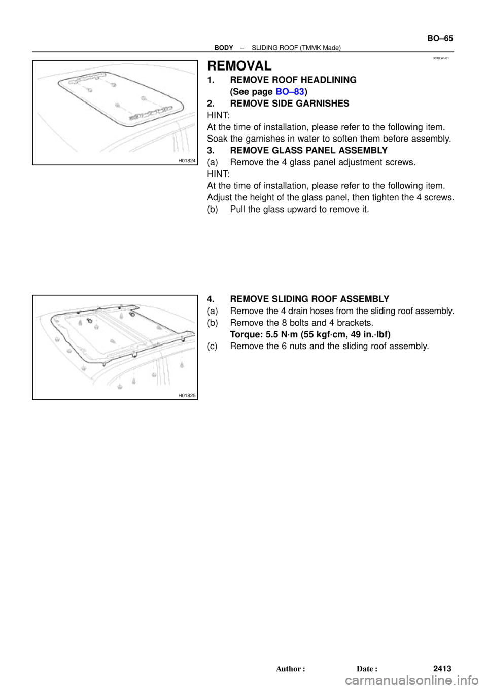
REMOVAL
1. REMOVE ROOF HEADLINING
(See page BO±83)
2. REMOVE SIDE GARNISHES
HINT:
At the time of installation, please refer to the following item.
Soak the garnishes in water to soften them before assembly.
3. REMOVE GLASS PANEL ASSEMBLY
(a) Remove the 4 glass panel adjustment screws.
HINT:
At the time of installation, please refer to the following item.
Adjust the height of the glass panel, then tighten the 4 screws.
(b) Pull the glass upward to remove it.
4. REMOVE SLIDING ROOF ASSEMBLY
(a) Remove the 4 drain hoses from the sliding roof assembly.
(b) Remove the 8 bolts and 4 brackets.
Torque: 5.5 N´m (55 kgf´cm, 49 in.´lbf)
(c) Remove the 6 nuts and the sliding roof assembly.
Page 912 of 4592

Gear Pointer (Brown)
H01818
H01819
H01820
Parts shown
disassembled
for clarity BO±68
± BODYSLIDING ROOF (TMMK Made)
2416 Author�: Date�:
ADJUSTMENT
1. A")
BO0LY±01
H01817
Motor Housing
Pointer (Grey)
Gear Pointer (Brown)
H01818
H01819
H01820
Parts shown
disassembled
for clarity BO±68
± BODYSLIDING ROOF (TMMK Made)
2416 Author�: Date�:
ADJUSTMENT
1. ALIGN THE MOTOR TO ºOº POSITION
NOTICE:
The ºOº position is the same as the sliding roof ºflush º
position (sliding roof closed).
Use the vehicle sliding roof switch or a hex wrench to align the
gear pointer with the motor housing pointer as shown.
NOTICE:
Use only the sliding roof switch to electrically operate the
motor or sliding roof. Do not use any other electrical
source to power the motor. If the sliding roof switch (under
vehicle power) is not available, use a hex wrench to align
the motor pointers.
2. REMOVE DRIVE GEAR ASSEMBLY
3. REMOVE GLASS PANEL
(a) Remove the 4 glass panels adjustment screws.
HINT:
At the time of installation, please refer to the following item.
Adjust the height of the glass panel, then tighten the 4 screws.
(b) Pull the glass upward to remove it.
4. ALIGN SLIDING ROOF COMPONENTS
(a) Verify the hook appears as shown.
(b) Align the cable arm hole with the lift arm hole.
HINT:
Using a screwdriver, move the LH and RH cable assemblies for-
ward and backward to align the holes in the cable arm and lifter
arm.
(c) Temporarily insert a 3 mm (0.12 in.) pin through the align-
ment holes in the cable arm and lifter arm.
HINT:
Verify the cam block alignment hole is aligned with the lift arm
alignment hole. Misalignment at this point will result in a mal-
function of the sliding roof mechanism.
5. REINSTALL DRIVE GEAR ASSEMBLY
HINT:
Before reinstalling the drive gear assembly, double check the
alignment of the gear pointers.
Page 1019 of 4592

R00954
Stop Light
Switch
Push Rod
Pedal HeightBR0YH±01
R00935
Pedal Freeplay
± BRAKEBRAKE PEDAL
BR±5
2028 Author�: Date�:
BRAKE PEDAL
ON±VEHICLE INSPECTION
1. CHECK PEDAL HEIGHT
Pedal height from asphalt sheet:
152.0 ± 162.0 mm (5.984 ± 6.378 in.)
2. IF NECESSARY, ADJUST PEDAL HEIGHT
(a) Disconnect the connector from the stop light switch.
(b) Loosen the stop light switch lock nut and remove the stop
light switch.
(c) Loosen the push rod lock nut.
(d) Adjust the pedal height by turning the pedal push rod.
(e) Tighten the push rod lock nut.
Torque: 25 N´m (260 kgf´cm, 19 ft´lbf)
(f) Install the stop light switch and turn it until it lightly con-
tacts the pedal stopper.
(g) Push in the brake pedal 5±15 mm (0.20±0.59 in.), turn the
stop light switch to lock the nut in the position where the
stop light goes off.
(h) Connect the connector to the stop light switch.
(i) After installation, push in the brake pedal 5±15 mm
(0.20±0.59 in.), check that stop light lights up.
(j) Connect the connector to the stop light switch.
(k) After adjusting the pedal height, check the pedal freeplay.
3. CHECK PEDAL FREEPLAY
(a) Stop the engine and depress the brake pedal several
times until there is no more vacuum left in the booster.
(b) Push in the pedal by hand until the resistance begins to
be felt, then measure the distance.
Pedal freeplay: 1 ± 6 mm (0.04 ± 0.24 in.)
HINT:
The freeplay to the 1st resistance is due to the play between the
clevis and pin. This is magnified up to 1 ± 6 mm (0.04 ± 0.24 in.)
at the pedal.
If incorrect, check the stop light switch clearance.
If the clearance is OK, then troubleshoot the brake system.
Stop light switch clearance:
0.5 ± 2.4 mm (0.020 ± 0.094 in.)
Page 1120 of 4592
 or more
Release
Point
Full Stroke
End Posit")
Q10088
Pedal Height
Adjust Point
Push Rod Play
and Freeplay
Adjust Point
Push Rod Play
Pedal Height
CL035±01
CL0042
Pedal Freeplay
CL0512
25 mm (0.98 in. ) or more
Release
Point
Full Stroke
End Position CL±2
± CLUTCHCLUTCH PEDAL
1781 Author�: Date�:
CLUTCH PEDAL
INSPECTION
1. CHECK THAT PEDAL HEIGHT IS CORRECT
Pedal height from asphalt sheet:
1MZ±FE: 161.8 ± 171.8 mm (6.370 ± 6.764 in.)
5S±FE: 156.8 ± 166.8 mm (6.173 ± 6.567 in.)
2. IF NECESSARY, ADJUST PEDAL HEIGHT
Loosen the lock nut and turn the stopper bolt until the height is
correct. Tighten the lock nut.
3. CHECK THAT PEDAL FREEPLAY AND PUSH ROD
PLAY ARE CORRECT
Push in on the pedal until the beginning of clutch resistance is
felt.
Pedal freeplay: 5.0 ± 15.0 mm (0.197 ± 0.591 in.)
Gently push the pedal until the resistance begins to increase a
little.
Push rod play at pedal top:
1.0 ± 5.0 mm (0.039 ± 0.197 in.)
4. IF NECESSARY, ADJUST PEDAL FREEPLAY AND
PUSH ROD PLAY
(a) Loosen the lock nut and turn the push rod until the free-
play and push rod play are correct.
(b) Tighten the lock nut.
(c) After adjusting the pedal freeplay, check the pedal height.
(d) Connect the air duct and install the lower finish panel.
5. INSPECT CLUTCH RELEASE POINT
(a) Pull the parking brake lever and install wheel stopper.
(b) Start the engine and idle the engine.
(c) Without depressing the clutch pedal, slowly shift the shift
lever into reverse position until the gears contact.
(d) Gradually depress the clutch pedal and measure the
stroke distance from the point the gear noise stops (re-
lease point) up to the full stroke end position.
Standard distance:
25 mm (0.98 in.) or more
(From pedal stroke end position to release point)
If the distance not as specified, do the following operation.
�Inspect pedal height.
�Inspect push rod play and pedal freeplay.
�Bleed the clutch line.
�Inspect the clutch cover and disc.
Page 1162 of 4592
RADIATOR
1596 Author�: Date�:
(b) Check the lock plate height (H) after completing the caulk-
ing.
Plate height: 7.40 ± 7.8")
S04700
H
S04704
SST
S01713
Tank
Lock
O±RingPlate CO±22
± COOLING (5S±FE)RADIATOR
1596 Author�: Date�:
(b) Check the lock plate height (H) after completing the caulk-
ing.
Plate height: 7.40 ± 7.80 mm (0.2913 ± 0.3071 in.)
If not within the specified height, adjust the stopper bolt of the
handle again and caulk again.
6. INSTALL ECT SWITCH
(a) Install a new O±ring to the ECT switch.
(b) Install the ECT switch.
7. INSTALL DRAIN PLUG
(a) Install a new O±ring to the drain plug.
(b) Install the drain plug.
8. INSPECT FOR WATER LEAKS
(a) Plug the inlet and outlet pipes of the radiator with SST.
SST 09230±01010
(b) Using a radiator cap tester, apply pressure to the radiator.
Test pressure: 177 kPa (1.8 kgf/cm
2, 26 psi)
(c) Submerge the radiator in water.
(d) Inspect for leaks.
HINT:
On radiators with resin tanks, there is a clearance between the
tank and lock plate where a minute amount of air will remain,
giving the appearance of an air leak when the radiator is sub-
merged in water. Therefore, before doing the water leak test,
first swish the radiator around in the water until all air bubbles
disappear.
![TOYOTA CAMRY 1999 Service Repair Manual AUTOMATIC TRANSAXLEUPPER VALVE BODY ±
AX±89
RETAINERS, PIN, AND CHECK BALLS LOCATION
1. PIN, RETAINERS
MarkNameHeight / Width / Thickness
mm (in.)
@@@@@: [c A]B1 Orifice Control Valve8.9 (0.350) / 5](/manual-img/14/57448/w960_57448-537.png "TOYOTA CAMRY 1999 Service Repair Manual AUTOMATIC TRANSAXLEUPPER VALVE BODY ±
AX±89
RETAINERS, PIN, AND CHECK BALLS LOCATION
1. PIN, RETAINERS
MarkNameHeight / Width / Thickness
mm (in.)
@@@@@: [c A]B1 Orifice Control Valve8.9 (0.350) / 5")
![TOYOTA CAMRY 1999 Service Repair Manual AUTOMATIC TRANSAXLELOWER VALVE BODY ±
AX±93
RETAINERS AND CHECK BALLS LOCATION
1. RETAINERS
MarkNameHeight / Width / Thickness mm (in.)
@@@@@: [c A]Accumulator Control Valve8.5 (0.335) / 5.0 (0.197](/manual-img/14/57448/w960_57448-541.png "TOYOTA CAMRY 1999 Service Repair Manual AUTOMATIC TRANSAXLELOWER VALVE BODY ±
AX±93
RETAINERS AND CHECK BALLS LOCATION
1. RETAINERS
MarkNameHeight / Width / Thickness mm (in.)
@@@@@: [c A]Accumulator Control Valve8.5 (0.335) / 5.0 (0.197")