Page 31 of 4592
 Install the p")
AC0LX±02
N21046
N21045
Packing Paper
N21044
± AIR CONDITIONINGAIR CONDITIONING UNIT
AC±31
2513 Author�: Date�:
REASSEMBLY
1. INSTALL THERMISTOR TO EVAPORATOR
2. INSTALL EVAPORATOR
(a) Install the plate to the evaporator.
(b) Install the evaporator on the insulator.
(c) Connect the heater case with the 13 screws.
NOTICE:
The packing for water seal should be replaced, with a new
one when the A/C unit is reassembled.
(d) Install the 2 new packings.
(e) Install the grommet to evaporator.
HINT:
If evaporator is replaced, add compressor oil to the compressor.
Add 40 ± 50 cc (1.4 ± 1.7 fl.oz.)
Compressor oil: ND ± OIL 8 or equivalent
3. INSTALL EXPANSION VALVE
(a) Lubricate 2 new O±rings with compressor oil and install
the tubes.
(b) Install the liquid tube and suction tube on the expansion
valve.
(c) Using a knife, cut off packing paper of packing while peel
off the paper, as shown in the illustration.
HINT:
Leave the packing paper untaped on the tube side so that the
installation bolt hole for remains visible.
(d) Apply new packing.
NOTICE:
Do not overtape the packing beyond the expansion valve
edge.
Page 32 of 4592
N20283
N20245
Pin
Pin AC±32
± AIR CONDITIONINGAIR CONDITIONING UNIT
2514 Author�: Date�:
(e) Lubricate 2 new O±rings with compressor oil and install
the expansion valve.
(f) Install the expansion valve with the tubes to evaporator
with the 2 bolts.
Torque: 5.4 N´m (55 kgf´cm, 48 in.´lbf)
NOTICE:
When installing the expansion valve, take care so that the
packing is not jammed with the evaporator.
(g) Peel off the remaining packing paper and apply the pack-
ing to expansion valve.
4. INSTALL HEATER RADIATOR
(a) Install the heater radiator to heater case.
(b) Install the heater radiator pipe with 2 clips.
(c) Install the 3 clamps with the 3 screws.
5. INSTALL MODE SERVOMOTOR
(a) Install the servomotor with the 3 screws.
(b) Insert the drain of the plate to the pin and install plate.
Page 60 of 4592
AC0MM±02
± AIR CONDITIONINGEXPANSION VALVE
AC±59
2541 Author�: Date�:
EXPANSION VALVE
ON±VEHICLE INSPECTION
1. CHECK QUANTITY OF GAS DURING REFRIGERATION CYCLE
2. SET ON MANIFOLD GAUGE SET (See page AC±19)
3. RUN ENGINE
Run the engine at 1,500 rpm for at least 5 minutes.
Then check that the high pressure reading is 1.37 ± 1.57 MPa (14 ± 16 kgf/cm
2, 199 ± 228 psi).
4. CHECK EXPANSION VALVE
If the expansion valve is faulty, the low pressure reading will drop to 0 kPa (0 kgf/cm
2, 0 psi).
HINT:
When the low pressure drops to 0 kPa (0 kgf/cm
2, 0 psi), check the receiver's IN and OUT sides is no temper-
ature difference.
Page 61 of 4592
AC220±01
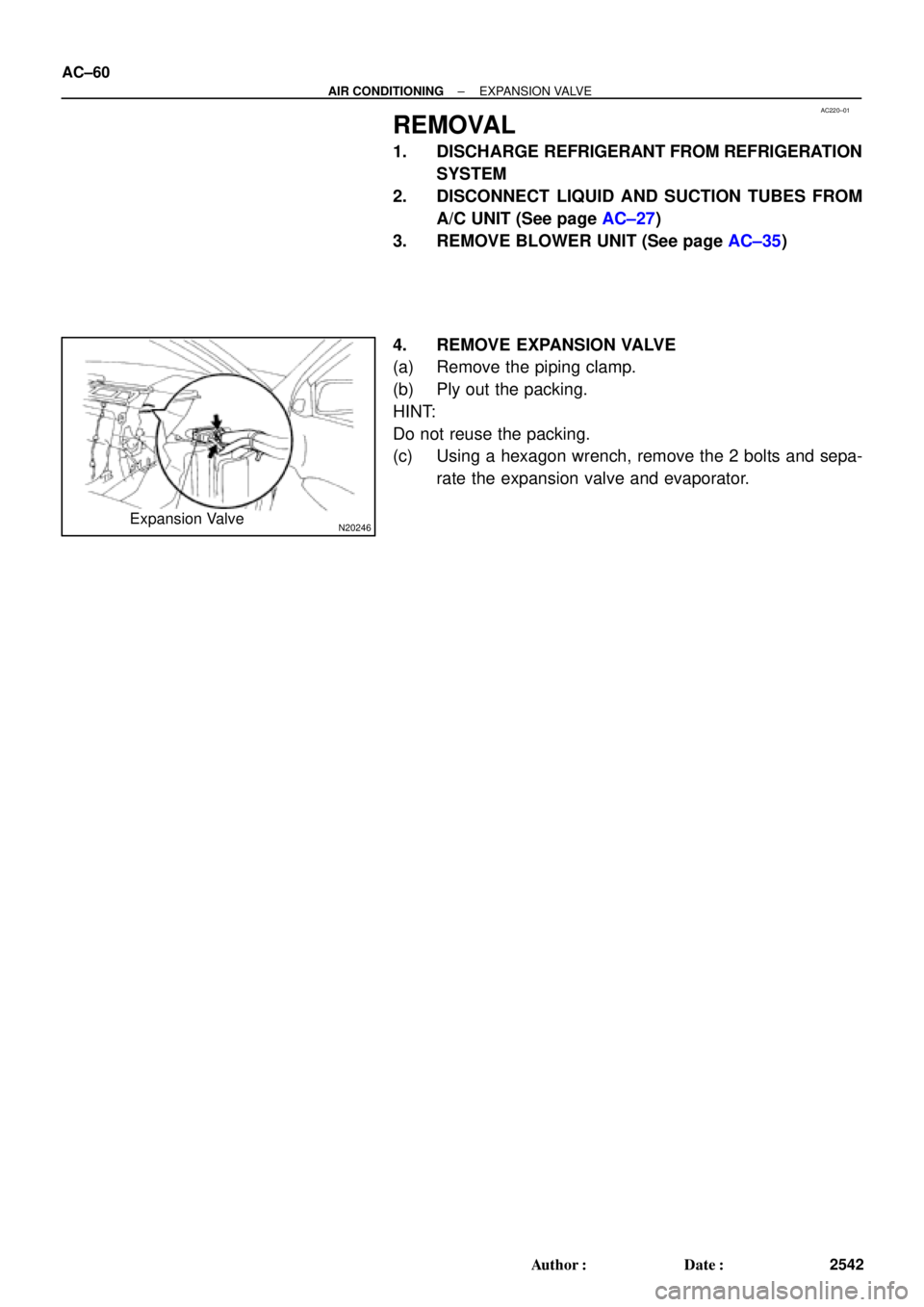
N20246Expansion Valve AC±60
± AIR CONDITIONINGEXPANSION VALVE
2542 Author�: Date�:
REMOVAL
1. DISCHARGE REFRIGERANT FROM REFRIGERATION
SYSTEM
2. DISCONNECT LIQUID AND SUCTION TUBES FROM
A/C UNIT (See page AC±27)
3. REMOVE BLOWER UNIT (See page AC±35)
4. REMOVE EXPANSION VALVE
(a) Remove the piping clamp.
(b) Ply out the packing.
HINT:
Do not reuse the packing.
(c) Using a hexagon wrench, remove the 2 bolts and sepa-
rate the expansion valve and evaporator.
Page 62 of 4592
AC0MO±02
N21046
N21045
N21044
± AIR CONDITIONINGEXPANSION VALVE
AC±61
2543 Author�: Date�:
INSTALLATION
1. INSTALL LIQUID TUBE AND SUCTION TUBE TO EX-
PANSION VALVE
HINT:
Lubricate 4 new O±rings with compressor oil and install the
tubes.
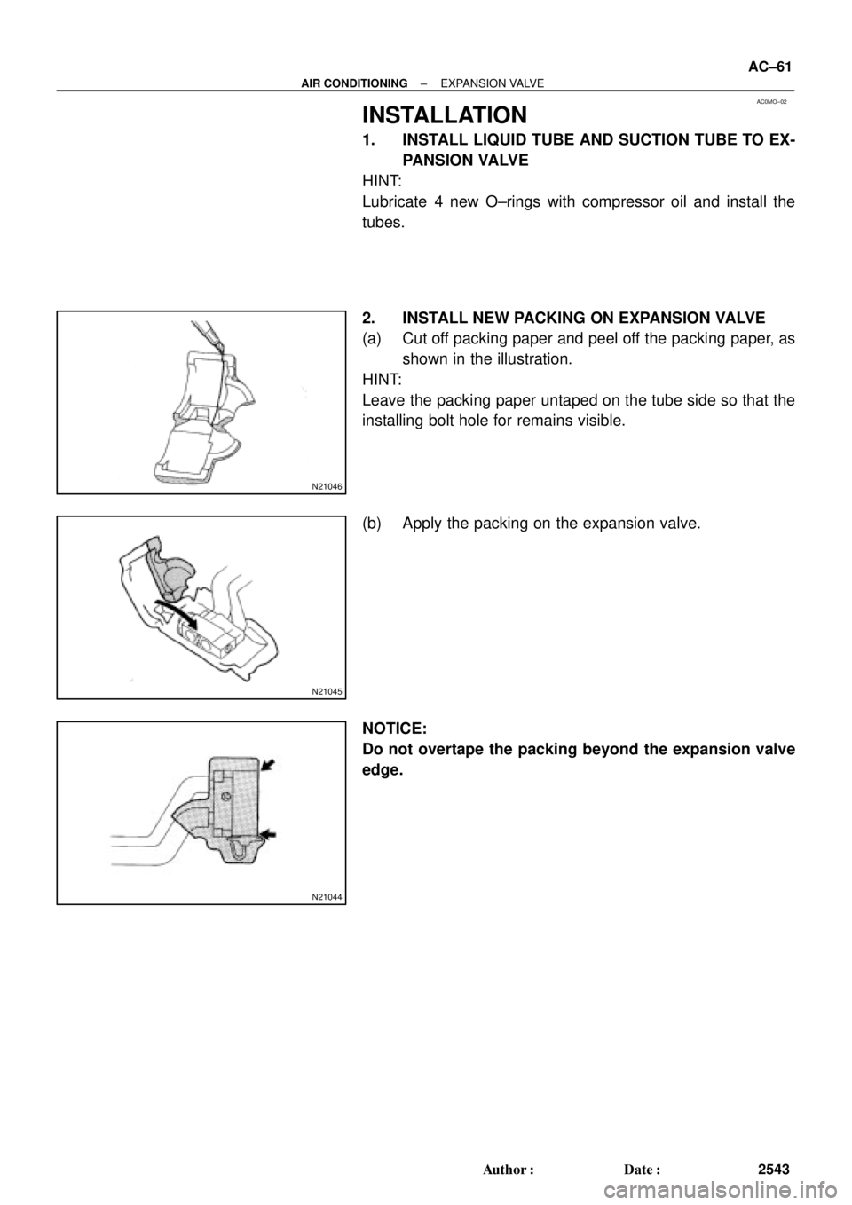
2. INSTALL NEW PACKING ON EXPANSION VALVE
(a) Cut off packing paper and peel off the packing paper, as
shown in the illustration.
HINT:
Leave the packing paper untaped on the tube side so that the
installing bolt hole for remains visible.
(b) Apply the packing on the expansion valve.
NOTICE:
Do not overtape the packing beyond the expansion valve
edge.
Page 63 of 4592
N20246
AC±62
± AIR CONDITIONINGEXPANSION VALVE
2544 Author�: Date�:
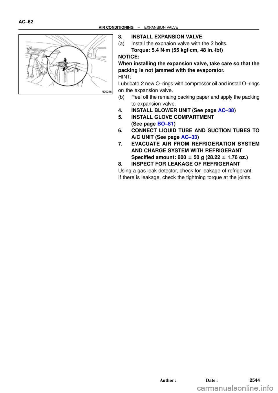
3. INSTALL EXPANSION VALVE
(a) Install the expnaion valve with the 2 bolts.
Torque: 5.4 N´m (55 kgf´cm, 48 in.´lbf)
NOTICE:
When installing the expansion valve, take care so that the
packing is not jammed with the evaporator.
HINT:
Lubricate 2 new O±rings with compressor oil and install O±rings
on the expansion valve.
(b) Peel off the remaing packing paper and apply the packing
to expansion valve.
4. INSTALL BLOWER UNIT (See page AC±38)
5. INSTALL GLOVE COMPARTMENT
(See page BO±81)
6. CONNECT LIQUID TUBE AND SUCTION TUBES TO
A/C UNIT (See page AC±33)
7. EVACUATE AIR FROM REFRIGERATION SYSTEM
AND CHARGE SYSTEM WITH REFRIGERANT
Specified amount: 800 ± 50 g (28.22 ± 1.76 oz.)
8. INSPECT FOR LEAKAGE OF REFRIGERANT
Using a gas leak detector, check for leakage of refrigerant.
If there is leakage, check the tightning torque at the joints.
Page 2237 of 4592

DI±86
± DIAGNOSTICSENGINE
DTC P1190 Fuel Pressure Regulator Malfunction
CIRCUIT DESCRIPTION
The fuel pressure regulator regulates the fuel pressure by reducing the pressure of the compressed fuel from
the fuel tank to the fuel injection pressure, which is 785 kPa (8 kgf/cm
2, 114 psi).
Similar to the fuel shutoff valve for the fuel tank, a fuel shutoff valve is provided on the fuel inlet side of the
fuel pressure regulator to shutoff the supply of fuel when the engine is stopped or during abnormal condi-
tions.
A reservoir that traps the moisture and oil in the fuel is provided on the low pressure side.
A built±in relief valve is provided to protect the parts located on the low pressure side.
While the fuel pressure is being reduced by the fuel pressure regulator, the Joule±Thompson effect
associated with the expansion of the fuel causes the fuel pressure regulator to be cooled excessively, exert-
ing unfavorable influence on the rubber parts such as diaphragms and fuel hoses.
Therefore, to raise the fuel temperature, a water passage is provided in the fuel pressure regulator to allow
the engine coolant to warm the regulator.
DTC No.DTC Detecting ConditionTrouble Area
P1190After engine is warmed up, detection of pressure control
malfunction (2 trip detection logic)
�Open or short in fuel shutoff valve circuit for fuel tank
�Fuel shutoff valve for fuel tank
�Open or short in fuel shutoff valve circuit for fuel pressure
regulator
�Fuel shutoff valve for fuel pressure regulator
�Fuel fuel pressure regulator
�Open or short in fuel shutoff valve circuit for fuel delivery
pipe
�Fuel shutoff valve for fuel delivery pipe
�ECM
DI64X±01
Page 3310 of 4592
SS05W±06
SS±72
± SERVICE SPECIFICATIONSAIR CONDITIONING
235 Author�: Date�:
TORQUE SPECIFICATION
Part tightenedN´mkgf´cmft´lbf
Compressor x Discharge hose101007
Compressor x Suction hose101007
Condenser x Disaharge hose101007
Condenser x Liquid tube1414010
Receiver x Liquid tube5.45548 in.´lbf
Expansion valve x Evaporator5.45548in.´lbf
Compressor x Engine2525018
Compressor x Compressor bracket (1MZ±FE Only)2525018
Drive belt adjusting bar bracket x Compressor2525018
Drive belt adjusting bar bracket x Adjusting bar1818513
Pivot bolt 5S±FE5252038Pivot bolt 5S FE
1MZ±FE5657041
Adjusting lock bolt1818513
Pressure switch x Liquied tube101007
Pressure plate x Compressor13.21359
Suction line (Piping joint)3233024
Suction line (Block joint)101007