Page 123 of 4592
AX03M±01
D01018
O/D Direct Clutch (C0)2nd Brake (B2)
Forward Clutch
(C
1) O/D Brake (B
0)2nd Coast Brake
(B
1)
Intermediate Shaft1st and Reverse
Brake (B3)
One±Way Clutch
No.2 (F
2) Planetary Gear Unit
O/D Planetary GearCounter Drive
Gear
Front Planetary Gear Rear Planetary GearOne±Way Clutch
No.1 (F
1)
Input ShaftDirect Clutch
(C
2)
O/D One±Way Clutch
(F
0)
P
R
N
L2 Shift Lever
Position
DGear Position
Parking
Reverse
Neutral
1st
2nd
3rd
O/D
1st
2nd
*3rd
1st
*2ndC
0C1C2B0F0F1F2B1B3B2
*Down±shift only ± no up±shift
: Operating
AX±2
± AUTOMATIC TRANSAXLE (A541E)AUTOMATIC TRANSAXLE SYSTEM
1922 Author�: Date�:
OPERATION
Page 126 of 4592
AX03P±01
Q00229
Q06496
Q05727
Q04617
± AUTOMATIC TRANSAXLE (A541E)PARK/NEUTRAL POSITION (PNP) SWITCH
AX±5
1925 Author�: Date�:
PARK/NEUTRAL POSITION (PNP)
SWITCH
ON±VEHICLE REPAIR
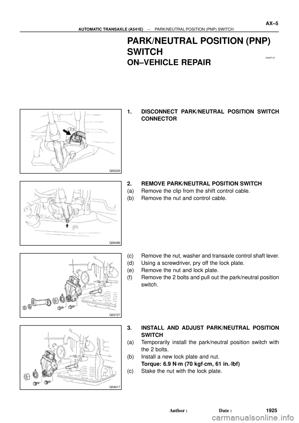
1. DISCONNECT PARK/NEUTRAL POSITION SWITCH
CONNECTOR
2. REMOVE PARK/NEUTRAL POSITION SWITCH
(a) Remove the clip from the shift control cable.
(b) Remove the nut and control cable.
(c) Remove the nut, washer and transaxle control shaft lever.
(d) Using a screwdriver, pry off the lock plate.
(e) Remove the nut and lock plate.
(f) Remove the 2 bolts and pull out the park/neutral position
switch.
3. INSTALL AND ADJUST PARK/NEUTRAL POSITION
SWITCH
(a) Temporarily install the park/neutral position switch with
the 2 bolts.
(b) Install a new lock plate and nut.
Torque: 6.9 N´m (70 kgf´cm, 61 in.´lbf)
(c) Stake the nut with the lock plate.
Page 127 of 4592
Z10304
Neutral
Basic
Line
Groove
Q04687
Q06496
AX±6
± AUTOMATIC TRANSAXLE (A541E)PARK/NEUTRAL POSITION (PNP) SWITCH
1926 Author�: Date�:
(d) Adjust the park/neutral position switch.
(See page DI±438)
(e) Install the transaxle control shaft lever and washer.
(f) Install and torque the nut.
Torque: 15 N´m (150 kgf´cm, 11 ft´lbf)
(g) Install the control cable and nut.
Torque: 15 N´m (150 kgf´cm, 11 ft´lbf)
(h) Install the clip to the shift control cable.
4. CONNECT PARK/NEUTRAL POSITION SWITCH CON-
NECTOR
5. TEST DRIVE VEHICLE
Page 138 of 4592
 5 (IG)
4 (KLS+)
3 (E)
2 (STP)
Wire Harness Side
Q09456
1 (KLS+)
2 (E)
Q09457
1 (KLS+)
2 (E)
(±) (+)
± AUTOMATIC TRANSAXLE (A541E)SHIFT LOCK SYSTEM (TMC Made)
AX±17
1937 Aut")
AX03U±02
Q09455
1 (ACC) 5 (IG)
4 (KLS+)
3 (E)
2 (STP)
Wire Harness Side
Q09456
1 (KLS+)
2 (E)
Q09457
1 (KLS+)
2 (E)
(±) (+)
± AUTOMATIC TRANSAXLE (A541E)SHIFT LOCK SYSTEM (TMC Made)
AX±17
1937 Author�: Date�:
INSPECTION
1. INSPECT SHIFT LOCK CONTROL UNIT ASSEMBLY
Using a voltmeter, measure the voltage at each terminal.
HINT:
Do not disconnect the shift lock control unit assembly connec-
tor.
TerminalMeasuring ConditionVoltage (V)
1 ± 3 (ACC ± E)Ignition switch ACC10 ± 14
5 ± 3 (IG ± E)Ignition switch ON10 ± 14
2 ± 3 (STP ± E)Depressing brake pedal10 ± 14
4 ± 3 (KLS+ ± E)
(1) Ignition switch ACC and P position
(2) Ignition switch ACC and except P position
(3) Ignition switch ACC and except P position (After approx. 1 second)0
7.5 ± 11
6 ± 9.5
2. INSPECT KEY INTERLOCK SOLENOID
(a) Disconnect the solenoid connector.
(b) Using an ohmmeter, measure resistance between termi-
nals.
Standard resistance: 12.5 ± 16.5 W
If resistance value is not as specified, replace the solenoid.
(c) Apply battery positive voltage between terminals. Check
that an operation noise can be heard from the solenoid.
If the solenoid does not operated, replace the solenoid.
Page 140 of 4592

1 (P)
4 (KLS+) 3 (IG)
6 (STP)
5 (E)
BBack Side
Front Side A
4 (P2)
5 (SLS±)
3 (P1)
2 (SLS+)
Q09460
5 (SLS±)
2 (SLS+)
Q09461
5 (SLS±)
2 (SLS+)
± AUTOMATIC TRANSAXLE (A541E)")
AX03W±01
Q09459
1 (ACC)
1 (P)
4 (KLS+) 3 (IG)
6 (STP)
5 (E)
BBack Side
Front Side A
4 (P2)
5 (SLS±)
3 (P1)
2 (SLS+)
Q09460
5 (SLS±)
2 (SLS+)
Q09461
5 (SLS±)
2 (SLS+)
± AUTOMATIC TRANSAXLE (A541E)SHIFT LOCK SYSTEM (TMMK Made)
AX±19
1939 Author�: Date�:
INSPECTION
1. INSPECT SHIFT LOCK CONTROL ECU
Using a voltmeter, measure voltage at each terminal.
HINT:
Do not disconnect the ECU connector.
TerminalMeasuring ConditionVoltage (V)
A, 1 ± A, 5 (ACC ± E)Ignition switch ACC10 ± 14
A, 3 ± A, 5 (IG ± E)Ignition switch ON10 ± 14
A, 6 ± A, 5 (STP ± E)Depressing brake pedal10 ± 14
A, 4 ± A, 5 (KLS+ ± E)
(1) Ignition switch ACC and P position
(2) Ignition switch ACC and except P position
(3) Ignition switch ACC and except P position (After approx. 1 second)0
7.5 ± 11
6 ± 9.5
B, 2 ± B, 5 (SLS+ ± SLS±)
(1) Ignition switch ON and P position
(2) Depress brake pedal
(3) Except P position0
8 ± 13.5
0
B, 3 ± B, 1 (P1 ± P)(1) Ignition switch ON, P position and depress brake pedal
(2) Shift except P position under conditions above0
9 ± 13.5
B, 4 ± B, 1 (P2 ± P)(1) Ignition switch ACC, P position
(2) Shift except P position under conditions above9 ± 13.5
0
2. INSPECT SHIFT LOCK SOLENOID
(a) Disconnect the solenoid connector.
(b) Using an ohmmeter, measure resistance between termi-
nals.
Standard resistance: 29 ± 35 W
If resistance value is not as specified, replace the solenoid.
(c) Apply battery positive voltage between terminals. Check
that operation.
If the solenoid does not operated, replace the solenoid noise
can be heard from the solenoid.
Page 141 of 4592
Q09456
1 (KLS+)
2 (E)
Q09457
1 (KLS+)
2 (E)
(±) (+)
Q09464
3 (P1) 4 (P2) 1 (P) AX±20
± AUTOMATIC TRANSAXLE (A541E)SHIFT LOCK SYSTEM (TMMK Made)
1940 Author�: Date�:
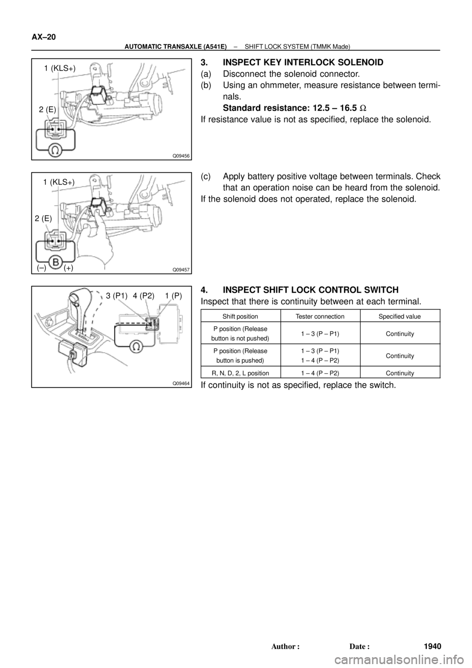
3. INSPECT KEY INTERLOCK SOLENOID
(a) Disconnect the solenoid connector.
(b) Using an ohmmeter, measure resistance between termi-
nals.
Standard resistance: 12.5 ± 16.5 W
If resistance value is not as specified, replace the solenoid.
(c) Apply battery positive voltage between terminals. Check
that an operation noise can be heard from the solenoid.
If the solenoid does not operated, replace the solenoid.
4. INSPECT SHIFT LOCK CONTROL SWITCH
Inspect that there is continuity between at each terminal.
Shift positionTester connectionSpecified value
P position (Release
button is not pushed)1 ± 3 (P ± P1)Continuity
P position (Release
button is pushed)1 ± 3 (P ± P1)
1 ± 4 (P ± P2)Continuity
R, N, D, 2, L position1 ± 4 (P ± P2)Continuity
If continuity is not as specified, replace the switch.
Page 144 of 4592
AUTOMATIC TRANSAXLE UNIT
AX±23
1943 Author�: Date�:
REMOVAL
1. REMOVE BATTERY
2. REMOVE AIR CLEANER ASSEMBLY
3. REMOVE THROT")
AX03Y±01
Q00225
Q09982
Q10287
Q00075
Q10028
± AUTOMATIC TRANSAXLE (A541E)AUTOMATIC TRANSAXLE UNIT
AX±23
1943 Author�: Date�:
REMOVAL
1. REMOVE BATTERY
2. REMOVE AIR CLEANER ASSEMBLY
3. REMOVE THROTTLE CABLE FROM THROTTLE
BODY
Torque: 15 N´m (150 kgf´cm, 11 ft´lbf)
4. w/ Cruise Control:
REMOVE CRUISE CONTROL ACTUATOR
(a) Disconnect the connector.
(b) Remove the 3 bolts and disconnect cruise control actua-
tor with the bracket.
Torque: 13 N´m (130 kgf´cm, 9 ft´lbf)
5. DISCONNECT GROUND CABLE
6. DISCONNECT VEHICLE SPEED SENSOR CONNEC-
TOR
7. DISCONNECT DIRECT CLUTCH SPEED SENSOR
CONNECTOR
8. DISCONNECT PARK/NEUTRAL POSITION SWITCH
CONNECTOR
9. DISCONNECT SOLENOID CONNECTOR
10. DISCONNECT SHIFT CONTROL CABLE
(a) Remove the nut and disconnect the shift control cable
from the park/neutral position switch.
Torque: 15 N´m (150 kgf´cm, 11 ft´lbf)
(b) Remove the clip and disconnect the shift control cable.
11. REMOVE 2 ENGINE MOUNTING ABSORBER BOLTS
Torque: 48 N´m (490 kgf´cm, 35 ft´lbf)
Page 175 of 4592
AUTOMATIC TRANSAXLEOPERATION ±
AX±5
Power from the engine transmitted to the input shaft via the torque converter is then transmitted to the
planetary gears by the operation of the clutch.
By operation of the brake and one±way clutch, either the planetary carrier or the planetary sun gear
are immobilized, altering the speed of revolution of the planetary gear unit.
Shift change is carried out by altering the combination of clutch and brake operation.
Each clutch and brake operates by hydraulic pressure; gear position is decided according to the throttle
opening angle and vehicle speed, and shift change automatically occurs.
The conditions of operation for each gear position are shown on the following illustrations:
2nd Brake (B2)
Forward Clutch
(C
1) O/D Brake (B
0)2nd Coast Brake
(B
1)
Intermediate Shaft1st and Reverse
Brake (B3)
One±Way Clutch
No.2 (F
2) Planetary Gear U")