Page 3716 of 4592
DOOR GLASS DISPLACEMENT ± BO017±99 November 26, 1999
Page 2 of 2
1. Lower the door glass, disconnect the power window switch, remove the front door
trim panel, speaker, and loosen the door mirror mounts to gain access to the door
glass and lower frames. Remove the front lower frame (2 screws).
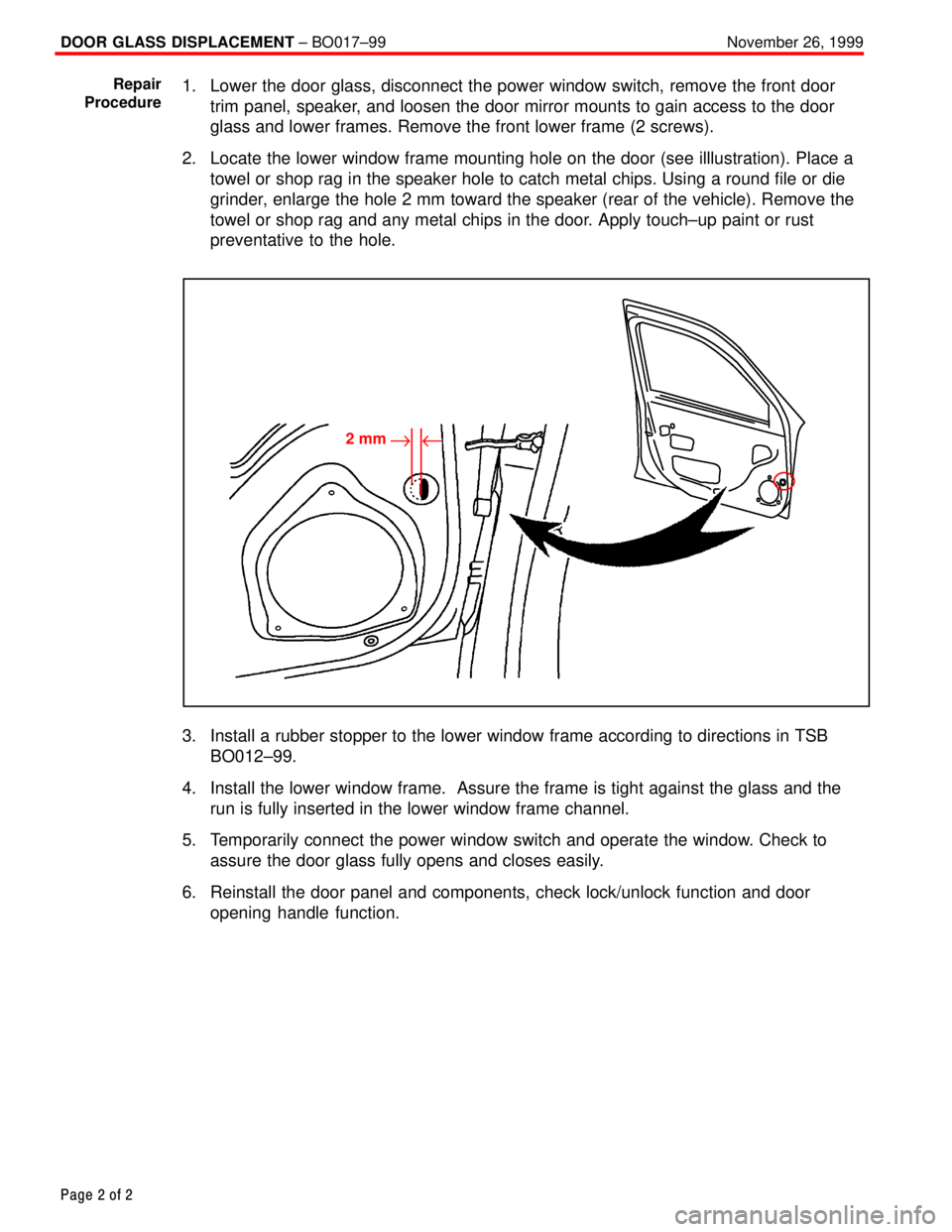
2. Locate the lower window frame mounting hole on the door (see illlustration). Place a
towel or shop rag in the speaker hole to catch metal chips. Using a round file or die
grinder, enlarge the hole 2 mm toward the speaker (rear of the vehicle). Remove the
towel or shop rag and any metal chips in the door. Apply touch±up paint or rust
preventative to the hole.
2 mm"u
3. Install a rubber stopper to the lower window frame according to directions in TSB
BO012±99.
4. Install the lower window frame. Assure the frame is tight against the glass and the
run is fully inserted in the lower window frame channel.
5. Temporarily connect the power window switch and operate the window. Check to
assure the door glass fully opens and closes easily.
6. Reinstall the door panel and components, check lock/unlock function and door
opening handle function.
Repair
Procedure
Page 3831 of 4592
Toyota Supports ASE CertificationPage 1 of 2
EL008±98Title:
PROGRAMMING OEM WIRELESS
DOOR LOCK REMOTE TRANSMITTERS
Models:
'97 ± '99 Camry
Technical Service
BULLETIN
December 4, 1998
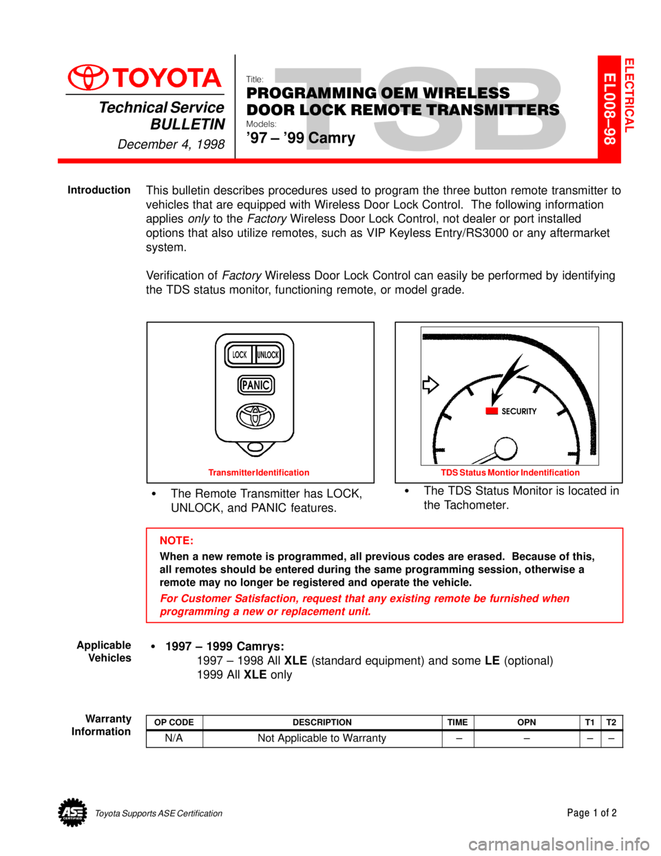
This bulletin describes procedures used to program the three button remote transmitter to
vehicles that are equipped with Wireless Door Lock Control. The following information
applies
only to the Factory Wireless Door Lock Control, not dealer or port installed
options that also utilize remotes, such as VIP Keyless Entry/RS3000 or any aftermarket
system.
Verification of
Factory Wireless Door Lock Control can easily be performed by identifying
the TDS status monitor, functioning remote, or model grade.
�The Remote Transmitter has LOCK,
UNLOCK, and PANIC features.�The TDS Status Monitor is located in
the Tachometer.
Transmitter Identification TDS Status Montior Indentification
NOTE:
When a new remote is programmed, all previous codes are erased. Because of this,
all remotes should be entered during the same programming session, otherwise a
remote may no longer be registered and operate the vehicle.
For Customer Satisfaction, request that any existing remote be furnished when
programming a new or replacement unit.
�1997 ± 1999 Camrys:
1997 ± 1998 All XLE (standard equipment) and some LE (optional)
1999 All XLE only
OP CODEDESCRIPTIONTIMEOPNT1T2
N/ANot Applicable to Warranty ±±±±
ELECTRICAL
Introduction
Applicable
Vehicles
Warranty
Information
Page 3832 of 4592
PROGRAMMING OEM WIRELESS DOOR LOCK REMOTE TRANSMITTERS ± EL008±98 December 4, 1998
Page 2 of 2
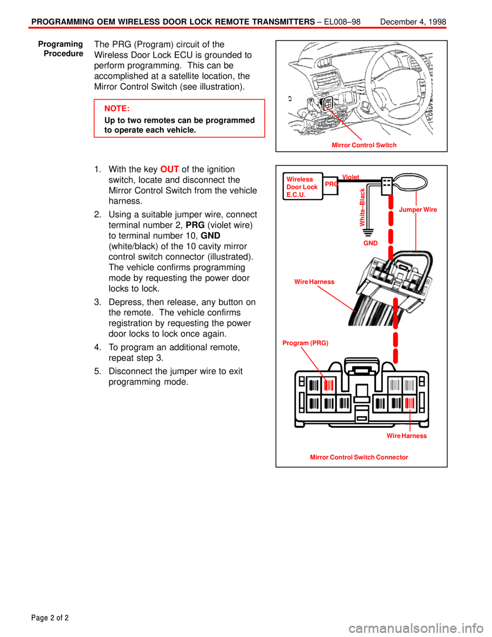
The PRG (Program) circuit of the
Wireless Door Lock ECU is grounded to
perform programming. This can be
accomplished at a satellite location, the
Mirror Control Switch (see illustration).
NOTE:
Up to two remotes can be programmed
to operate each vehicle.
1. With the key OUT of the ignition
switch, locate and disconnect the
Mirror Control Switch from the vehicle
harness.
2. Using a suitable jumper wire, connect
terminal number 2, PRG (violet wire)
to terminal number 10, GND
(white/black) of the 10 cavity mirror
control switch connector (illustrated).
The vehicle confirms programming
mode by requesting the power door
locks to lock.
3. Depress, then release, any button on
the remote. The vehicle confirms
registration by requesting the power
door locks to lock once again.
4. To program an additional remote,
repeat step 3.
5. Disconnect the jumper wire to exit
programming mode.
Mirror Control Switch
Programing
Procedure
Mirror Control Switch Connector Program (PRG)Wire HarnessJumper Wire Wireless
Door Lock
E.C.U.PRGViolet
GND
White±Black
Wire Harness
Page 3885 of 4592
WARRANTY PARTS MARKING PROCEDURE ± PG006-03September 26, 2003
Page 3 of 3
NOTE:
The following parts do not have to be marked unless the technician can determine
failure and location.
air induction/ejection systems fuel injection systems
all computers fuel injectors
alternators fuel pump
audio (internal) ignition system
batteries internal engine components
bearings internal transmission components
belts oil cooler
catalytic converter power door lock switches
crankshaft remanufactured parts
cruise control starters
distributors suspension components
EGR systems valve covers
engine control systems window regulators
exchange parts wiper motors
exhaust systems
Parts
Marking
List
(Continued)
Page 4017 of 4592
B HOW TO USE THIS MANUAL
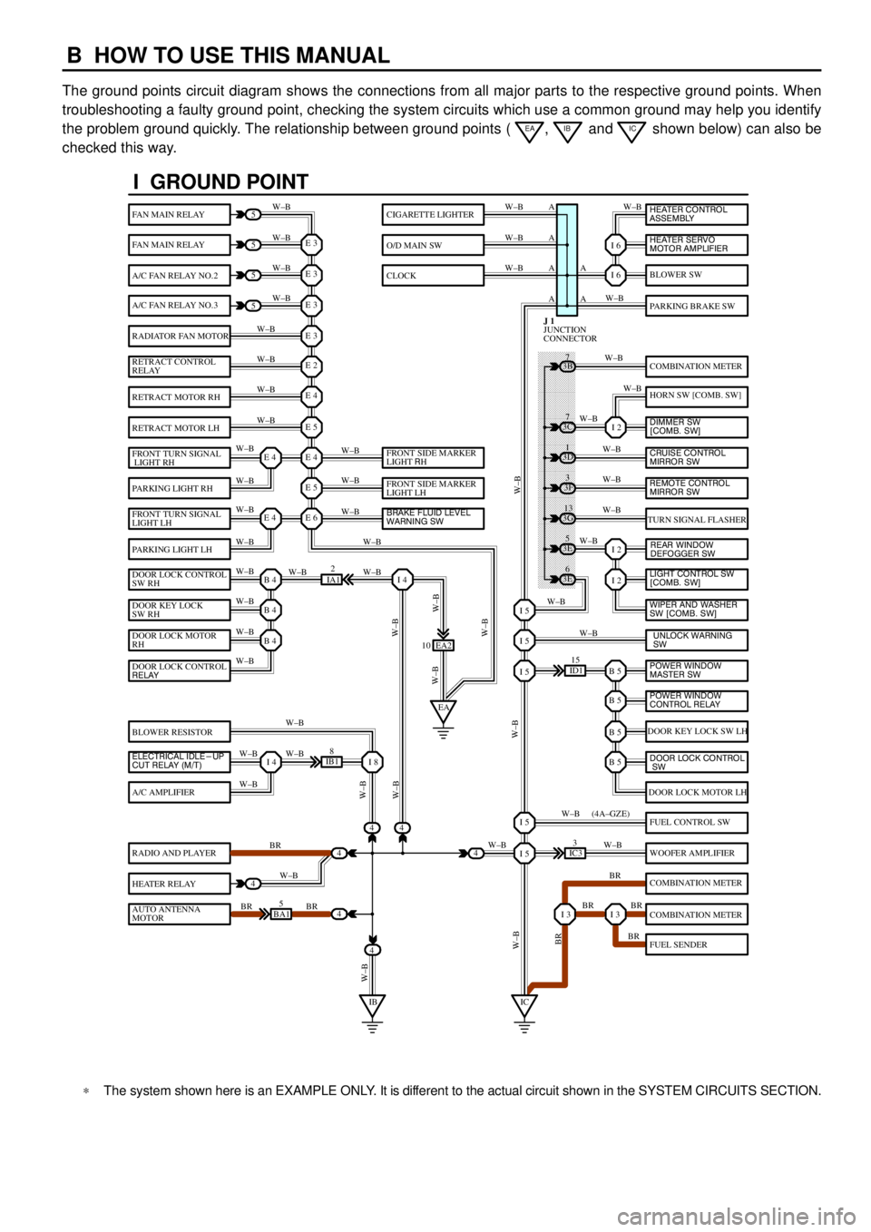
The ground points circuit diagram shows the connections from all major parts to the respective ground points. When
troubleshooting a faulty ground point, checking the system circuits which use a common ground may help you identify
the problem ground quickly. The relationship between ground points (
EA, IB and IC shown below) can also be
checked this way.
���� ���� ���� ���� ���� ���� ���� ���� ���� ���� ���� ���� ���� ���� ���� ���� ���� ���� ����
I GROUND POINT
FAN MAIN RELAY
FAN MAIN RELAY
A/C FAN RELAY NO.2
A/C FAN RELAY NO.3
RADIATOR FAN MOTOR
RETRACT CONTROL
RELAY
RETRACT MOTOR RH
RETRACT MOTOR LH
FRONT TURN SIGNAL
LIGHT RH
PARKING LIGHT RH
FRONT TURN SIGNAL
LIGHT LH
PARKING LIGHT LH
DOOR LOCK CONTROL
SW RH
DOOR KEY LOCK
SW RH
DOOR LOCK MOTOR
RH
BLOWER RESISTOR
A/C AMPLIFIER
RADIO AND PLAYER
HEATER RELAY
AUTO ANTENNA
MOTOR
BLOWER SW
PARKING BRAKE SW
COMBINATION METER
HORN SW [COMB. SW]
TURN SIGNAL FLASHER
DOOR KEY LOCK SW LH
DOOR LOCK MOTOR LH
FUEL CONTROL SW
WOOFER AMPLIFIER
COMBINATION METER
COMBINATION METER
FUEL SENDER
CIGARETTE LIGHTER
O/D MAIN SW
CLOCK
5
5
5
5
4
4
4
4
4BA15
IB18
EA2 10
3E5
3E
6 3G
13 3F
3 3D
1 3B
7
ID115
IC33
IA12
E 3
A
A AW±B
W±BW±B W±B
W±B W±B
W±B
W±B
W±B
W±B
W±B
W±B
W±B
W±B
W±B W±BW±B W±B W±B W±B
W±B W±B
W±BW±B
W±B
W±B
W±B W±B
W±B
BR
W±B
BR BRW±BW±B
W±B
W±B
W±B
W±B
W±B
W±B
W±B
W±B
W±B W±B
W±B
W±B
W±B
W±B
BR W±B
BR BR
BR W±B W±BW±B
W±BW±BBR W±B (4A±GZE)
W±B A A A
I 6
I 6
I 2
I 2
I 2
B 5I 5
I 5
I 5
B 5
B 5
B 5
I 5
I 5
I 3I 3
E 3
E 3
E 3
E 2
E 4
E 5
E 4
E 5
E 6E 4
E 4
B 4
EAI 4
B 4
B 4
I 4I 8
IBIC
3C7
4
JUNCTION
CONNECTOR J 1
4
DOOR LOCK CONTROL
RELAY
ELECTRICAL IDLE-UP
CUT RELAY (M/T)FRONT SIDE MARKER
LIGHT RH
FRONT SIDE MARKER
LIGHT LH
BRAKE FLUID LEVEL
WARNING SW
UNLOCK WARNING
SW WIPER AND WASHER
SW [COMB. SW] LIGHT CONTROL SW
[COMB. SW] HEATER CONTROL
ASSEMBLY
HEATER SERVO
MOTOR AMPLIFIER
DIMMER SW
[COMB. SW]
CRUISE CONTROL
MIRROR SW
REAR WINDOW
DEFOGGER SW
POWER WINDOW
MASTER SW
POWER WINDOW
CONTROL RELAY
DOOR LOCK CONTROL
SW
REMOTE CONTROL
MIRROR SW
*The system shown here is an EXAMPLE ONLY. It is different to the actual circuit shown in the SYSTEM CIRCUITS SECTION.
Page 4018 of 4592
B
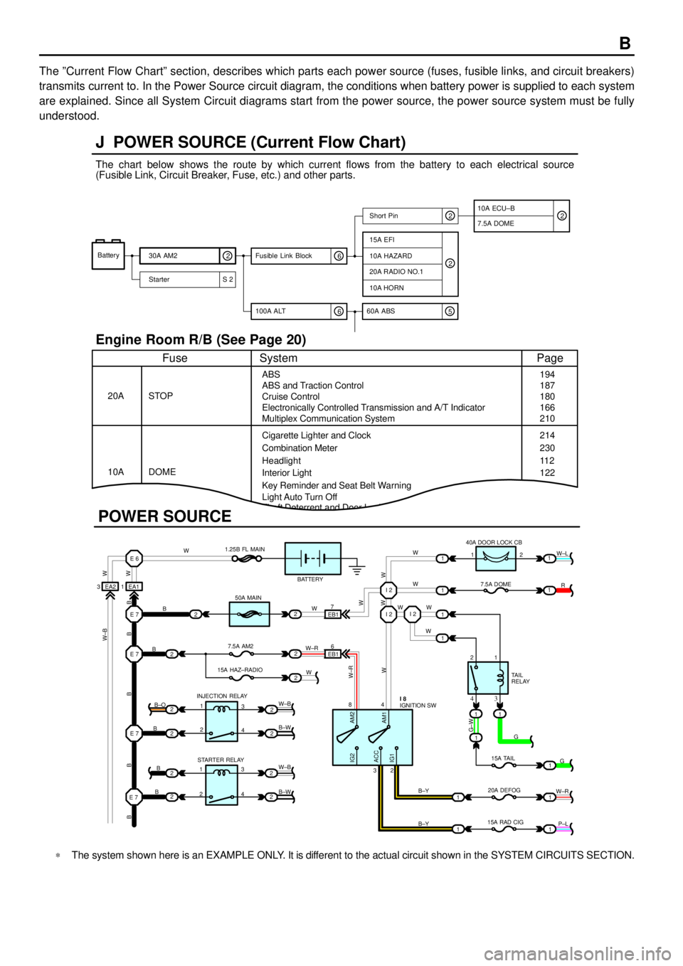
The ºCurrent Flow Chartº section, describes which parts each power source (fuses, fusible links, and circuit breakers)
transmits current to. In the Power Source circuit diagram, the conditions when battery power is supplied to each system
are explained. Since all System Circuit diagrams start from the power source, the power source system must be fully
understood.
Theft Deterrent and Door Lock Control
J POWER SOURCE (Current Flow Chart)
11
1
EA1 1EA2 3
7
EB16
E 6
E 7I 2I 2
I 2
E 7
E 7
E 7
2
1
1
2
2
2
2
2
B
B
W W
B B B B BW±B
B
B
B B±O
B±W
W±B
B±W STARTER RELAY INJECTION RELAY15A HAZ±RADIO7.5A AM250A MAIN 1.25B FL MAIN
BATTERY
WWW
W W W
R W±L
W
W
G±W
G
15A TAIL
20A DEFOG
15A RAD CIGTA I L
RELAY 7.5A DOME 40A DOOR LOCK CB
2 1
1 2
4 8
2 3
3 4
G
W±R
P±L B±Y
B±Y
W±R
AM2 IG2
ACC
IG1AM1W W
W±R
W W
W±B
21
1
1
1
1
2
2
2
2
3
4
3
4 1
2
1
22
1
11
1
IGNITION SW I 8
Battery
30A AM2
2
Starter S 220A RADIO NO.1
10A HORN
15A EFI
7.5A DOMEShort Pin
10A HAZARD
The chart below shows the route by which current flows from the battery to each electrical source
(Fusible Link, Circuit Breaker, Fuse, etc.) and other parts.
Engine Room R/B (See Page 20)
ABS
ABS and Traction Control
Cruise Control
Electronically Controlled Transmission and A/T Indicator
Multiplex Communication System
Cigarette Lighter and Clock
Key Reminder and Seat Belt Warning STOP
Fuse Page
194
214
11 2
System
DOME 20A
10ACombination Meter
Headlight
Interior Light
2
2
6 100A ALT
EB1
POWER SOURCE
Light Auto Turn Off187
180
166
210
230
122
10A ECU±B
5 60A ABS
2
6 Fusible Link Block2
*The system shown here is an EXAMPLE ONLY. It is different to the actual circuit shown in the SYSTEM CIRCUITS SECTION.
Page 4020 of 4592
![TOYOTA CAMRY 1999 Service Repair Manual B
[A]: Part Code
[B]: Part Name
[C]: Part Number
Toyota Part Number are indicated.
Not all of the above part numbers of the connector are established for the supply. In case of ordering a connector
or TOYOTA CAMRY 1999 Service Repair Manual B
[A]: Part Code
[B]: Part Name
[C]: Part Number
Toyota Part Number are indicated.
Not all of the above part numbers of the connector are established for the supply. In case of ordering a connector
or](/manual-img/14/57448/w960_57448-4019.png)
B
[A]: Part Code
[B]: Part Name
[C]: Part Number
Toyota Part Number are indicated.
Not all of the above part numbers of the connector are established for the supply. In case of ordering a connector
or terminal with wire, please confirm in advance if there is supply for it using
ªParts Catalog Newsº (published by
Parts Engineering Administration Dept.).
A 5�� ��
90980±11194
L PART NUMBER OF CONNECTORS
Code Part Name Part NumberCode Part NamePart Number
A 1
A 2
A 4
A 6
A 7A/C Ambient Temp. Sensor
A/C Condenser Fan Motor
A/C Triple Pressure SW (A/C Dual and
Single Pressure SW)
A/T Oil Temp. Sensor
ABS Actuator
ABS Actuator90980±11070
90980±11237
90980±10943
90980±11413
90980±11151D 4
D 5
D 6
D 7
D 8
D 9
D10
D11Diode (Door Courtesy Light)
Diode (Key Off Operation)
Diode (Luggage Compartment Light)
Door Lock Control Relay
Door Courtesy Light LH
Door Courtesy Light RH
Door Courtesy SW LH
Door Courtesy SW RH90980±11608
90980±10962
90980±11608
90980±10848
90980±11148
90980±11097
A 8ABS Speed Sensor Front LH
90980±10941
A 9ABS Speed Sensor Front RH
90980±11856 A10Airbag Sensor Front LH
A11Airbag Sensor Front RHD12Door Courtesy SW Front LH
90980±11156 D13Door Courtesy SW Front RH
D14Door Courtesy SW Rear LH
Door Courtesy SW Rear RH
D15
[B]�� ��[C]
A12
Auto Antenna Motor90980±11194 A 3
A/C Condenser Fan Relay90980±10940
[A]
90980±11009
90980±11002
D16
D17Door Key Lock and Unlock SW LH
Door Key Lock and Unlock SW RH90980±11170
Page 4041 of 4592

G ELECTRICAL WIRING ROUTING
Position of Parts in Body
A 19 ABS Speed Sensor Rear LH
A 20 ABS Speed Sensor Rear RH
B 5 Buckle SW LH
C 17 Condenser
D 7 Door Courtesy SW Front LH
D 8 Door Courtesy SW Front RH
D 9 Door Courtesy SW Rear LH
D 10 Door Courtesy SW Rear RH
D 11 Door Key Lock and Unlock SW Front LH
D 12 Door Key Lock and Unlock SW Front RH
D 13 Door Lock Control SW RH
D 14 Door Lock Motor and Door Unlock Detection SW
Front LH
D 15 Door Lock Motor and Door Unlock Detection SW
Front RH
D 16 Door Lock Motor and Door Unlock Detection SW
Rear LH
D 17 Door Lock Motor and Door Unlock Detection SW
Rear RHF 15 Front Door Speaker LH
F 16 Front Door Speaker RH
F 17 Fuel Temp. Sensor and Fuel Shutoff Valve (Fuel Tank)
H 8 High Mounted Stop Light
I 13 Interior Light
J 33 Junction Connector
J 34 Junction Connector
J 35 Junction Connector
L 1 License Plate Light LH
L 2 License Plate Light RH
L 3 Light Failure Sensor
L 4 Luggage Compartment Light
L 5 Luggage Compartment Light SW