Page 136 of 349
MX098–01
D06620
Clutch Release Fork Assembly
with Bearing
Clutch Release Fork SupportControl Lever Housing
Support Bracket
Boot
Clutch Release
Line Bracket
Transaxle Case
Transmission
Oil Cooler
Sub–AssemblyElbow
� O–Ring Vehicle Speed Sensor
Transaxle Case Receiver
Transmission Oil
PipeMagnet
Transmission
Oil Pipe
� Output Shaft Cover
Tapered Roller Bearing
Outer Race
� Front Oil Seal
Input Shaft Front
BearingTransmission Oil Pump
Assembly
Differential Case Assembly
Oil Pump Drive Gear
17 (175, 13)
47 (480, 35)
34 (350, 25)
27 (275, 20)
7.4 (75, 65 in.·lbf)
17 (175, 13)
17 (175, 13)
17 (175, 13)
17 (175, 13)
17 (175, 13)
N·m (kgf·cm, ft·lbf): Specified torque
� Non–reusable part� Gasket
� �
17 (175, 13)
– MANUAL TRANSAXLE (E251)MANUAL TRANSAXLE ASSEMBLY
MX–9
MANUAL TRANSAXLE ASSEMBLY
COMPONENTS
Page 139 of 349
MANUAL TRANSAXLE ASSEMBLY
DISASSEMBLY
1. REMOVE RELEASE FORK AND BEARING
2. REMOVE BACK–UP LIGHT SWITCH WITH GASKET
Torque: 40 N·m (")
MX099–01
Q05816
FIPG
Q00449
MX–12
– MANUAL TRANSAXLE (E251)MANUAL TRANSAXLE ASSEMBLY
DISASSEMBLY
1. REMOVE RELEASE FORK AND BEARING
2. REMOVE BACK–UP LIGHT SWITCH WITH GASKET
Torque: 40 N·m (410 kgf·cm, 30 ft·lbf)
3. REMOVE BOLT AND VEHICLE SPEED SENSOR
Torque: 17 N·m (175 kgf·cm, 13 ft·lbf)
4. REMOVE NO.2 SELECTING BELLCRANK WITH SE-
LECTING BELLCRANK SUPPORT
Remove the 2 bolts and No.2 selecting bellcrank with the se-
lecting bellcrank support.
Sealant:
Part No. 08833–00080, THREE BOND 1344, LOCTITE
242 or equivalent
Torque: 20 N·m (200 kgf·cm, 14 ft·lbf)
5. REMOVE SHIFT AND SELECT LEVER SHAFT LOCK
BOLT WITH GASKET
Torque: 49 N·m (500 kgf·cm, 36 ft·lbf)
6. REMOVE SHIFT AND SELECT LEVER SHAFT AS-
SEMBLY WITH GASKET
Remove the 4 bolts, the shift, select lever shaft assembly and
gasket.
Sealant:
Part No. 08833–00080, THREE BOND 1344, LOCTITE
242 or equivalent
Torque: 20 N·m (200 kgf·cm, 14 ft·lbf)
7. REMOVE TRANSMISSION CASE COVER
Remove the 10 bolts and transmission case cover.
FIPG:
Part No. 08826–00090, THREE BOND 1281 or equiva-
lent
Torque: 29 N·m (300 kgf·cm, 22 ft·lbf)
8. REMOVE BREATHER PLUG WITH GASKET
Torque: 49 N·m (500 kgf·cm, 36 ft·lbf)
9. REMOVE OUTPUT SHAFT LOCK NUT
(a) Remove the lock nut.
(b) Engage the gear double meshing.
(c) Remove the lock nut.
Torque: 123 N·m (1,250 kgf·cm, 90 ft·lbf)
(d) Disengage the gear double meshing.
10. REMOVE NO.3 HUB SLEEVE AND NO.3 SHIFT FORK
(a) Remove the No.3 shift fork set bolt.
Torque: 24 N·m (240 kgf·cm, 17 ft·lbf)
(b) Remove the No.3 hub sleeve and No.3 shift fork.
Page 168 of 349
MX060–02
D06656
Differential Spider
Differential Pinion
Differential Side Gear
Side Gear Thrust
Washer
Pinion Thrust Washer
� Tapered Roller Bearing
and Outer Race
Differential Right Case Vehicle Speed Sensor Drive Gear
Differential Left Case
� Tapered Roller Bearing
and Outer Race Ring Gear
Oil Baffle
� Oil Seal x16
Shim � Oil Seal
63 (640, 46)
N·m (kgf·cm, ft·lbf): Specified torque
� Non–reusable partx16
124 (1,260, 91)
– MANUAL TRANSAXLE (E251)DIFFERENTIAL CASE
MX–41
DIFFERENTIAL CASE
COMPONENTS
Page 169 of 349
DIFFERENTIAL CASE
DISASSEMBLY
NOTICE:
When working with FIPG material, you must observe the follow-
ing items.
�Using a razor")
MX09A–01
Q05166
SST
D06654
Matchmarks
MX–42
– MANUAL TRANSAXLE (E251)DIFFERENTIAL CASE
DISASSEMBLY
NOTICE:
When working with FIPG material, you must observe the follow-
ing items.
�Using a razor blade and gasket scraper, remove all the old
FIPG material from the gasket surfaces.
�Thoroughly clean all components to remove all the loose
material.
�Clean both sealing surfaces with a non–residue solvent.
�Apply FIPG in an approx. 1 mm (0.04 in.) wide bead along
the sealing surface.
�Parts must be assembled within 10 minutes of application.
Otherwise, the FIPG material must be removed and reap-
plied.
1. REMOVE TAPERED ROLLER BEARING
Using SST, remove the left and right bearings.
SST 09950–40011
2. REMOVE VEHICLE SPEED SENSOR DRIVE GEAR
FROM DIFFERENTIAL RIGHT CASE
3. REMOVE RING GEAR
(a) Place matchmarks on both the differential case and ring
gear.
(b) Remove the 16 bolts.
(c) Using a plastic hammer, tap the ring gear and remove it.
4. DISASSEMBLE DIFFERENTIAL CASE
(a) Place matchmarks on the differential right and left cases.
(b) Using a torx wrench (T50), remove the 16 torx screws.
(c) Using a plastic hammer, tap the differential left case.
Page 173 of 349
DIFFERENTIAL CASE
(b) Heat the ring gear to about 100�C (212�F� �� �������
�
�
��
(c) Carefully take the ring gear out of th")
Z00303
Driven Gear
Side
Q06410
SST
SST MX–46
– MANUAL TRANSAXLE (E251)DIFFERENTIAL CASE
(b) Heat the ring gear to about 100�C (212�F� �� �������
�
�
��
(c) Carefully take the ring gear out of the water.
(d) Clean the contact surface of the ring gear with cleaning
solvent.
(e) Quickly install the ring gear on the differential case.
HINT:
Align the matchmarks on the differential left case and contact
the ring gear.
(f) Temporarily install the 16 bolts.
NOTICE:
The ring gear set bolts should not be tightened until the
ring gear has cooled sufficiently.
(g) After the ring gear has cooled sufficiently, torque the ring
gear set bolts.
Torque: 124 N·m (1,260 kgf·cm, 91 ft·lbf)
3. INSTALL VEHICLE SPEED SENSOR DRIVE GEAR
4. INSTALL TAPERED ROLLER BEARING
Using SST and a press, install new left and right bearings onto
the differential case.
SST 09316–20011, 09316–60011 (09316–00011)
HINT:
Press the bearing on the ring side first.
5. ADJUST OUTPUT SHAFT ASSEMBLY PRELOAD
(See page MX–21)
6. INSTALL DIFFERENTIAL CASE ASSEMBLY TO
TRANSAXLE CASE
7. INSTALL OUTPUT SHAFT ASSEMBLY
Lift up the differential case and install the output shaft assem-
bly.
8. INSTALL TRANSMISSION CASE
(a) Install the transmission case.
HINT:
If necessary, tap on the case with a plastic hammer.
(b) Install and torque the 17 bolts.
Torque: 29 N·m (300 kgf·cm 22 ft·lbf)
9. INSTALL OUTPUT SHAFT REAR TAPERED ROLLER
BEARING OUTER RACE
Using a plastic hammer, drive in the outer race.
10. INSTALL SHIM (See page MX–21)
HINT:
Install the previously selected shim.
11. INSTALL REAR BEARING RETAINER
Using a torx wrench (T45), install and torque the 7 torx screws.
Torque: 42 N·m (430 kgf·cm, 31 ft·lbf)
Page 178 of 349
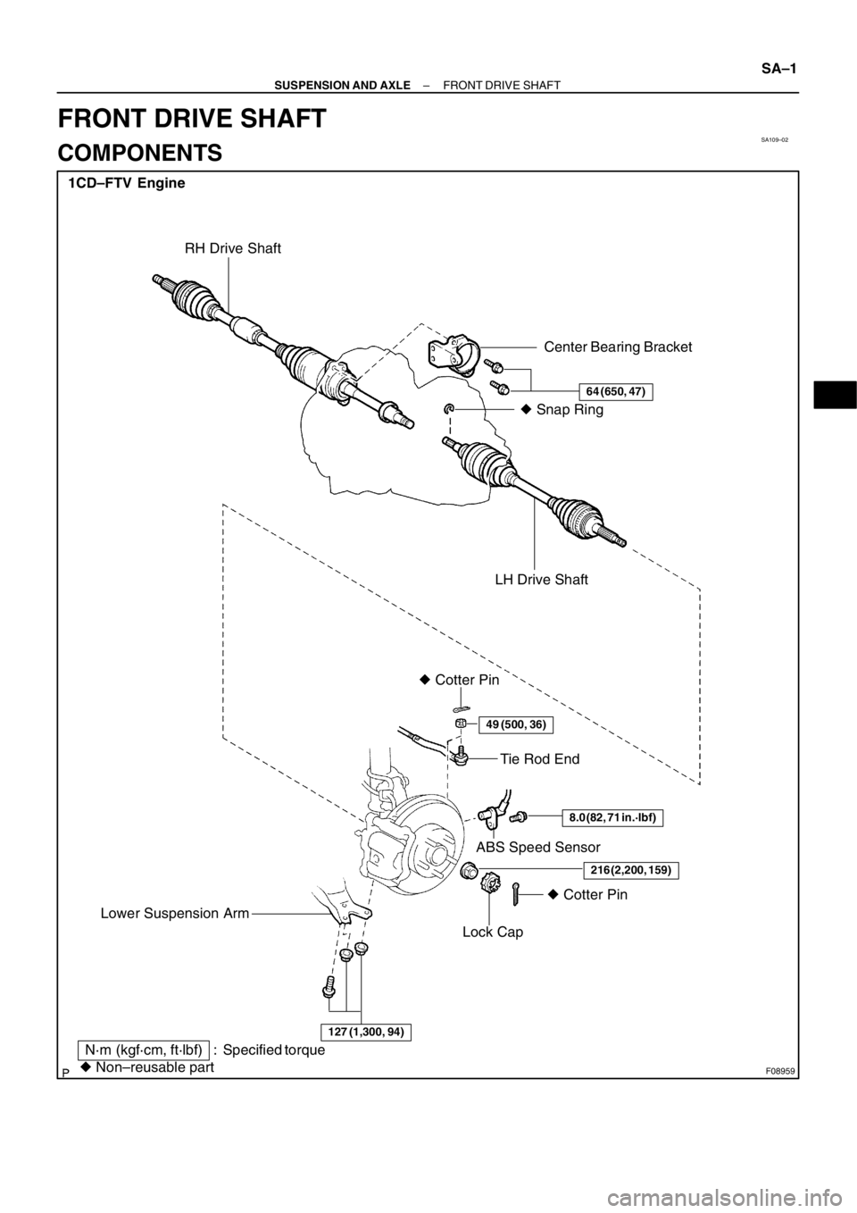
SA109–02
F08959
1CD–FTV Engine
Tie Rod End
ABS Speed Sensor � Cotter Pin
Lock Cap
� Non–reusable part
N·m (kgf·cm, ft·lbf) : Specified torqueLH Drive Shaft� Snap Ring
� Cotter Pin
Center Bearing Bracket
64 (650, 47)
49 (500, 36)
8.0 (82, 71 in.·lbf)
216 (2,200, 159)
RH Drive Shaft
127 (1,300, 94)
Lower Suspension Arm
– SUSPENSION AND AXLEFRONT DRIVE SHAFT
SA–1
FRONT DRIVE SHAFT
COMPONENTS
Page 180 of 349

SA10A–02
FA1535
SST
F02688
F02721
F02724
– SUSPENSION AND AXLEFRONT DRIVE SHAFT
SA–3
REMOVAL
NOTICE:
�The hub bearing could be damaged if it is subjected
to the vehicle weight, such as when moving the ve-
hicle with the drive shaft removed.
Therefore, if it is absolutely necessary to place the ve-
hicle weight on the hub bearing, first support it with
the SST.
SST 09608–16042 (09608–02021, 09608–02041)
�w/ ABS:
After disconnecting the drive shaft from the axle hub,
work carefully so as not to damage the ABS speed
sensor rotor serration on the drive shaft.
1. REMOVE FRONT WHEEL
2. DRAIN OUT GEAR OIL
3. w/ ABS:
REMOVE BOLT AND ABS SPEED SENSOR
4. REMOVE DRIVE SHAFT LOCK NUT
(a) Remove the cotter pin and lock cap.
(b) While applying the brakes, remove the nut.
5. DISCONNECT TIE ROD END FROM STEERING
KNUCKLE (See Pub. No. RM599E on page SA–11)
6. DISCONNECT LOWER BALL JOINT FROM LOWER
SUSPENSION ARM (See Pub. No. RM599E on page
SA–11)
7. DISCONNECT DRIVE SHAFT FROM AXLE HUB
(a) Using a plastic hammer, disconnect the drive shaft from
the axle hub.
NOTICE:
Cover the drive shaft boot and ABS speed sensor rotor with
cloth to protect it from being damaged.
(b) Push the front axle hub toward the outside of the vehicle
to separate the drive shaft from the axle hub.
8. REMOVE DRIVE SHAFTS
(a) RH drive shaft:
Remove the 2 bolts and pull out the drive shaft together
with the center bearing bracket.
Page 187 of 349
 Install a new snap ring to the inboard joint shaft.
(b) Coat the gear o")
SA02Z–03
SA–10
– SUSPENSION AND AXLEFRONT DRIVE SHAFT
INSTALLATION
1. LH drive shaft:
INSTALL DRIVE SHAFT TO TRANSAXLE
(a) Install a new snap ring to the inboard joint shaft.
(b) Coat the gear oil to the inboard joint shaft and differential case sliding surface.
(c) Set the snap ring with opening side facing downward.
(d) Using a brass bar and hammer, install the drive shaft.
NOTICE:
Be careful not to damage the dust cover of the drive shaft and oil seal lip of the transaxle.
HINT:
Whether the inboard joint shaft is in contact with the pinion shaft or not can be known from the sound or feel-
ing when driving it in.
(e) Check that there is 2 – 3 mm (0.08 – 0.12 in.) of play in the axial direction.
(f) Check that the drive shaft cannot be removed by hand.
2. RH drive shaft:
INSTALL DRIVE SHAFT TO TRANSAXLE
(a) Coat the gear oil to the inboard joint shaft and differential case sliding surface.
(b) Install the drive shaft with the center bearing bracket.
NOTICE:
Be careful not to damage the dust cover of the drive shaft and oil seal lip of the transaxle.
(c) Install the 2 bolts.
Torque: 64 N·m (650 kgf·cm, 47 ft·lbf)
3. CONNECT DRIVE SHAFT TO AXLE HUB
NOTICE:
Be careful not to damage the boot and ABS speed sensor rotor.
4. CONNECT LOWER SUSPENSION ARM TO LOWER BALL JOINT
Torque: 127 N·m (1,300 kgf·cm, 94 ft·lbf)
5. CONNECT TIE ROD END TO STEERING KNUCKLE
(a) Connect the tie rod end to the steering knuckle.
(b) Install the nut and a new cotter pin.
If the holes for the cotter pin are not aligned, tighten the nut further up to 60�.
Torque: 49 N·m (500 kgf·cm, 36 ft·lbf)
6. INSTALL DRIVE SHAFT LOCK NUT
(a) While applying brakes, install the nut.
Torque: 216 N·m (2,200 kgf·cm, 159 ft·lbf)
(b) Install the lock cap and a new cotter pin.
If the holes for the cotter pin are not aligned, tighten the nut further up to 60�.
7. w/ABS:
INSTALL ABS SPEED SENSOR AND BOLT
Torque: 8.0 N·m (82 kgf·cm, 71 in.·lbf)
8. FILL AND CHECK GEAR OIL (See page MX–4)
9. INSTALL FRONT WHEEL
Torque: 103 N·m (1,050 kgf·cm, 76 ft·lbf)
10. CHECK FRONT WHEEL ALIGNMENT (See Pub. No. RM599E on page SA–4)
11. CHECK ABS SPEED SENSOR SIGNAL (See Pub. No. RM599E on page DI–115)