Page 122 of 349

DI–30
– DIAGNOSTICSSUPPLEMENTAL RESTRAINT SYSTEM
4 Che")
� ����� ���
�����
������
������H11830
→←
E1Tc ACC ON
orAirbag
Sensor
Assembly
DTC 87 Check Connector Curtain
Shield
Airbag
Squib (LH)
DI–30
– DIAGNOSTICSSUPPLEMENTAL RESTRAINT SYSTEM
4 Check curtain shield airbag squib (LH).
PREPARATION:
(a) Turn ignition switch to LOCK.
(b) Disconnect negative (–) terminal cable from the battery,
and wait at least for 90 seconds.
(c) Connect the curtain shield airbag assembly (LH) connec-
tor.
(d) Connect negative (–) terminal cable to the battery, and
wait at least for 2 seconds.
CHECK:
(a) Turn ignition switch to LOCK, and wait at least for 20 se-
cond.
(b) Turn ignition switch to ACC or ON, and wait at least for 20
seconds.
(c) Clear DTC stored in memory.
(See page DI–153 of Pub. No. RM599E)
(d) Turn ignition switch to LOCK, and wait at least for 20 se-
conds.
(e) Turn ignition switch to ACC or ON, and wait at least for 20
seconds.
(f) Check DTC.
(See page DI–152 of Pub. No. RM599E)
OK:
DTC 87 is not output.
HINT:
Codes other than code 87 may be output at this time, but they
are not relevant to this check.
NG Replace curtain shield airbag assembly (LH).
OK
From the results of the above inspection, the malfunctioning part can now be considered normal.
To make sure of this, use the simulation method to check.
Page 123 of 349

ICL+
(–)(+)Airbag Sensor
Assembly
ICL–
– DIAGNOSTICSSUPPLEMENTAL RESTRAINT SYSTEM
DI–31
DTC 88 Open in Curtain Shi")
������������H11826
Airbag
Sensor
Assembly Curtain
Shield
Airbag
Squib (LH)
ICL+
(–)(+)Airbag Sensor
Assembly
ICL–
– DIAGNOSTICSSUPPLEMENTAL RESTRAINT SYSTEM
DI–31
DTC 88 Open in Curtain Shield Airbag Squib (LH)
Circuit
CIRCUIT DESCRIPTION
The curtain shield airbag squib circuit (LH) consists of the airbag sensor assembly and curtain shield airbag
assembly (LH).
It causes the curtain shield airbag assembly (LH) to activate when the curtain shield airbag assembly (LH)
activation conditions are satisfied.
For details of the function of each component, see OPERATION on page RS–2.
DTC 88 is recorded when an open is detected in the curtain shield airbag squib (LH) circuit.
DTC No.DTC Detecting ConditionTrouble Area
88
�Open circuit in ICL+ wire harness or ICL– wire harness of
squib
�Curtain shield airbag squib (LH) malfunction
�Airbag sensor assembly malfunction�Curtain shield airbag assembly (LH)
�Airbag sensor assembly
�Wire harness
WIRING DIAGRAM
See page DI–21.
INSPECTION PROCEDURE
1 Prepare for inspection. (See step 1 on page DI–285 of Pub. No. RM599E)
2 Check curtain shield airbag squib (LH) circuit.
CHECK:
For the connector (on the curtain shield airbag assembly side)
between the curtain shield airbag assembly (LH) and the airbag
sensor assembly, measure the resistance between ICL+ and
ICL–.
OK:
Resistance: Below 1 Ω
NG Repair or replace harness or connector be-
tween curtain shield airbag assembly (LH) and
airbag sensor assembly.
DI69E–01
Page 124 of 349

ICL+
ICL–ACC
orON
DI–32
– DIAGNOSTICSSUPPLEMENTAL R")
� ���� � ���
�����
������
�����
������
H11831
Airbag
Sensor
Assembly
DTC 88
E1 Tc Check Connector→ ← Curtain
Shield
Airbag
Squib (LH)
ICL+
ICL–ACC
orON
DI–32
– DIAGNOSTICSSUPPLEMENTAL RESTRAINT SYSTEM
OK
3 Check airbag sensor assembly.
PREPARATION:
(a) Connect the connector to the airbag sensor assembly.
(b) Using a service wire, connect ICL+ and ICL– of the con-
nector (on the curtain shield airbag assembly side) be-
tween the curtain shield airbag assembly (LH) and airbag
sensor assembly.
(c) Connect negative (–) terminal cable to the battery, and
wait at least for 2 seconds.
CHECK:
(a) Turn ignition switch to ACC or ON and wait at least for 20
seconds.
(b) Clear DTC stored in memory.
(See page DI–153 of Pub. No. RM599E)
(c) Turn ignition switch to LOCK, and wait at least for 20 se-
conds.
(d) Turn ignition switch to ACC or ON, and wait at least for 20
seconds.
(e) Check DTC.
(See page DI–152 of Pub. No. RM599E)
OK:
DTC 88 is not output.
HINT:
Codes other than code 88 may be output at this time, but they
are not relevant to this check.
NG Replace airbag sensor assembly.
OK
Page 125 of 349

– DIAGNOSTICSSUPPLEMENTAL RESTRAINT SYSTEM
DI–33
4 Chec")
� ����� ���
�����
������
�����
H11832
→←
E1Tc ACC ON
orAirbag
Sensor
Assembly
DTC 88 Check ConnectorCurtain
Shield
Airbag
Squib (LH)
– DIAGNOSTICSSUPPLEMENTAL RESTRAINT SYSTEM
DI–33
4 Check curtain shield airbag squib (LH).
PREPARATION:
(a) Turn ignition switch to LOCK.
(b) Disconnect negative (–) terminal cable from the battery,
and wait at least for 90 seconds.
(c) Connect the curtain shield airbag assembly (LH) connec-
tor.
(d) Connect negative (–) terminal cable to the battery, and
wait at least for 2 seconds.
CHECK:
(a) Turn ignition switch to ACC or ON, and wait at least for 20
seconds.
(b) Clear DTC stored in memory.
(See page DI–153 of Pub. No. RM599E)
(c) Turn ignition switch to LOCK, and wait at least for 20 se-
conds.
(d) Turn ignition switch to ACC or ON, and wait at least for 20
seconds.
(e) Check DTC.
(See page DI–152 of Pub. No. RM599E)
OK:
DTC 88 is not output.
HINT:
Codes other than code 88 may be output at this time, but they
are not relevant to this check.
NG Replace curtain shield airbag assembly (LH).
OK
From the results of the above inspection, the malfunctioning part can now be considered normal.
To make sure of this, use the simulation method to check.
Page 129 of 349
MX096–02
D06619
Starter
39 (400, 29)
Clutch Release
Cylinder
and Line
12 (120, 9)
4.9 (50, 43 in.·lbf)
12 (120, 9)
Control CableClip
Clip
Washer Air Flow Meter
ConnectorAir Cleaner Case
Assembly
with Air Hose
52 (530, 38)
87 (890, 64)
Engine Left
Mounting Bracket
Battery
Tray
No.1 Air Tube Assembly
Diesel Throttle Body
with No.2 Air Tube Assembly
Stay
VSV Connector for EGR
Turbo Pressure
Sensor Connector
Intake Air Temperature
Sensor Connector
Throttle Full
Switch Connector
Throttle Control
Motor Connector
� Gasket
� Non–reusable part
21 (214, 15)
N·m (kgf·cm, ft·lbf): Specified torque
15 (153, 11)
25 (255, 18)
25 (255, 18)
25 (255, 18)
25 (255, 18)
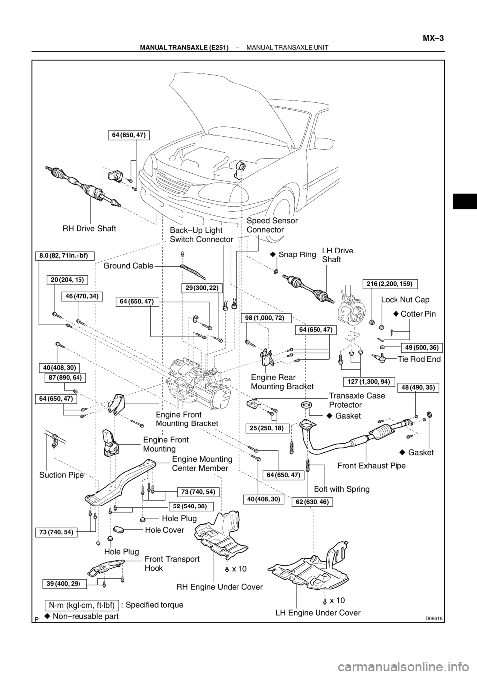
MX–2
– MANUAL TRANSAXLE (E251)MANUAL TRANSAXLE UNIT
MANUAL TRANSAXLE UNIT
COMPONENTS
Page 130 of 349
D06618
RH Drive Shaft
LH Drive
Shaft
216 (2,200, 159)
Lock Nut Cap
� Cotter Pin � Snap Ring
Front Exhaust Pipe
Engine Mounting
Center Member
LH Engine Under Cover RH Engine Under Cover
64 (650, 47)
Transaxle Case
Protector
25 (250, 18)
Back–Up Light
Switch Connector
Speed Sensor
Connector
Front Transport
HookHole Plug
Hole PlugHole Cover
64 (650, 47)
39 (400, 29)
73 (740, 54)
73 (740, 54)
52 (540, 38)
Tie Rod End
Engine Rear
Mounting Bracket
64 (650, 47)
98 (1,000, 72)
29 (300, 22)
64 (650, 47)
49 (500, 36)
127 (1,300, 94)
Ground Cable
Engine Front
Mounting Bracket
Engine Front
Mounting
Suction Pipe
N·m (kgf·cm, ft·lbf): Specified torque
� Non–reusable part� Gasket � Gasket
8.0 (82, 71in.·lbf)
40 (408, 30)
x 10Bolt with Spring
20 (204, 15)
46 (470, 34)
62 (630, 46)
48 (490, 35)
40 (408, 30)
87 (890, 64)
64 (650, 47)
x 10
– MANUAL TRANSAXLE (E251)MANUAL TRANSAXLE UNIT
MX–3
Page 131 of 349
(b)
D06627
D06628
MX–4
– MANUAL TRANSAXLE (E251)MANUAL TRANSAXLE UNIT
REMOVAL
1. REMOVE BATTERY AND TRAY
2. REMOVE AIR CLEANER CASE ASSEMBLY WITH AIR
HOSE
3. REMOVE LH AND RH")
MX097–02
D06626
(a)(b)
D06627
D06628
MX–4
– MANUAL TRANSAXLE (E251)MANUAL TRANSAXLE UNIT
REMOVAL
1. REMOVE BATTERY AND TRAY
2. REMOVE AIR CLEANER CASE ASSEMBLY WITH AIR
HOSE
3. REMOVE LH AND RH ENGINE UNDER COVERS
4. REMOVE NO.1 AIR TUBE ASSEMBLY
(a) Disconnect the No.2 vacuum hose from the E–VRV for
EGR.
(b) Disconnect the No.2 vacuum hose from the VSV for EGR.
(c) Disconnect the VSV connector for EGR.
(d) Disconnect the turbo pressure sensor connector and vac-
uum hose.
(e) Remove the 2 bolts as shown in the illustration.
Torque: 25 N·m (255 kgf·cm, 18 ft·lbf)
(f) Disconnect the 2 hose clips, and remove the No.1 air tube
assembly.
5. REMOVE DIESEL THROTTLE BODY WITH NO.2 AIR
TUBE ASSEMBLY
(a) Disconnect the intake air temperature sensor connector.
(b) Disconnect the throttle control motor connector.
(c) Disconnect the full opener switch connector.
(d) Remove the 3 bolts from the diesel throttle body.
Torque: 21 N·m (214 kgf·cm, 15 ft·lbf)
(e) Remove the 2 bolts as shown in the illustration.
Torque: 25 N·m (255 kgf·cm, 18 ft·lbf)
(f) Disconnect the 2 hose clips, and remove the diesel
throttle body assembly with the No.2 air tube assembly.
Page 132 of 349
MANUAL TRANSAXLE UNIT
MX–5
6. REMOVE STARTER
(a) Remove the 2 bolts and disconnect the radiator reservoir
from the radiator.
(b")
D06629
D06639
A
B
D06633
D06636
B AA
D06634
– MANUAL TRANSAXLE (E251)MANUAL TRANSAXLE UNIT
MX–5
6. REMOVE STARTER
(a) Remove the 2 bolts and disconnect the radiator reservoir
from the radiator.
(b) Disconnect the starter connector.
(c) Remove the nut, and disconnect the starter wire.
Torque: 15 N·m (153 kgf·cm, 11 ft·lbf)
(d) Remove the 2 bolts and starter.
Torque: 39 N·m (400 kgf·cm, 29 ft·lbf)
7. DISCONNECT CLUTCH RELEASE CYLINDER AND
LINE
(a) Remove the 2 set bolts of the clutch line bracket.
Torque:
Bolt A: 12 N·m (120 kgf·cm, 9 ft·lbf)
Bolt B: 4.9 N·m (50 kgf·cm, 43 in.·lbf)
(b) Remove the 2 bolts and disconnect the release cylinder
and line.
Torque: 12 N·m (120 kgf·cm, 9 ft·lbf)
8. DISCONNECT GROUND CABLE
Remove the set bolt of the ground cable from the transaxle.
9. DISCONNECT VEHICLE SPEED SENSOR AND
BACK–UP LIGHT SWITCH CONNECTORS
10. DISCONNECT CONTROL CABLE
(a) Remove the 2 clips and washers.
(b) Remove the 2 clips from the cables.
11. REMOVE 4 TRANSAXLE UPPER SIDE MOUNTING
BOLTS
Torque:
Bolt A: 64 N·m (650 kgf·cm, 47 ft·lbf)
Bolt B: 29 N·m (296 kgf·cm, 21 ft·lbf)
12. INSTALL ENGINE SUPPORT FIXTURE
Install the engine hanger in the correct direction.
Parts No.:
Engine hanger: 12281–27010
Bolt: 96122–61020
Torque: 37 N·m (377 kgf·cm, 27 ft·lbf)

Clutch Release
Cylinder
and Line
12 (120, 9)
4.9 (50, 43 in.·lbf)
12 (120, 9)
Control CableClip
Clip
Washer Air Flow Meter
ConnectorAir Cleaner Case
Assembly")