1999 SUZUKI GRAND VITARA regulator
[x] Cancel search: regulatorPage 165 of 656

6-1-4 ENGINE GENERAL INFORMATION AND DIAGNOSIS (H27 ENGINE)
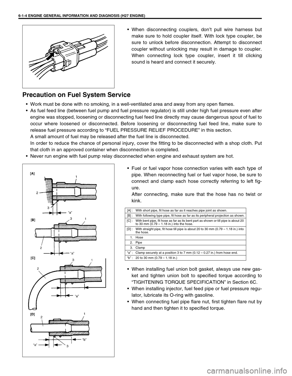
When disconnecting couplers, don’t pull wire harness but
make sure to hold coupler itself. With lock type coupler, be
sure to unlock before disconnection. Attempt to disconnect
coupler without unlocking may result in damage to coupler.
When connecting lock type coupler, insert it till clicking
sound is heard and connect it securely.
Precaution on Fuel System Service
Work must be done with no smoking, in a well-ventilated area and away from any open flames.
As fuel feed line (between fuel pump and fuel pressure regulator) is still under high fuel pressure even after
engine was stopped, loosening or disconnecting fuel feed line directly may cause dangerous spout of fuel to
occur where loosened or disconnected. Before loosening or disconnecting fuel feed line, make sure to
release fuel pressure according to “FUEL PRESSURE RELIEF PROCEDURE” in this section.
A small amount of fuel may be released after the fuel line is disconnected.
In order to reduce the chance of personal injury, cover the fitting to be disconnected with a shop cloth. Put
that cloth in an approved container when disconnection is completed.
Never run engine with fuel pump relay disconnected when engine and exhaust system are hot.
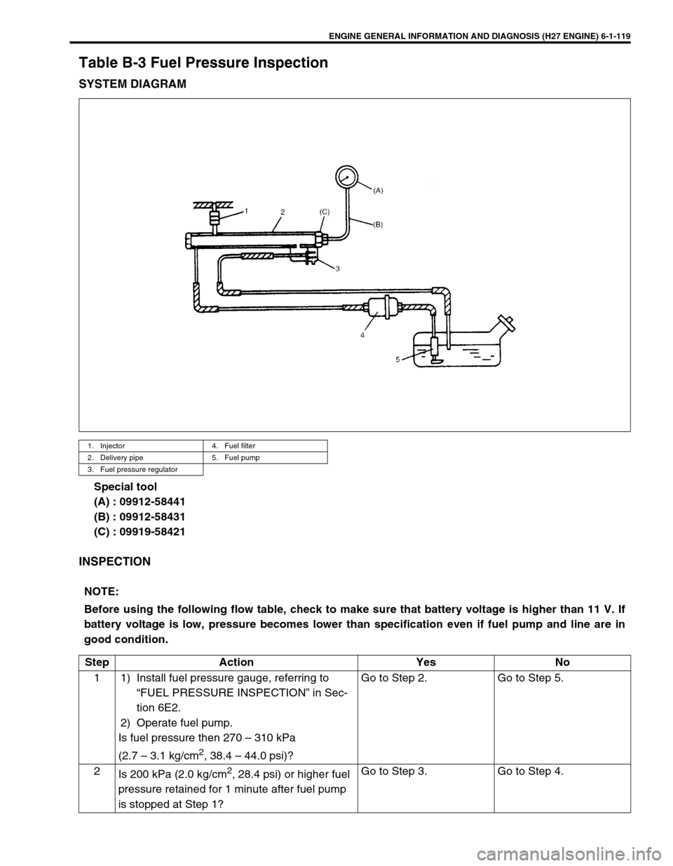
Fuel or fuel vapor hose connection varies with each type of
pipe. When reconnecting fuel or fuel vapor hose, be sure to
connect and clamp each hose correctly referring to left fig-
ure.
After connecting, make sure that the hose has no twist or
kink.
When installing fuel union bolt gasket, always use new gas-
ket and tighten union bolt to specified torque according to
“TIGHTENING TORQUE SPECIFICATION” in Section 6C.
When installing injector, fuel feed pipe or fuel pressure regu-
lator, lubricate its O-ring with gasoline.
When connecting fuel pipe flare nut, first tighten flare nut by
hand and then tighten it to specified torque.
[A] : With short pipe, fit hose as far as it reaches pipe joint as shown.
[B] : With following type pipe, fit hose as far as its peripheral projection as shown.
[C] : With bent pipe, fit hose as far as its bent part as shown or till pipe is about 20
to 30 mm (0.79 – 1.18 in.) into the hose.
[D] : With straight pipe, fit hose till pipe is about 20 to 30 mm (0.79 – 1.18 in.) into
the hose.
1. Hose
2. Pipe
3. Clamp
“a” : Clamp securely at a position 3 to 7 mm (0.12 – 0.27 in.) from hose end.
“b” : 20 to 30 mm (0.79 – 1.18 in.)
Page 192 of 656

ENGINE GENERAL INFORMATION AND DIAGNOSIS (H27 ENGINE) 6-1-31
Engine Diagnosis Table
Perform troubleshooting referring to following table when ECM (PCM) has detected no DTC and no abnormality
has been found in visual inspection and engine basic inspection previously.
Condition Possible Cause Correction
Hard starting
(Engine cranks OK)Faulty idle air control system “DIAG. FLOW TABLE B-4” in this
section.
Faulty ECT sensor or MAF sensor ECT sensor or MAF sensor in Sec-
tion 6E2.
Faulty ECM (PCM) Inspection of ECM (PCM) and its
circuit in this section.
Low compression Compression check in Section
6A2.
Faulty hydraulic valve lash adjuster Valve lash adjuster in Section 6A2.
Compression leak from valve seat Valves inspection in Section 6A2.
Sticky valve stem Valves inspection in Section 6A2.
Weak or damaged valve springs Valves spring inspection in Section
6A2.
Compression leak at cylinder head gasket Cylinder head inspection in Section
6A2.
Sticking or damaged piston ring Piston ring inspection in Section
6A2.
Worn piston, ring or cylinder Cylinders, pistons and piston rings
inspection in Section 6A2.
Malfunctioning PCV valve PCV system inspection in Section
6E2.
Engine has no power
Engine overheating Refer to “OVERHEATING” in this
table.
Defective spark plug Spark plugs in Section 6F2.
Faulty ignition coil with ignitor Ignition coil in Section 6F2.
Fuel pressure out of specification
(dirty fuel filter, dirty or clogged fuel hose or
pipe, malfunctioning fuel pressure regulator,
malfunctioning fuel pump)“DIAG. FLOW TABLE B-3” in this
section.
Maladjusted TP sensor installation angle TP sensor in Section 6E2.
Faulty EGR system “DTC P0400 DIAG. FLOW TABLE”
in this section.
Faulty injector Fuel injector in Section 6E2.
Faulty TP sensor, ECT sensor or MAF sensor TP sensor, ECT sensor or MAF
sensor in Section 6E2.
Faulty ECM (PCM) Inspection of ECM (PCM) and its
circuit in this section.
Low compression Refer to the same item in “HARD
STARTING” of this table.
Dragging brakes Diagnosis in Section 5.
Slipping clutch Diagnosis in Section 7C1.
Page 194 of 656

ENGINE GENERAL INFORMATION AND DIAGNOSIS (H27 ENGINE) 6-1-33
Surges
(Engine power varia-
tion under steady
throttle or cruise.
Feels like the vehicle
speeds up and down
with no change in the
accelerator pedal.)Defective spark plug
(excess carbon deposits, improper gap, and
burned electrodes, etc.)Spark plugs in Section 6F2.
Variable fuel pressure
(clogged fuel filter, kinky or damaged fuel hose
and line, faulty fuel pressure regulator)“DIAG. FLOW TABLE B-3” in this
section.
Faulty EGR system “DTC P0400 DIAG. FLOW TABLE”
in this section.
Faulty MAF sensor MAF sensor in Section 6E2.
Faulty injector Fuel injector in Section 6E2.
Faulty ECM (PCM) Inspection of ECM (PCM) and its
circuit in this section.
Excessive detonation
(The engine makes
sharp metallic knocks
that change with throt-
tle opening. Sounds
like pop corn pop-
ping.)Engine overheating Refer to “OVERHEATING” in this
table.
Faulty spark plug Spark plugs in Section 6F2.
Improper ignition timing Ignition timing in Section 6F2.
Clogged fuel filter and fuel lines Fuel pressure check in Section
6E2.
Faulty EGR system “DTC P0400 DIAG. FLOW TABLE”
in this section.
Faulty ECT sensor or MAF sensor ECT sensor or MAF sensor in Sec-
tion 6E2.
Faulty injector Fuel injector in Section 6E2.
Faulty ECM (PCM) Inspection of ECM (PCM) and its
circuit in this section.
Excessive carbon deposits in combustion
chamberPiston and cylinder head cleaning
in Section 6A2.
Poor knock sensor performance “DTC P0325 DIAG. FLOW TABLE”
in this section.
Overheating
Inoperative thermostat Thermostat in Section 6B.
Poor water pump performance Water pump in Section 6B.
Clogged or leaky radiator Radiator in Section 6B.
Improper engine oil grade Engine oil and oil filter change in
Section 0B.
Clogged oil filter or oil strainer Oil pressure check in Section 6A2.
Poor oil pump performance Oil pressure check in Section 6A2.
Dragging brakes Diagnosis in Section 5.
Slipping clutch Diagnosis in Section 7C1.
Blown cylinder head gasket Cylinder head inspection in Section
6A2. Condition Possible Cause Correction
Page 280 of 656

ENGINE GENERAL INFORMATION AND DIAGNOSIS (H27 ENGINE) 6-1-119
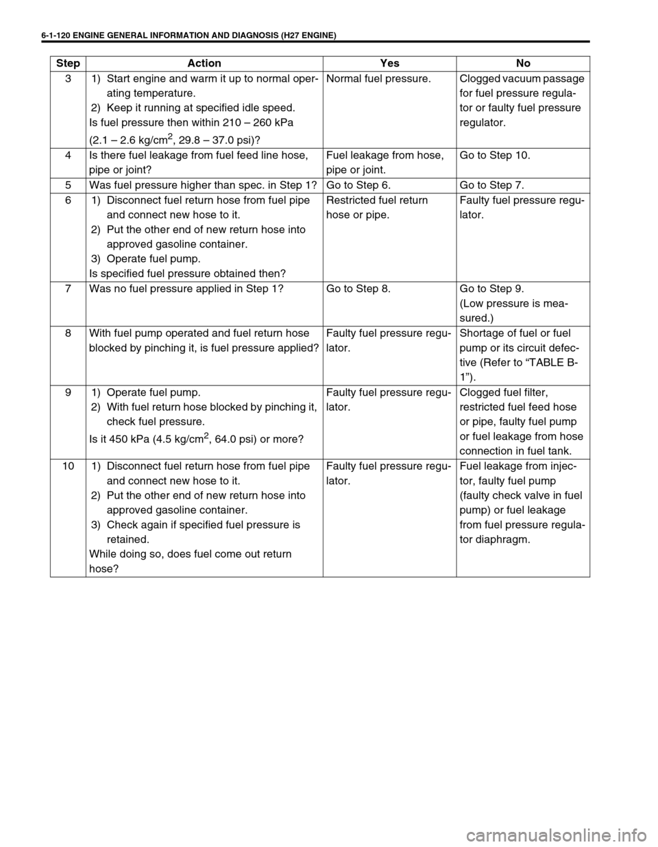
Table B-3 Fuel Pressure Inspection
SYSTEM DIAGRAM
Special tool
(A) : 09912-58441
(B) : 09912-58431
(C) : 09919-58421
INSPECTION
1. Injector 4. Fuel filter
2. Delivery pipe 5. Fuel pump
3. Fuel pressure regulator
NOTE:
Before using the following flow table, check to make sure that battery voltage is higher than 11 V. If
battery voltage is low, pressure becomes lower than specification even if fuel pump and line are in
good condition.
Step Action Yes No
1 1) Install fuel pressure gauge, referring to
“FUEL PRESSURE INSPECTION” in Sec-
tion 6E2.
2) Operate fuel pump.
Is fuel pressure then 270 – 310 kPa
(2.7 – 3.1 kg/cm
2, 38.4 – 44.0 psi)?Go to Step 2. Go to Step 5.
2
Is 200 kPa (2.0 kg/cm
2, 28.4 psi) or higher fuel
pressure retained for 1 minute after fuel pump
is stopped at Step 1?Go to Step 3. Go to Step 4.
Page 281 of 656

6-1-120 ENGINE GENERAL INFORMATION AND DIAGNOSIS (H27 ENGINE)
3 1) Start engine and warm it up to normal oper-
ating temperature.
2) Keep it running at specified idle speed.
Is fuel pressure then within 210 – 260 kPa
(2.1 – 2.6 kg/cm
2, 29.8 – 37.0 psi)?Normal fuel pressure. Clogged vacuum passage
for fuel pressure regula-
tor or faulty fuel pressure
regulator.
4 Is there fuel leakage from fuel feed line hose,
pipe or joint?Fuel leakage from hose,
pipe or joint.Go to Step 10.
5 Was fuel pressure higher than spec. in Step 1? Go to Step 6. Go to Step 7.
6 1) Disconnect fuel return hose from fuel pipe
and connect new hose to it.
2) Put the other end of new return hose into
approved gasoline container.
3) Operate fuel pump.
Is specified fuel pressure obtained then?Restricted fuel return
hose or pipe.Faulty fuel pressure regu-
lator.
7 Was no fuel pressure applied in Step 1? Go to Step 8. Go to Step 9.
(Low pressure is mea-
sured.)
8 With fuel pump operated and fuel return hose
blocked by pinching it, is fuel pressure applied?Faulty fuel pressure regu-
lator.Shortage of fuel or fuel
pump or its circuit defec-
tive (Refer to “TABLE B-
1”).
9 1) Operate fuel pump.
2) With fuel return hose blocked by pinching it,
check fuel pressure.
Is it 450 kPa (4.5 kg/cm
2, 64.0 psi) or more?Faulty fuel pressure regu-
lator.Clogged fuel filter,
restricted fuel feed hose
or pipe, faulty fuel pump
or fuel leakage from hose
connection in fuel tank.
10 1) Disconnect fuel return hose from fuel pipe
and connect new hose to it.
2) Put the other end of new return hose into
approved gasoline container.
3) Check again if specified fuel pressure is
retained.
While doing so, does fuel come out return
hose?Faulty fuel pressure regu-
lator.Fuel leakage from injec-
tor, faulty fuel pump
(faulty check valve in fuel
pump) or fuel leakage
from fuel pressure regula-
tor diaphragm. Step Action Yes No
Page 334 of 656

ENGINE AND EMISSION CONTROL SYSTEM (SEQUENTIAL MULTIPORT FUEL INJECTION FOR H27 ENGINE) 6E2-1
6E2
SECTION 6E2
ENGINE AND EMISSION CONTROL SYSTEM
(SEQUENTIAL MULTIPORT FUEL INJECTION
FOR H27 ENGINE)
CONTENTS
General Description ..................................... 6E2-2
System Flow ............................................... 6E2-3
System Diagram ......................................... 6E2-4
Air Intake System ....................................... 6E2-6
Fuel Delivery System ................................. 6E2-7
Electronic Control System .......................... 6E2-8
Engine and Emission Control Input/Output
Table ........................................................ 6E2-12
Diagnosis .................................................... 6E2-12
On-Vehicle Service..................................... 6E2-13
General .................................................... 6E2-13
Accelerator Cable Adjustment .................. 6E2-14
A/T Throttle Cable Adjustment
(A/T Vehicle) ............................................ 6E2-14Idle Speed/Idle Air Control (IAC) Duty
Inspection................................................. 6E2-15
[Using SUZUKI scan tool] .................... 6E2-15
[Not using SUZUKI scan tool]
(vehicle with monitor connector) .......... 6E2-16
Idle mixture inspection/adjustment
(vehicle without heated oxygen sensor) 6E2-17
Air Intake System ..................................... 6E2-18
Throttle body ........................................ 6E2-18
Idle air control valve (IAC valve) .......... 6E2-21
Fast idle air valve ................................. 6E2-22
Fuel Delivery System ............................... 6E2-23
Fuel pressure inspection ...................... 6E2-23
Fuel pump ............................................ 6E2-24
Fuel pressure regulator ........................ 6E2-25 WARNING:
For vehicles equipped with Supplemental Restraint (Air Bag) System:
Service on and around the air bag system components or wiring must be performed only by an
authorized SUZUKI dealer. Refer to “Air Bag System Components and Wiring Location View” under
“General Description” in air bag system section in order to confirm whether you are performing ser-
vice on or near the air bag system components or wiring. Please observe all WARNINGS and “Ser-
vice Precautions” under “On-Vehicle Service” in air bag system section before performing service
on or around the air bag system components or wiring. Failure to follow WARNINGS could result in
unintentional activation of the system or could render the system inoperative. Either of these two
conditions may result in severe injury.
Technical service work must be started at least 90 seconds after the ignition switch is turned to the
“LOCK” position and the negative cable is disconnected from the battery. Otherwise, the system
may be activated by reserve energy in the Sensing and Diagnostic Module (SDM).
NOTE:
Whether following systems (parts) are used in the particular vehicle or not depends on specifications.
Be sure to bear this in mind when performing service work.
Monitor connector
CKP sensor
MAP sensor
EGR valve
Heated oxygen sensor or CO adjusting resistor
Three way catalytic converter, Warm-up three way catalytic converter
Page 335 of 656

6E2-2 ENGINE AND EMISSION CONTROL SYSTEM (SEQUENTIAL MULTIPORT FUEL INJECTION FOR H27 ENGINE)
Fuel injector.......................................... 6E2-26
Electronic Control System........................ 6E2-31
Engine control module (ECM)/
powertrain control module (PCM) ........ 6E2-31
Mass air flow sensor (MAF sensor)...... 6E2-32
Intake air temperature (IAT) sensor ..... 6E2-34
Throttle position sensor (TP sensor) .... 6E2-35
Engine coolant temperature sensor
(ECT sensor) ........................................ 6E2-36
Heated oxygen sensor (sensor 1) ........ 6E2-37
Heated oxygen sensor (sensor 2) ........ 6E2-38
Vehicle speed sensor (VSS) ................ 6E2-39
Manifold absolute pressure sensor ...... 6E2-39
Fuel level sensor (sender gauge)......... 6E2-41
Crankshaft position sensor................... 6E2-41Main relay ............................................ 6E2-41
Fuel pump relay ................................... 6E2-42
Fuel cut operation ................................ 6E2-43
Emission Control System......................... 6E2-44
EGR system (if equipped) .................... 6E2-44
EVAP canister ...................................... 6E2-45
Vacuum passage ................................. 6E2-46
PCV System ............................................ 6E2-47
PCV hose ............................................. 6E2-47
PCV valve ............................................ 6E2-47
PCV system ......................................... 6E2-48
Tightening Torque Specification.............. 6E2-48
Special Tool ............................................... 6E2-48
General Description
The engine and emission control system has 4 major sub-systems: air intake system, fuel delivery system, elec-
tronic control system and emission control system.
Air intake system includes air cleaner, mass air flow sensor, throttle body, idle air control valve and intake man-
ifold.
Fuel delivery system includes fuel pump, delivery pipe, fuel pressure regulator, fuel injectors, etc.
Electronic control system includes ECM (PCM), various sensors and controlled devices.
Emission control system includes EGR, EVAP and PCV systems.
Page 338 of 656

ENGINE AND EMISSION CONTROL SYSTEM (SEQUENTIAL MULTIPORT FUEL INJECTION FOR H27 ENGINE) 6E2-5
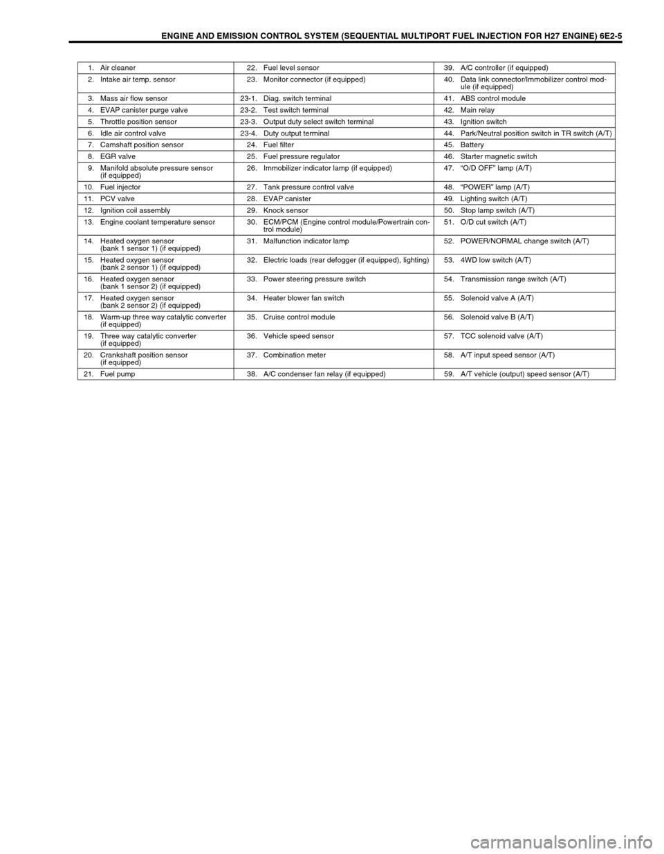
1. Air cleaner 22. Fuel level sensor 39. A/C controller (if equipped)
2. Intake air temp. sensor 23. Monitor connector (if equipped) 40. Data link connector/Immobilizer control mod-
ule (if equipped)
3. Mass air flow sensor 23-1. Diag. switch terminal 41. ABS control module
4. EVAP canister purge valve 23-2. Test switch terminal 42. Main relay
5. Throttle position sensor 23-3. Output duty select switch terminal 43. Ignition switch
6. Idle air control valve 23-4. Duty output terminal 44. Park/Neutral position switch in TR switch (A/T)
7. Camshaft position sensor 24. Fuel filter 45. Battery
8. EGR valve 25. Fuel pressure regulator 46. Starter magnetic switch
9. Manifold absolute pressure sensor
(if equipped)26. Immobilizer indicator lamp (if equipped) 47.“O/D OFF” lamp (A/T)
10. Fuel injector 27. Tank pressure control valve 48.“POWER” lamp (A/T)
11. PCV valve 28. EVAP canister 49. Lighting switch (A/T)
12. Ignition coil assembly 29. Knock sensor 50. Stop lamp switch (A/T)
13. Engine coolant temperature sensor 30. ECM/PCM (Engine control module/Powertrain con-
trol module)51. O/D cut switch (A/T)
14. Heated oxygen sensor
(bank 1 sensor 1) (if equipped)31. Malfunction indicator lamp 52. POWER/NORMAL change switch (A/T)
15. Heated oxygen sensor
(bank 2 sensor 1) (if equipped)32. Electric loads (rear defogger (if equipped), lighting) 53. 4WD low switch (A/T)
16. Heated oxygen sensor
(bank 1 sensor 2) (if equipped)33. Power steering pressure switch 54. Transmission range switch (A/T)
17. Heated oxygen sensor
(bank 2 sensor 2) (if equipped)34. Heater blower fan switch 55. Solenoid valve A (A/T)
18. Warm-up three way catalytic converter
(if equipped)35. Cruise control module 56. Solenoid valve B (A/T)
19. Three way catalytic converter
(if equipped)36. Vehicle speed sensor 57. TCC solenoid valve (A/T)
20. Crankshaft position sensor
(if equipped)37. Combination meter 58. A/T input speed sensor (A/T)
21. Fuel pump 38. A/C condenser fan relay (if equipped) 59. A/T vehicle (output) speed sensor (A/T)