1999 SUZUKI GRAND VITARA ACCELERATOR CABLE
[x] Cancel search: ACCELERATOR CABLEPage 174 of 656
ENGINE GENERAL INFORMATION AND DIAGNOSIS (H27 ENGINE) 6-1-13
STEP 2. DIAGNOSTIC TROUBLE CODE (DTC)/FREEZE FRAME DATA CHECK
First, check DTC, referring to “DIAGNOSTIC TROUBLE CODE CHECK” in this section. If DTC is indicated,
record DTC and freeze frame data.
After that clear DTC referring to “DIAGNOSTIC TROUBLE CODE CLEARANCE” in this section. DTC indicates
malfunction that occurred in the system but does not indicate whether it exists now or it occurred in the past and
the normal condition has been restored now. To check which case applies, check the symptom in question
according to Step 5 and recheck DTC according to Step 6, 7.
Attempt to diagnose a trouble based on DTC in this step only or failure to clear the DTC (including pending DTC)
in this step will lead to incorrect diagnosis, trouble diagnosis of a normal circuit or difficulty in troubleshooting.
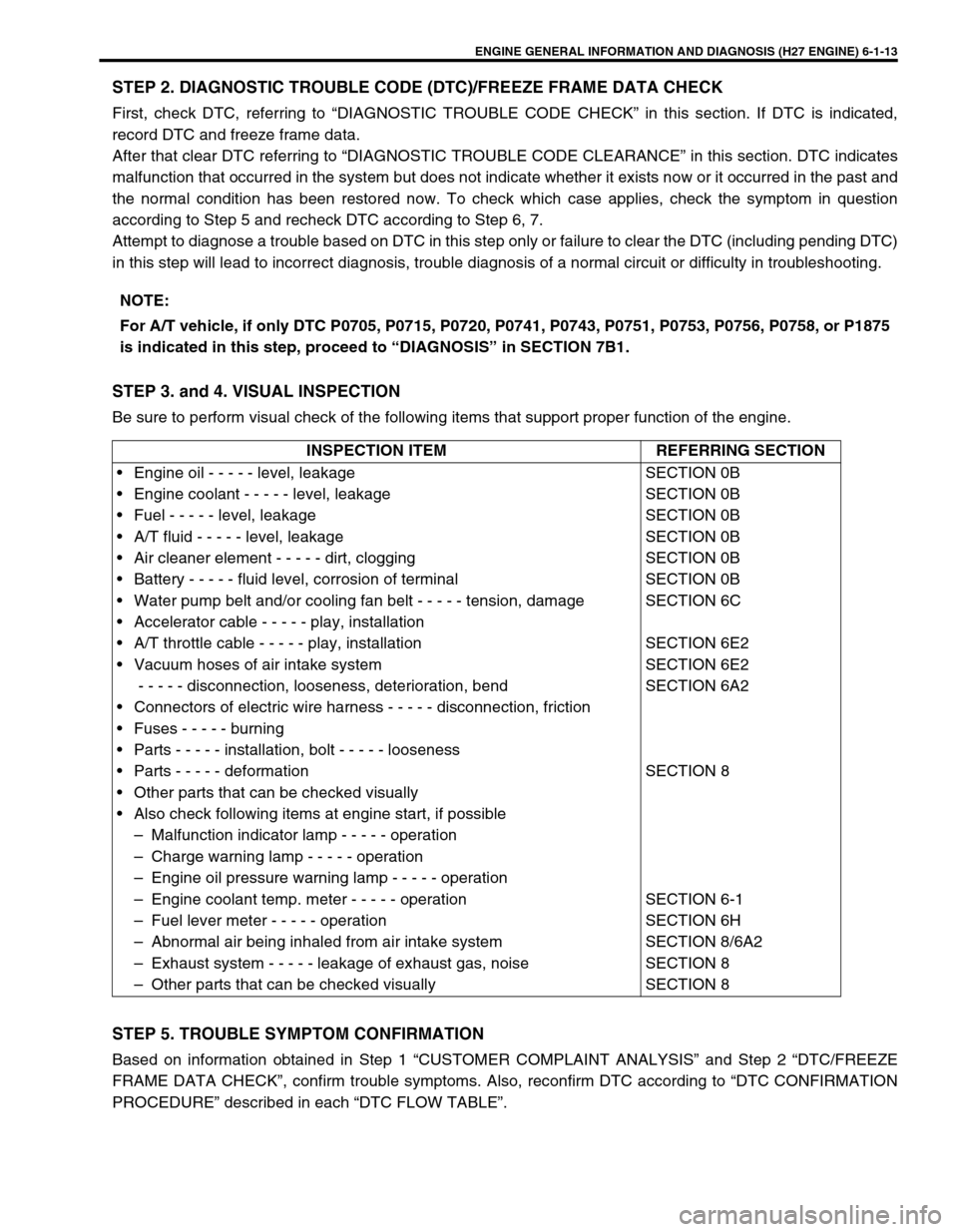
STEP 3. and 4. VISUAL INSPECTION
Be sure to perform visual check of the following items that support proper function of the engine.
STEP 5. TROUBLE SYMPTOM CONFIRMATION
Based on information obtained in Step 1 “CUSTOMER COMPLAINT ANALYSIS” and Step 2 “DTC/FREEZE
FRAME DATA CHECK”, confirm trouble symptoms. Also, reconfirm DTC according to “DTC CONFIRMATION
PROCEDURE” described in each “DTC FLOW TABLE”.NOTE:
For A/T vehicle, if only DTC P0705, P0715, P0720, P0741, P0743, P0751, P0753, P0756, P0758, or P1875
is indicated in this step, proceed to “DIAGNOSIS” in SECTION 7B1.
INSPECTION ITEM REFERRING SECTION
• Engine oil - - - - - level, leakage
• Engine coolant - - - - - level, leakage
• Fuel - - - - - level, leakage
• A/T fluid - - - - - level, leakage
• Air cleaner element - - - - - dirt, clogging
• Battery - - - - - fluid level, corrosion of terminal
• Water pump belt and/or cooling fan belt - - - - - tension, damage
• Accelerator cable - - - - - play, installation
• A/T throttle cable - - - - - play, installation
• Vacuum hoses of air intake system
- - - - - disconnection, looseness, deterioration, bend
• Connectors of electric wire harness - - - - - disconnection, friction
• Fuses - - - - - burning
• Parts - - - - - installation, bolt - - - - - looseness
• Parts - - - - - deformation
• Other parts that can be checked visually
• Also check following items at engine start, if possible
– Malfunction indicator lamp - - - - - operation
– Charge warning lamp - - - - - operation
– Engine oil pressure warning lamp - - - - - operation
– Engine coolant temp. meter - - - - - operation
– Fuel lever meter - - - - - operation
– Abnormal air being inhaled from air intake system
– Exhaust system - - - - - leakage of exhaust gas, noise
– Other parts that can be checked visuallySECTION 0B
SECTION 0B
SECTION 0B
SECTION 0B
SECTION 0B
SECTION 0B
SECTION 6C
SECTION 6E2
SECTION 6E2
SECTION 6A2
SECTION 8
SECTION 6-1
SECTION 6H
SECTION 8/6A2
SECTION 8
SECTION 8
Page 291 of 656

6A2-4 ENGINE MECHANICAL (H27 ENGINE)
8) Disconnect accelerator cable (1) and A/T throttle cable (2)
(for A/T vehicle) from throttle body.
9) Disconnect water hoses (3) from throttle body.
10) Disconnect injector wire (1) coupler.
11) Disconnect brake booster hose (2) from intake manifold.
12) Disconnect couplers of TP sensor (1) and IAC valve (2).
13) Disconnect earth terminal (3) from intake collector.
14) Remove clamp bracket (4) from intake collector.
15) Disconnect couplers from manifold absolute pressure (MAP)
sensor, EVAP canister purge valve, earth terminal and EGR
valve.
16) Disconnect PCV hose from cylinder head cover.
Disconnect breather hoses from throttle body or cylinder
head cover.
17) Disconnect hoses of EVAP canister purge valve and heater.
18) Remove EGR pipe.
12
33
2
1
2
14
3
1. EVAP canister purge valve 6. PCV hose
2. EGR valve 7. Water hose
3. EGR pipe 8. Breather hose
4. EVAP canister purge valve hose 9. Earth terminal coupler
5. Heater hose
9
4
1 7
6
2
35
8
Page 295 of 656

6A2-8 ENGINE MECHANICAL (H27 ENGINE)
16) Connect water hoses (3) to throttle body.
17) Connect accelerator cable (1) and A/T throttle cable (2) (for
A/T vehicle) to throttle body.
18) Install surge tank pipe (2) to intake manifold with new gas-
kets and intake air pipe (1) to throttle body.
19) Install surge tank cover (1).
20) Install air cleaner upper case.
21) Connect coupler to intake air temp. sensor and MAF sensor.
22) Install strut tower bar (1).
23) Check to ensure that all removed parts are back in place.
Reinstall any necessary parts which have not been rein-
stalled.
24) Refill cooling system referring to “COOLING SYSTEM
FLUSH AND REFILL” in Section 6B.
25) Connect negative cable at battery.
12
33
1
2
1
Page 307 of 656
6A2-20 ENGINE MECHANICAL (H27 ENGINE)
12) Install oil pan and oil pump strainer.
Refer to “OIL PAN AND OIL PUMP STRAINER” in this sec-
tion.
13) Install cylinder head cover.
Refer to “CYLINDER HEAD COVER” in this section.
14) Install exhaust manifold.
Refer to “EXHAUST MANIFOLD” in this section.
15) Install radiator outlet pipe, radiator, cooling fan and water
hose.
Refer to “COOLING WATER PIPES OR HOSES”, “RADIA-
TOR” and “COOLING FAN AND FAN CLUTCH” in Section
6B.
16) Install throttle body and intake manifold.
Refer to “THROTTLE BODY AND INTAKE MANIFOLD” in
this section.
17) Adjust water pump drive belt tension.
Refer to “COOLING FAN BELT TENSION CHECK AND
ADJUSTMENT” in Section 6B.
18) Adjust power steering pump drive belt tension.
Refer to “POWER STEERING PUMP DRIVE BELT” in Sec-
tion 3B1.
19) Adjust accelerator cable play and A/T throttle cable play.
Refer to “ACCELERATOR CABLE ADJUSTMENT” and “A/T
THROTTLE CABLE ADJUSTMENT (A/T VEHICLE)” in Sec-
tion 6E2.
20) Check to ensure that all removed parts are back in place.
Reinstall any necessary parts which have not been rein-
stalled.
21) Refill engine with engine oil, referring to “ENGINE OIL
CHANGE” in Section 0B.
22) Refill cooling system referring to “COOLING SYSTEM
FLUSH AND REFILL” in Section 6B.
23) Refill front differential housing with gear oil if drained, refer-
ring to “MAINTENANCE SERVICE” in Section 7E.
24) Connect negative cable at battery.
25) Check ignition timing and adjust as necessary, referring to
“IGNITION TIMING CHECK AND ADJUSTMENT” in Section
6F2.
26) Verify that there is no fuel leakage, water leakage, oil leak-
age and exhaust gas leakage at each connection.
27) Check wheel alignment, referring to “STEERING ANGLE” in
Section 3A.
Page 313 of 656
6A2-26 ENGINE MECHANICAL (H27 ENGINE)
Unit Repair Overhaul
Engine Assembly
REMOVAL
1) Release fuel pressure in fuel feed line. Refer to “FUEL
PRESSURE RELIEF PROCEDURE” in Section 6.
2) Disconnect negative (–) cable at battery.
3) Remove engine hood.
4) Drain engine oil.
5) Drain coolant.
6) Remove radiator, radiator fan shroud, cooling fan and radia-
tor reservoir. Refer to “COOLING FAN AND FAN CLUTCH”
and “RADIATOR” in Section 6B.
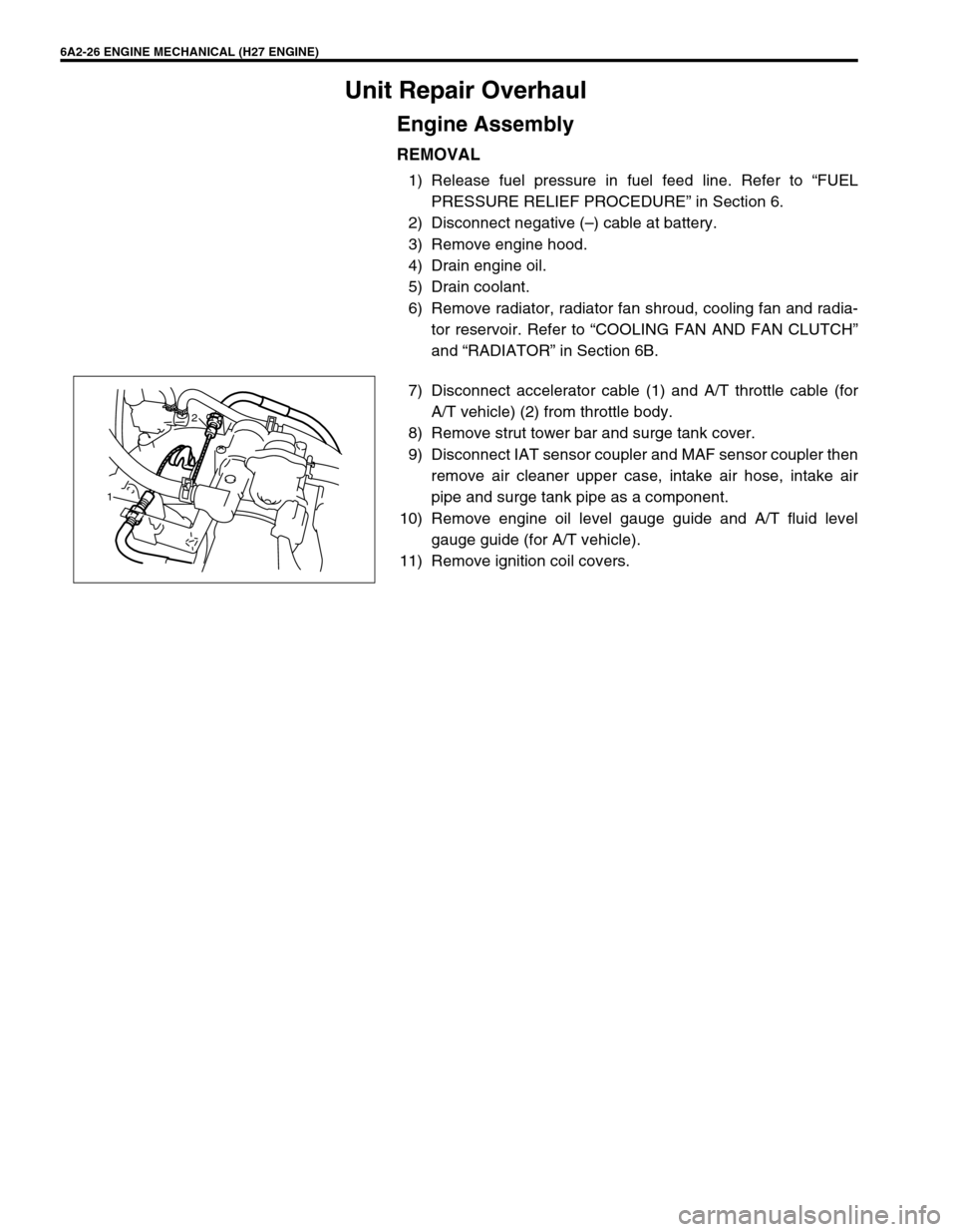
7) Disconnect accelerator cable (1) and A/T throttle cable (for
A/T vehicle) (2) from throttle body.
8) Remove strut tower bar and surge tank cover.
9) Disconnect IAT sensor coupler and MAF sensor coupler then
remove air cleaner upper case, intake air hose, intake air
pipe and surge tank pipe as a component.
10) Remove engine oil level gauge guide and A/T fluid level
gauge guide (for A/T vehicle).
11) Remove ignition coil covers.
12
Page 316 of 656
ENGINE MECHANICAL (H27 ENGINE) 6A2-29
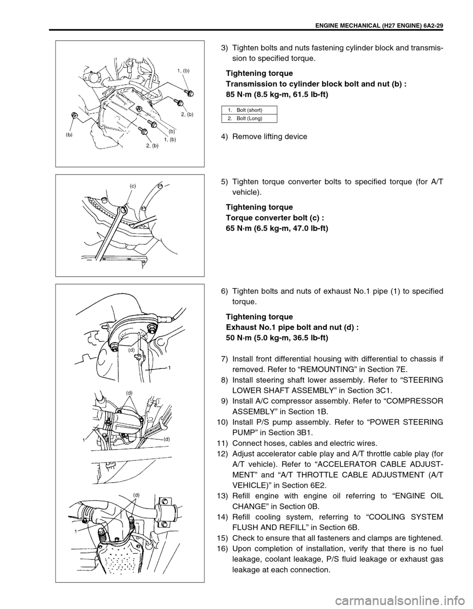
3) Tighten bolts and nuts fastening cylinder block and transmis-
sion to specified torque.
Tightening torque
Transmission to cylinder block bolt and nut (b) :
85 N·m (8.5 kg-m, 61.5 lb-ft)
4) Remove lifting device
5) Tighten torque converter bolts to specified torque (for A/T
vehicle).
Tightening torque
Torque converter bolt (c) :
65 N·m (6.5 kg-m, 47.0 lb-ft)
6) Tighten bolts and nuts of exhaust No.1 pipe (1) to specified
torque.
Tightening torque
Exhaust No.1 pipe bolt and nut (d) :
50 N·m (5.0 kg-m, 36.5 lb-ft)
7) Install front differential housing with differential to chassis if
removed. Refer to “REMOUNTING” in Section 7E.
8) Install steering shaft lower assembly. Refer to “STEERING
LOWER SHAFT ASSEMBLY” in Section 3C1.
9) Install A/C compressor assembly. Refer to “COMPRESSOR
ASSEMBLY” in Section 1B.
10) Install P/S pump assembly. Refer to “POWER STEERING
PUMP” in Section 3B1.
11) Connect hoses, cables and electric wires.
12) Adjust accelerator cable play and A/T throttle cable play (for
A/T vehicle). Refer to “ACCELERATOR CABLE ADJUST-
MENT” and “A/T THROTTLE CABLE ADJUSTMENT (A/T
VEHICLE)” in Section 6E2.
13) Refill engine with engine oil referring to “ENGINE OIL
CHANGE” in Section 0B.
14) Refill cooling system, referring to “COOLING SYSTEM
FLUSH AND REFILL” in Section 6B.
15) Check to ensure that all fasteners and clamps are tightened.
16) Upon completion of installation, verify that there is no fuel
leakage, coolant leakage, P/S fluid leakage or exhaust gas
leakage at each connection.
1. Bolt (short)
2. Bolt (Long)
Page 334 of 656

ENGINE AND EMISSION CONTROL SYSTEM (SEQUENTIAL MULTIPORT FUEL INJECTION FOR H27 ENGINE) 6E2-1
6E2
SECTION 6E2
ENGINE AND EMISSION CONTROL SYSTEM
(SEQUENTIAL MULTIPORT FUEL INJECTION
FOR H27 ENGINE)
CONTENTS
General Description ..................................... 6E2-2
System Flow ............................................... 6E2-3
System Diagram ......................................... 6E2-4
Air Intake System ....................................... 6E2-6
Fuel Delivery System ................................. 6E2-7
Electronic Control System .......................... 6E2-8
Engine and Emission Control Input/Output
Table ........................................................ 6E2-12
Diagnosis .................................................... 6E2-12
On-Vehicle Service..................................... 6E2-13
General .................................................... 6E2-13
Accelerator Cable Adjustment .................. 6E2-14
A/T Throttle Cable Adjustment
(A/T Vehicle) ............................................ 6E2-14Idle Speed/Idle Air Control (IAC) Duty
Inspection................................................. 6E2-15
[Using SUZUKI scan tool] .................... 6E2-15
[Not using SUZUKI scan tool]
(vehicle with monitor connector) .......... 6E2-16
Idle mixture inspection/adjustment
(vehicle without heated oxygen sensor) 6E2-17
Air Intake System ..................................... 6E2-18
Throttle body ........................................ 6E2-18
Idle air control valve (IAC valve) .......... 6E2-21
Fast idle air valve ................................. 6E2-22
Fuel Delivery System ............................... 6E2-23
Fuel pressure inspection ...................... 6E2-23
Fuel pump ............................................ 6E2-24
Fuel pressure regulator ........................ 6E2-25 WARNING:
For vehicles equipped with Supplemental Restraint (Air Bag) System:
Service on and around the air bag system components or wiring must be performed only by an
authorized SUZUKI dealer. Refer to “Air Bag System Components and Wiring Location View” under
“General Description” in air bag system section in order to confirm whether you are performing ser-
vice on or near the air bag system components or wiring. Please observe all WARNINGS and “Ser-
vice Precautions” under “On-Vehicle Service” in air bag system section before performing service
on or around the air bag system components or wiring. Failure to follow WARNINGS could result in
unintentional activation of the system or could render the system inoperative. Either of these two
conditions may result in severe injury.
Technical service work must be started at least 90 seconds after the ignition switch is turned to the
“LOCK” position and the negative cable is disconnected from the battery. Otherwise, the system
may be activated by reserve energy in the Sensing and Diagnostic Module (SDM).
NOTE:
Whether following systems (parts) are used in the particular vehicle or not depends on specifications.
Be sure to bear this in mind when performing service work.
Monitor connector
CKP sensor
MAP sensor
EGR valve
Heated oxygen sensor or CO adjusting resistor
Three way catalytic converter, Warm-up three way catalytic converter
Page 347 of 656
6E2-14 ENGINE AND EMISSION CONTROL SYSTEM (SEQUENTIAL MULTIPORT FUEL INJECTION FOR H27 ENGINE)
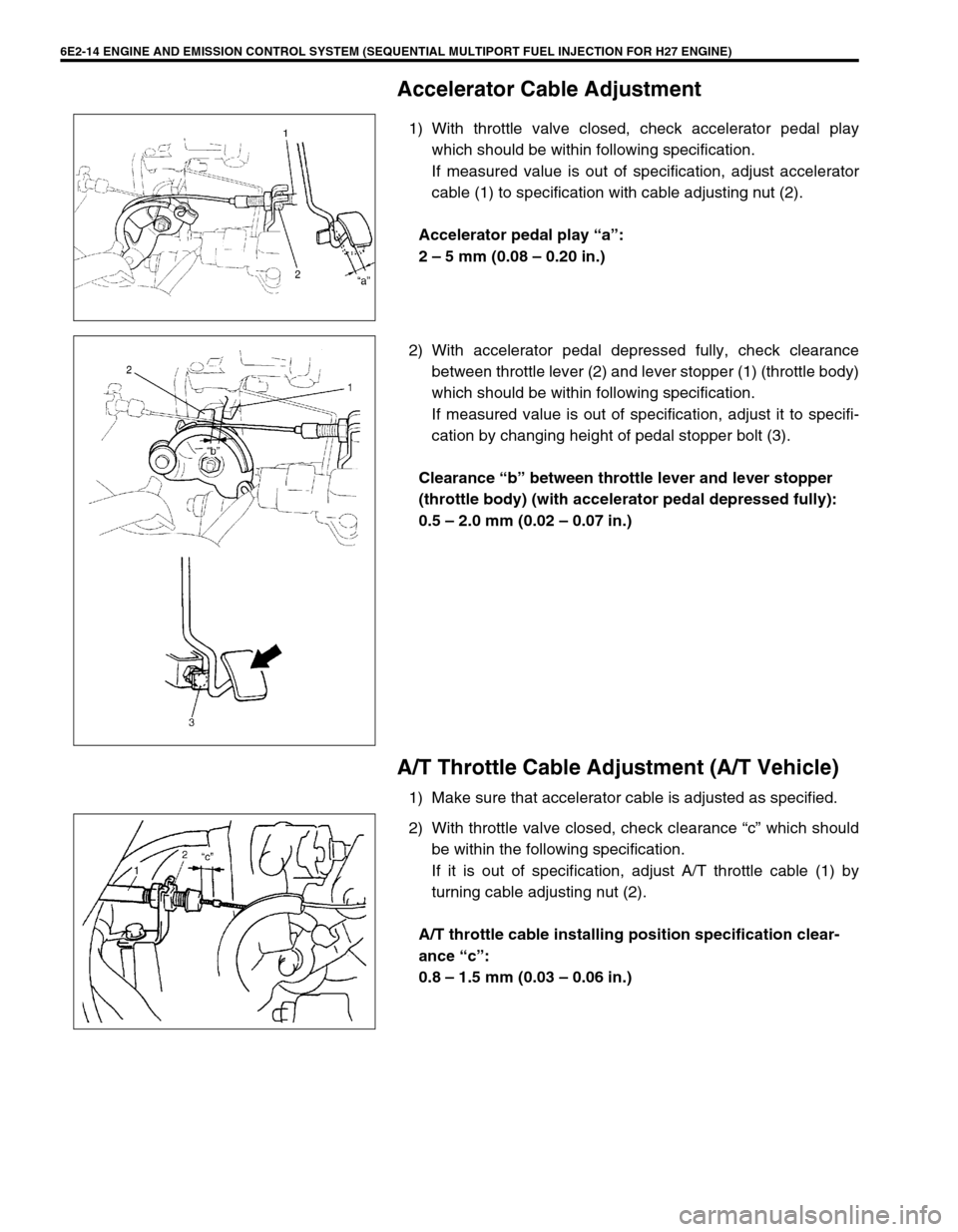
Accelerator Cable Adjustment
1) With throttle valve closed, check accelerator pedal play
which should be within following specification.
If measured value is out of specification, adjust accelerator
cable (1) to specification with cable adjusting nut (2).
Accelerator pedal play “a”:
2 – 5 mm (0.08 – 0.20 in.)
2) With accelerator pedal depressed fully, check clearance
between throttle lever (2) and lever stopper (1) (throttle body)
which should be within following specification.
If measured value is out of specification, adjust it to specifi-
cation by changing height of pedal stopper bolt (3).
Clearance “b” between throttle lever and lever stopper
(throttle body) (with accelerator pedal depressed fully):
0.5 – 2.0 mm (0.02 – 0.07 in.)
A/T Throttle Cable Adjustment (A/T Vehicle)
1) Make sure that accelerator cable is adjusted as specified.
2) With throttle valve closed, check clearance “c” which should
be within the following specification.
If it is out of specification, adjust A/T throttle cable (1) by
turning cable adjusting nut (2).
A/T throttle cable installing position specification clear-
ance “c”:
0.8 – 1.5 mm (0.03 – 0.06 in.)