1999 SUZUKI GRAND VITARA ACCELERATOR CABLE
[x] Cancel search: ACCELERATOR CABLEPage 348 of 656
ENGINE AND EMISSION CONTROL SYSTEM (SEQUENTIAL MULTIPORT FUEL INJECTION FOR H27 ENGINE) 6E2-15
Idle Speed/Idle Air Control (IAC) Duty Inspec-
tion
Before idle speed/IAC duty check, make sure of the following.
•Lead wires and hoses of engine/emission control systems
are connected securely.
•Accelerator cable is adjusted.
•Ignition timing is within specification.
•All accessories (wipers, heater, lights, A/C, etc.) are out of
service.
•Air cleaner has been properly installed and is in good condi-
tion.
•ECM (PCM) does not detect any malfunction DTC.
After above items are all confirmed, check idle speed and IAC
duty as follows.
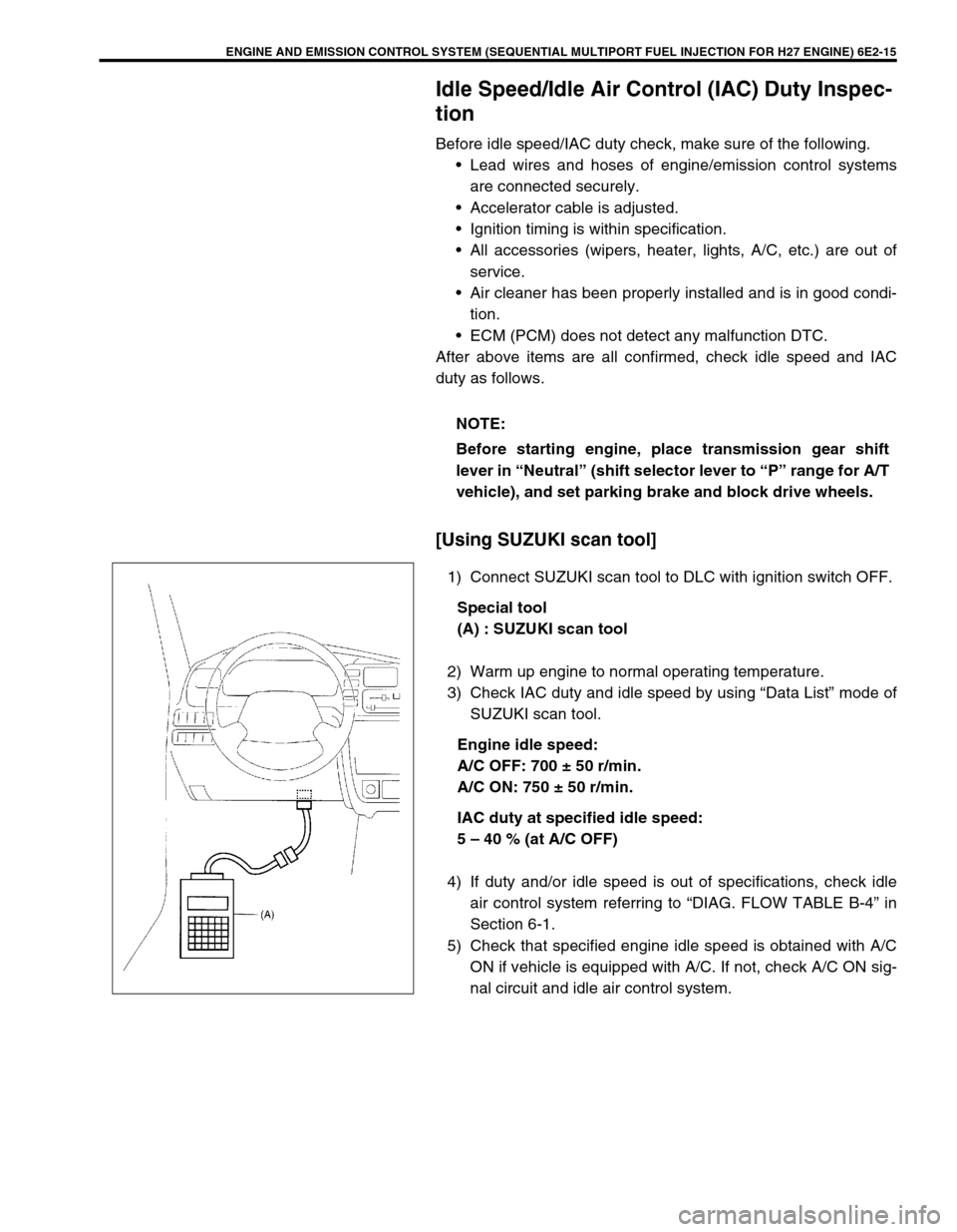
[Using SUZUKI scan tool]
1) Connect SUZUKI scan tool to DLC with ignition switch OFF.
Special tool
(A) : SUZUKI scan tool
2) Warm up engine to normal operating temperature.
3) Check IAC duty and idle speed by using “Data List” mode of
SUZUKI scan tool.
Engine idle speed:
A/C OFF: 700 ± 50 r/min.
A/C ON: 750 ± 50 r/min.
IAC duty at specified idle speed:
5 – 40 % (at A/C OFF)
4) If duty and/or idle speed is out of specifications, check idle
air control system referring to “DIAG. FLOW TABLE B-4” in
Section 6-1.
5) Check that specified engine idle speed is obtained with A/C
ON if vehicle is equipped with A/C. If not, check A/C ON sig-
nal circuit and idle air control system. NOTE:
Before starting engine, place transmission gear shift
lever in “Neutral” (shift selector lever to “P” range for A/T
vehicle), and set parking brake and block drive wheels.
Page 351 of 656
6E2-18 ENGINE AND EMISSION CONTROL SYSTEM (SEQUENTIAL MULTIPORT FUEL INJECTION FOR H27 ENGINE)
Air Intake System
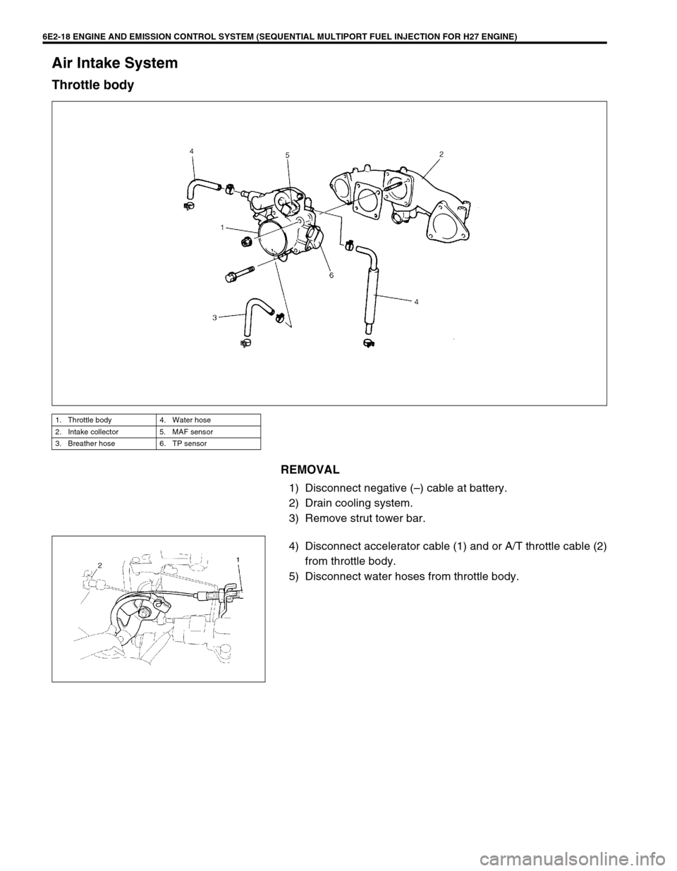
Throttle body
REMOVAL
1) Disconnect negative (–) cable at battery.
2) Drain cooling system.
3) Remove strut tower bar.
4) Disconnect accelerator cable (1) and or A/T throttle cable (2)
from throttle body.
5) Disconnect water hoses from throttle body.
1. Throttle body 4. Water hose
2. Intake collector 5. MAF sensor
3. Breather hose 6. TP sensor
Page 353 of 656

6E2-20 ENGINE AND EMISSION CONTROL SYSTEM (SEQUENTIAL MULTIPORT FUEL INJECTION FOR H27 ENGINE)
CLEANING
Clean throttle body bore and bypass air passages (1) by blowing
compressed air.
INSTALLATION
1) Clean mating surfaces and install throttle body gasket to
intake collector (1) with new gasket (2).
2) Install throttle body to intake collector and tighten bolts.
3) Connect PCV hose.
4) Install throttle body and intake collector to intake manifold
with new intake collector gaskets.
5) Install EGR pipe with new gaskets.
6) Connect breather hose and EVAP canister purge valve hose
and install PCV valve to cylinder head.
7) Connect connectors of EVAP canister purge valve, MAP
sensor and EGR valve.
Fix wire harness with clamps.
8) Install clamp bracket to intake collector.
9) Connect ground wire connector.
10) Connect connectors of TP sensor, ground and IAC valve.
11) Install surge tank pipe to intake manifold with new gaskets
and intake air pipe to throttle body. Install surge tank cover.
12) Connect engine coolant hoses to throttle body.
13) Connect accelerator cable and A/T throttle cable (A/T).CAUTION:
Do not blow compressed air through bypass air pas-
sage with IAC valve installed to throttle body. This will
cause IAC valve to malfunction.
TP sensor, idle air control valve or other components
containing rubber must not be places in a solvent or
cleaner bath.
A chemical reaction will cause these parts to swell,
harden or get distorted.
Page 354 of 656
ENGINE AND EMISSION CONTROL SYSTEM (SEQUENTIAL MULTIPORT FUEL INJECTION FOR H27 ENGINE) 6E2-21
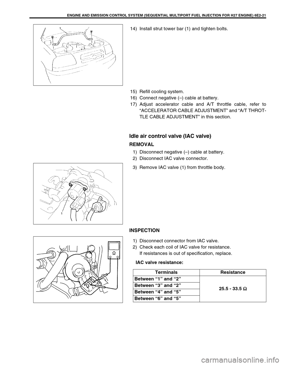
14) Install strut tower bar (1) and tighten bolts.
15) Refill cooling system.
16) Connect negative (–) cable at battery.
17) Adjust accelerator cable and A/T throttle cable, refer to
“ACCELERATOR CABLE ADJUSTMENT” and “A/T THROT-
TLE CABLE ADJUSTMENT” in this section.
Idle air control valve (IAC valve)
REMOVAL
1) Disconnect negative (–) cable at battery.
2) Disconnect IAC valve connector.
3) Remove IAC valve (1) from throttle body.
INSPECTION
1) Disconnect connector from IAC valve.
2) Check each coil of IAC valve for resistance.
If resistances is out of specification, replace.
IAC valve resistance:
Terminals Resistance
Between “1” and “2”
25.5 - 33.5 Ω
ΩΩ Ω Between “3” and “2”
Between “4” and “5”
Between “6” and “5”
Page 377 of 656
6E2-44 ENGINE AND EMISSION CONTROL SYSTEM (SEQUENTIAL MULTIPORT FUEL INJECTION FOR H27 ENGINE)
Emission Control System
EGR system (if equipped)
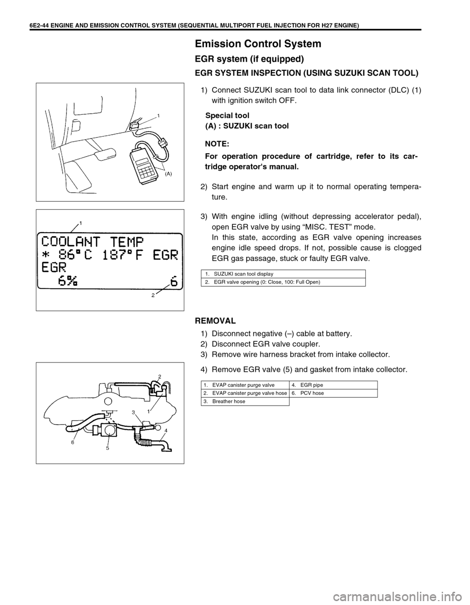
EGR SYSTEM INSPECTION (USING SUZUKI SCAN TOOL)
1) Connect SUZUKI scan tool to data link connector (DLC) (1)
with ignition switch OFF.
Special tool
(A) : SUZUKI scan tool
2) Start engine and warm up it to normal operating tempera-
ture.
3) With engine idling (without depressing accelerator pedal),
open EGR valve by using “MISC. TEST” mode.
In this state, according as EGR valve opening increases
engine idle speed drops. If not, possible cause is clogged
EGR gas passage, stuck or faulty EGR valve.
REMOVAL
1) Disconnect negative (–) cable at battery.
2) Disconnect EGR valve coupler.
3) Remove wire harness bracket from intake collector.
4) Remove EGR valve (5) and gasket from intake collector.NOTE:
For operation procedure of cartridge, refer to its car-
tridge operator's manual.
1. SUZUKI scan tool display
2. EGR valve opening (0: Close, 100: Full Open)
1. EVAP canister purge valve 4. EGR pipe
2. EVAP canister purge valve hose 6. PCV hose
3. Breather hose
Page 423 of 656
7B1-14 AUTOMATIC TRANSMISSION (4 A/T)
Diagnostic Trouble Code Table
Refer to the same item in Section 6-1.
Fail Safe Table
Refer to the same item in Section 6-1.
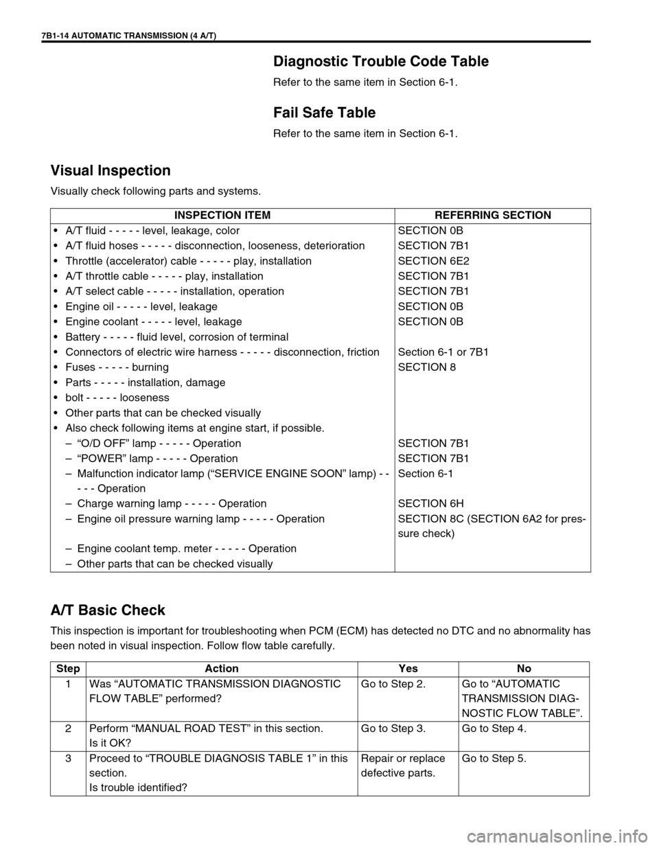
Visual Inspection
Visually check following parts and systems.
A/T Basic Check
This inspection is important for troubleshooting when PCM (ECM) has detected no DTC and no abnormality has
been noted in visual inspection. Follow flow table carefully.INSPECTION ITEM REFERRING SECTION
•A/T fluid - - - - - level, leakage, color SECTION 0B
•A/T fluid hoses - - - - - disconnection, looseness, deterioration SECTION 7B1
•Throttle (accelerator) cable - - - - - play, installation SECTION 6E2
•A/T throttle cable - - - - - play, installation SECTION 7B1
•A/T select cable - - - - - installation, operation SECTION 7B1
•Engine oil - - - - - level, leakage SECTION 0B
•Engine coolant - - - - - level, leakage SECTION 0B
•Battery - - - - - fluid level, corrosion of terminal
•Connectors of electric wire harness - - - - - disconnection, friction Section 6-1 or 7B1
•Fuses - - - - - burning SECTION 8
•Parts - - - - - installation, damage
•bolt - - - - - looseness
•Other parts that can be checked visually
•Also check following items at engine start, if possible.
–“O/D OFF” lamp - - - - - Operation SECTION 7B1
–“POWER” lamp - - - - - Operation SECTION 7B1
–Malfunction indicator lamp (“SERVICE ENGINE SOON” lamp) - -
- - - OperationSection 6-1
–Charge warning lamp - - - - - Operation SECTION 6H
–Engine oil pressure warning lamp - - - - - Operation SECTION 8C (SECTION 6A2 for pres-
sure check)
–Engine coolant temp. meter - - - - - Operation
–Other parts that can be checked visually
Step Action Yes No
1Was “AUTOMATIC TRANSMISSION DIAGNOSTIC
FLOW TABLE” performed?Go to Step 2. Go to “AUTOMATIC
TRANSMISSION DIAG-
NOSTIC FLOW TABLE”.
2Perform “MANUAL ROAD TEST” in this section.
Is it OK?Go to Step 3. Go to Step 4.
3Proceed to “TROUBLE DIAGNOSIS TABLE 1” in this
section.
Is trouble identified?Repair or replace
defective parts.Go to Step 5.
Page 436 of 656

AUTOMATIC TRANSMISSION (4 A/T) 7B1-27
DTC CONFIRMATION PROCEDURE
1) Connect scan tool to DLC with ignition switch OFF, if available.
2) Clear DTC, pending DTC and freeze frame data in PCM memory by using scan tool and start engine.
3) Shift A/T selector lever to each of L, 2, D, N, R and P ranges for 30 seconds each.
4) Increase vehicle speed to about 70 km/h (45 mile/h) in D range.
5) Keep driving above vehicle speed for 30 seconds.
6) Release accelerator pedal, decrease vehicle speed and stop vehicle.
7) Check DTC and/or pending DTC.
TROUBLESHOOTING
WARNING:
When performing a road test, select a place where there is no traffic or possibility of a traffic acci-
dent and be very careful during testing to avoid occurrence of an accident.
Road test should be carried out with 2 persons, a driver and a tester, on a level road.
Step Action Yes No
1Was “A/T DIAGNOSTIC FLOW TABLE” in this section
performed?Go to Step 2. Go to “A/T DIAGNOS-
TIC FLOW TABLE” in
this section.
2 Do you have SUZUKI scan tool? Go to Step 3. Go to Step 4.
3 Check Transmission range switch (sensor) circuit for
operation.
Check by using SUZUKI scan tool :
1) Connect SUZUKI scan tool to DLC with ignition
switch OFF.
2) Turn ignition switch ON and check transmission
range signal (P, R, N, D, 2 or L) on display when
shifting select lever to each range.
Is applicable range indicated?
Are check results satisfactory?Intermittent trouble.
Check for intermittent
referring to “INTER-
MITTENT AND POOR
CONNECTION” in
Section 0A.Go to Step 5.
4 Check Transmission range switch (sensor) circuit for
operation.
Check by not using SUZUKI scan tool :
1) Turn ignition switch ON.
2) Check voltage at terminals C51-1-6, C51-1-7,
C51-1-18, C51-1-19, C51-1-27 and C51-1-28
respectively with select lever shifted to each
range.
Taking terminal C51-1-28 as an example, is battery
voltage indicated only when select lever is shifted to
“2” range and 0 V for other ranges as shown in figure?
Check voltage at other terminals likewise, referring to
figure.
Are check results satisfactory?Intermittent trouble.
Check for intermittent
referring to “INTER-
MITTENT AND POOR
CONNECTION” in
Section 0A.Go to Step 5.
5 Check select cable for adjustment referring to
“SELECT CABLE ADJUSTMENT” in this section.
Is it adjusted correctly?Go to Step 6. Adjust.
Page 449 of 656
7B1-40 AUTOMATIC TRANSMISSION (4 A/T)
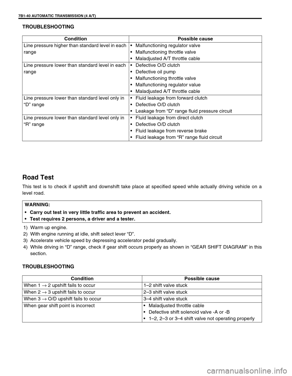
TROUBLESHOOTING
Road Test
This test is to check if upshift and downshift take place at specified speed while actually driving vehicle on a
level road.
1) Warm up engine.
2) With engine running at idle, shift select lever “D”.
3) Accelerate vehicle speed by depressing accelerator pedal gradually.
4) While driving in “D” range, check if gear shift occurs properly as shown in “GEAR SHIFT DIAGRAM” in this
section.
TROUBLESHOOTING
Condition Possible cause
Line pressure higher than standard level in each
range•Malfunctioning regulator valve
•Malfunctioning throttle valve
•Maladjusted A/T throttle cable
Line pressure lower than standard level in each
range•Defective O/D clutch
•Defective oil pump
•Malfunctioning throttle valve
•Malfunctioning regulator value
•Maladjusted A/T throttle cable
Line pressure lower than standard level only in
“D” range•Fluid leakage from forward clutch
•Defective O/D clutch
•Leakage from “D” range fluid pressure circuit
Line pressure lower than standard level only in
“R” range•Fluid leakage from direct clutch
•Defective O/D clutch
•Fluid leakage from reverse brake
•Fluid leakage from “R” range fluid circuit
WARNING:
Carry out test in very little traffic area to prevent an accident.
Test requires 2 persons, a driver and a tester.
Condition Possible cause
When 1 → 2 upshift fails to occur 1–2 shift valve stuck
When 2 → 3 upshift fails to occur 2–3 shift valve stuck
When 3 → O/D upshift fails to occur 3–4 shift valve stuck
When gear shift point is incorrect•Maladjusted throttle cable
•Defective shift solenoid valve -A or -B
•1–2, 2–3 or 3–4 shift valve not operating properly