Page 381 of 656
6E2-48 ENGINE AND EMISSION CONTROL SYSTEM (SEQUENTIAL MULTIPORT FUEL INJECTION FOR H27 ENGINE)
PCV system
PCV HOSE
Check hoses for connection, leakage, clog, and deterioration.
Replace as necessary.
Tightening Torque Specification
Special Tool
NOTE:
Be sure to check that there is no obstruction in PCV
valve or its hoses (6) before checking engine idle speed/
IAC duty for obstructed PCV valve or hose hampers its
accurate checking.
1. EVAP canister purge valve 4. EGR pipe
2. EVAP canister purge valve hose 5. EGR valve
3. Breather hose 6. PCV hose
Fastening partTightening torque
Nm kg-m lb-ft
Heated oxygen sensor 45 4.5 32.5
Fuel pressure regulator bolts 10 1.0 7.5
Fuel pipe union bolts 30 3.0 22.0
Engine coolant temp. sensor 15 1.5 11.0
09912-58441 09912-58431 09912-58490 09912-58421
Pressure gauge Pressure hose 3-way joint & hose Checking tool set
(See NOTE “A”.)
Page 399 of 656
6H-2 CHARGING SYSTEM
General Description
Generator
WIRING CIRCUIT
B : Generator output (Battery terminal) L : Lamp terminal 5. Stator core 10. Rear end frame
D : Dummy terminal 1. Pulley 6. Field coil 11. Drive end frame
E : Ground 2. Pulley nut 7. Rectifier
F : Field coil terminal 3. Rotor fan 8. Brush
IG : Ignition terminal 4. Stator coil 9. Regulator
1. Generator with regulator assembly 3. Stator coil 5. Field coil (rotor coil) 7. Main switch
2. I.C. regulator 4. Diode 6. Charge indicator light 8. Battery
Page 400 of 656
CHARGING SYSTEM 6H-3
Unit Repair Overhaul
Generator Assembly
Inspection
Rotor
•Using ohmmeter, check for continuity between slip rings of
rotor. If there is no continuity, replace rotor.
Standard resistance between slip rings of rotor
: 1.6 – 2.0 Ω
ΩΩ Ω at 20°C (68°F)
1. Pulley nut 6. Driver end bearing 11. Wave washer 16. Regulator 21. Terminal plate
2. Pulley 7. Bearing retainer 12. Rear end frame 17. Brush
3. Drive end bearing 8. Rotor 13. Seal plate 18. Brush holder
4. Stator 9. End housing bearing 14. Rectifier 19. Brush holder cover
5. Stud bolt 10. Bearing cover 15. Insulator 20. Rear end cover
Page 403 of 656

6H-6 CHARGING SYSTEM
Specifications
Battery
Generator
Tightening Torque Specification
Battery type 55D23L 75D23L 95D26L
Rated capacity AH/5HR, 12 Volts 48 52 66
Electrolyte L (US/Imp.pt) 3.9 (8.24/6.86) 3.9 (8.24/6.86) 4.0 (8.53/7.04)
Electrolyte S.G. 1.28 when fully charged at 20°C (68°F)
Type 105 A type
Rated voltage 12 V
Nominal output 105 A
Permissible max. speed 18000 r/min.
No-load speed 1150 r/min (rpm)
Setting voltage 14.2 to 14.8 V
Permissible ambient temperature–30 to 90 °C (–22 to 194 °F)
Polarity Negative ground
Rotation Clockwise viewed from pulley side
Fastening partTightening torque
Nm kg-m lb-ft
Body ground bolt 8 0.8 6.0
Generator mounting bolts and nut 23 2.3 16.5
“B” terminal inner nut 3.6 0.37 3.0
“B” terminal outer nut 8 0.8 6.0
Generator pulley nut 111 11.2 81.5
Rear end frame nuts 4.5 0.45 3.5
Rear end cover nuts 4.5 0.45 3.5
Stator stud bolts 9.8 1.0 7.0
Drive end bearing plate screws 3.0 0.30 2.2
Rectifier screws 3.0 0.30 2.2
Regulator and brush holder screws 2.0 0.20 1.5
Terminal plate bolt 3.9 0.39 3.0
Page 424 of 656

AUTOMATIC TRANSMISSION (4 A/T) 7B1-15
Trouble Diagnosis Table 1
Trouble Diagnosis Table 2
TRANSMISSION FLUID
RUNNING CONDITION
4 Perform stall test, time rag test, line pressure test,
engine brake test and “P” range test referring to
“STALL TEST”, “LINE PRESSURE TEST”, “ENGINE
BRAKE TEST” and ““P” RANGE TEST” in this section.
Are the test results satisfactory?Go to Step 5. Proceed to “TROUBLE
DIAGNOSIS TABLE 3” in
this section.
5 Proceed to “TROUBLE DIAGNOSIS TABLE 2” in this
section.
Is trouble identified?Repair or replace
defective parts.Proceed to “TROUBLE
DIAGNOSIS TABLE 3” in
this section. Step Action Yes No
Condition Possible Cause Correction
TCC does not operateBrake pedal (stop lamp) switch or its circuit
faulty (H25 engine only)Refer to “DIAGNOSTIC FLOW
TABLE A-1” in this section.
4WD low switch or its circuit faulty
Engine coolant temp. sensor or its circuit faulty
Cruise control signal circuit faulty (if equipped)
Gear does not change
to 4thO/D off switch or its circuit faulty Refer to “DIAGNOSTIC FLOW
TABLE A-2” in this section.
4WD low switch or its circuit faulty
Engine coolant temp. sensor or its circuit faulty
Cruise control signal circuit faulty (if equipped)
Condition Possible Cause Correction
Low fluid pressureClogged oil pump strainer Wash strainer.
Malfunction of pressure regulator valve Overhaul valve body.
High fluid pressurePressure regulator valve Overhaul valve body.
Condition Possible Cause Correction
Unable to run in all
rangeRegulator valve stick Replace.
Clogged oil strainer Wash strainer.
Seized or broken planetary gear Repair or replace.
Faulty manual valve Replace.
Poor 1st speed run-
ning or excessive slip-
page in “D” or “2”Faulty 1–2 shift valve Replace.
Page 425 of 656

7B1-16 AUTOMATIC TRANSMISSION (4 A/T)
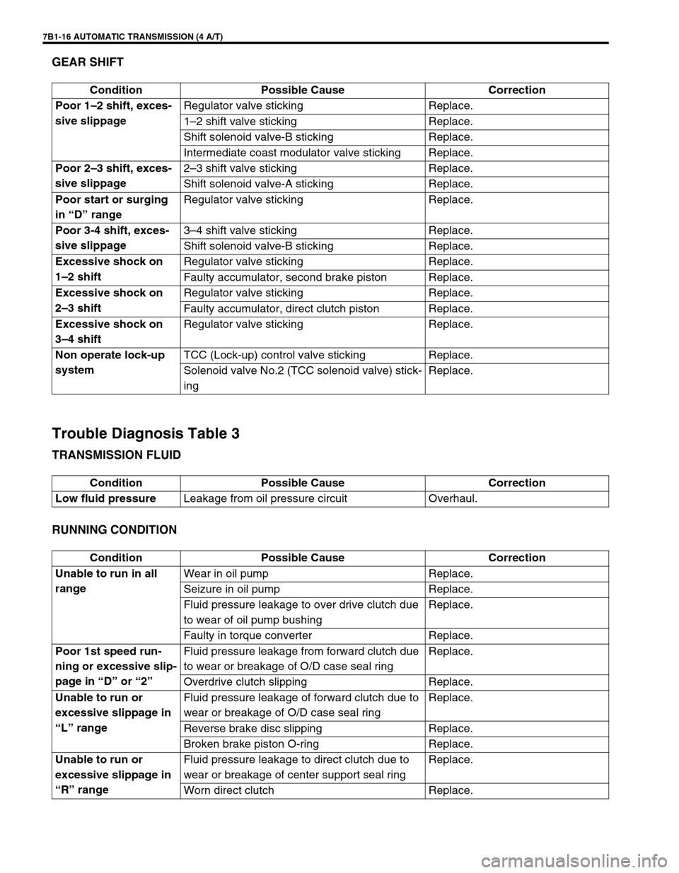
GEAR SHIFT
Trouble Diagnosis Table 3
TRANSMISSION FLUID
RUNNING CONDITION
Condition Possible Cause Correction
Poor 1–2 shift, exces-
sive slippageRegulator valve sticking Replace.
1–2 shift valve sticking Replace.
Shift solenoid valve-B sticking Replace.
Intermediate coast modulator valve sticking Replace.
Poor 2–3 shift, exces-
sive slippage2–3 shift valve sticking Replace.
Shift solenoid valve-A sticking Replace.
Poor start or surging
in “D” rangeRegulator valve sticking Replace.
Poor 3-4 shift, exces-
sive slippage3–4 shift valve sticking Replace.
Shift solenoid valve-B sticking Replace.
Excessive shock on
1–2 shiftRegulator valve sticking Replace.
Faulty accumulator, second brake piston Replace.
Excessive shock on
2–3 shiftRegulator valve sticking Replace.
Faulty accumulator, direct clutch piston Replace.
Excessive shock on
3–4 shiftRegulator valve sticking Replace.
Non operate lock-up
systemTCC (Lock-up) control valve sticking Replace.
Solenoid valve No.2 (TCC solenoid valve) stick-
ingReplace.
Condition Possible Cause Correction
Low fluid pressureLeakage from oil pressure circuit Overhaul.
Condition Possible Cause Correction
Unable to run in all
rangeWear in oil pump Replace.
Seizure in oil pump Replace.
Fluid pressure leakage to over drive clutch due
to wear of oil pump bushingReplace.
Faulty in torque converter Replace.
Poor 1st speed run-
ning or excessive slip-
page in “D” or “2”Fluid pressure leakage from forward clutch due
to wear or breakage of O/D case seal ringReplace.
Overdrive clutch slipping Replace.
Unable to run or
excessive slippage in
“L” rangeFluid pressure leakage of forward clutch due to
wear or breakage of O/D case seal ringReplace.
Reverse brake disc slipping Replace.
Broken brake piston O-ring Replace.
Unable to run or
excessive slippage in
“R” rangeFluid pressure leakage to direct clutch due to
wear or breakage of center support seal ringReplace.
Worn direct clutch Replace.
Page 449 of 656

7B1-40 AUTOMATIC TRANSMISSION (4 A/T)
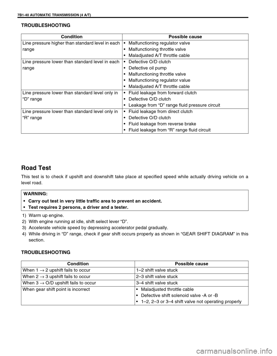
TROUBLESHOOTING
Road Test
This test is to check if upshift and downshift take place at specified speed while actually driving vehicle on a
level road.
1) Warm up engine.
2) With engine running at idle, shift select lever “D”.
3) Accelerate vehicle speed by depressing accelerator pedal gradually.
4) While driving in “D” range, check if gear shift occurs properly as shown in “GEAR SHIFT DIAGRAM” in this
section.
TROUBLESHOOTING
Condition Possible cause
Line pressure higher than standard level in each
range•Malfunctioning regulator valve
•Malfunctioning throttle valve
•Maladjusted A/T throttle cable
Line pressure lower than standard level in each
range•Defective O/D clutch
•Defective oil pump
•Malfunctioning throttle valve
•Malfunctioning regulator value
•Maladjusted A/T throttle cable
Line pressure lower than standard level only in
“D” range•Fluid leakage from forward clutch
•Defective O/D clutch
•Leakage from “D” range fluid pressure circuit
Line pressure lower than standard level only in
“R” range•Fluid leakage from direct clutch
•Defective O/D clutch
•Fluid leakage from reverse brake
•Fluid leakage from “R” range fluid circuit
WARNING:
Carry out test in very little traffic area to prevent an accident.
Test requires 2 persons, a driver and a tester.
Condition Possible cause
When 1 → 2 upshift fails to occur 1–2 shift valve stuck
When 2 → 3 upshift fails to occur 2–3 shift valve stuck
When 3 → O/D upshift fails to occur 3–4 shift valve stuck
When gear shift point is incorrect•Maladjusted throttle cable
•Defective shift solenoid valve -A or -B
•1–2, 2–3 or 3–4 shift valve not operating properly
Page 463 of 656

7B1-54 AUTOMATIC TRANSMISSION (4 A/T)
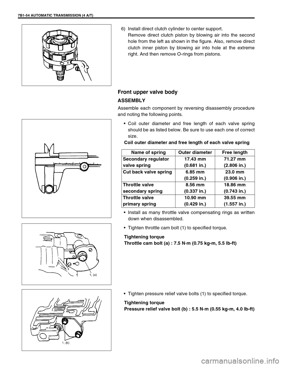
6) Install direct clutch cylinder to center support.
Remove direct clutch piston by blowing air into the second
hole from the left as shown in the figure. Also, remove direct
clutch inner piston by blowing air into hole at the extreme
right. And then remove O-rings from pistons.
Front upper valve body
ASSEMBLY
Assemble each component by reversing disassembly procedure
and noting the following points.
•Coil outer diameter and free length of each valve spring
should be as listed below. Be sure to use each one of correct
size.
Coil outer diameter and free length of each valve spring
•Install as many throttle valve compensating rings as written
down when disassembled.
•Tighten throttle cam bolt (1) to specified torque.
Tightening torque
Throttle cam bolt (a) : 7.5 N·m (0.75 kg-m, 5.5 lb-ft)
•Tighten pressure relief valve bolts (1) to specified torque.
Tightening torque
Pressure relief valve bolt (b) : 5.5 N·m (0.55 kg-m, 4.0 lb-ft)
Name of spring Outer diameter Free length
Secondary regulator
valve spring17.43 mm
(0.681 in.)71.27 mm
(2.806 in.)
Cut back valve spring 6.85 mm
(0.259 in.)23.0 mm
(0.906 in.)
Throttle valve
secondary spring8.56 mm
(0.337 in.)18.86 mm
(0.743 in.)
Throttle valve
primary spring10.90 mm
(0.429 in.)39.55 mm
(1.557 in.)