Page 464 of 656
AUTOMATIC TRANSMISSION (4 A/T) 7B1-55
LOWER VALVE BODY
1. Lower valve body 7. TCC (Lock-up) control valve plate 13. Primary regulator valve sleeve
2. Spring 8. TCC (Lock-up) control valve gasket 14. Primary regulator valve plunger
3. Pressure relief valve ball 9. TCC (Lock-up) control sleeve 15. Primary regulator valve
4. Pressure relief valve retainer 10. TCC (Lock-up) control valve 16. Spacer
5. Lower valve body plate 11. Pin
6. Lower valve body gasket 12. Retainer
Page 465 of 656
7B1-56 AUTOMATIC TRANSMISSION (4 A/T)
DISASSEMBLY
1) Remove bypass valve (1), bypass valve spring, check ball
valve damping spring, valve body ball (2) and ball valve
spring.
2) Remove lower valve body plate (1) and lower valve body
plate gasket.
3) Remove TCC (lock-up) control valve plate (2) and TCC
(lock-up) control valve gasket.
4) With pressure relief valve retainer (1) pressed with finger,
remove pressure relief valve bolt and then remove pressure
relief valve retainer (1), pressure relief valve spring and pres-
sure relief valve ball.
5) Remove TCC (lock-up) solenoid valve (1) and Then remove
O-ring (2) from TCC solenoid valve (1).
3. Check ball
4. Primary regulator valve sleeve retainer
5. Locating pin
Page 466 of 656
AUTOMATIC TRANSMISSION (4 A/T) 7B1-57
6) After removing shift solenoid valve (A & B) (1), remove sole-
noid valve gasket, low coast modulator valve spring (2), inter
coast modulator valve spring (3) and 2 intermediate coast
modulator valves (4).
7) Pressing TCC (lock-up) control sleeve with finger and using
magnet (1), remove locating pin and then remove TCC (lock-
up) control sleeve, TCC (lock-up) control valve and TCC
(lock-up) control valve spring.
8) Check which step of primary regulator valve sleeve (1) (how
many steps down from its tip) contacts primary regulator
valve sleeve retainer (2).
9) Pressing primary regulator valve sleeve (1) with finger and
using magnet, remove primary regulator valve sleeve
retainer and then remove primary regulator valve sleeve (1),
spacer (2), primary regulator valve plunger (3), primary regu-
lator valve spring (4) and primary regulator valve (5).
Page 467 of 656

7B1-58 AUTOMATIC TRANSMISSION (4 A/T)
ASSEMBLY
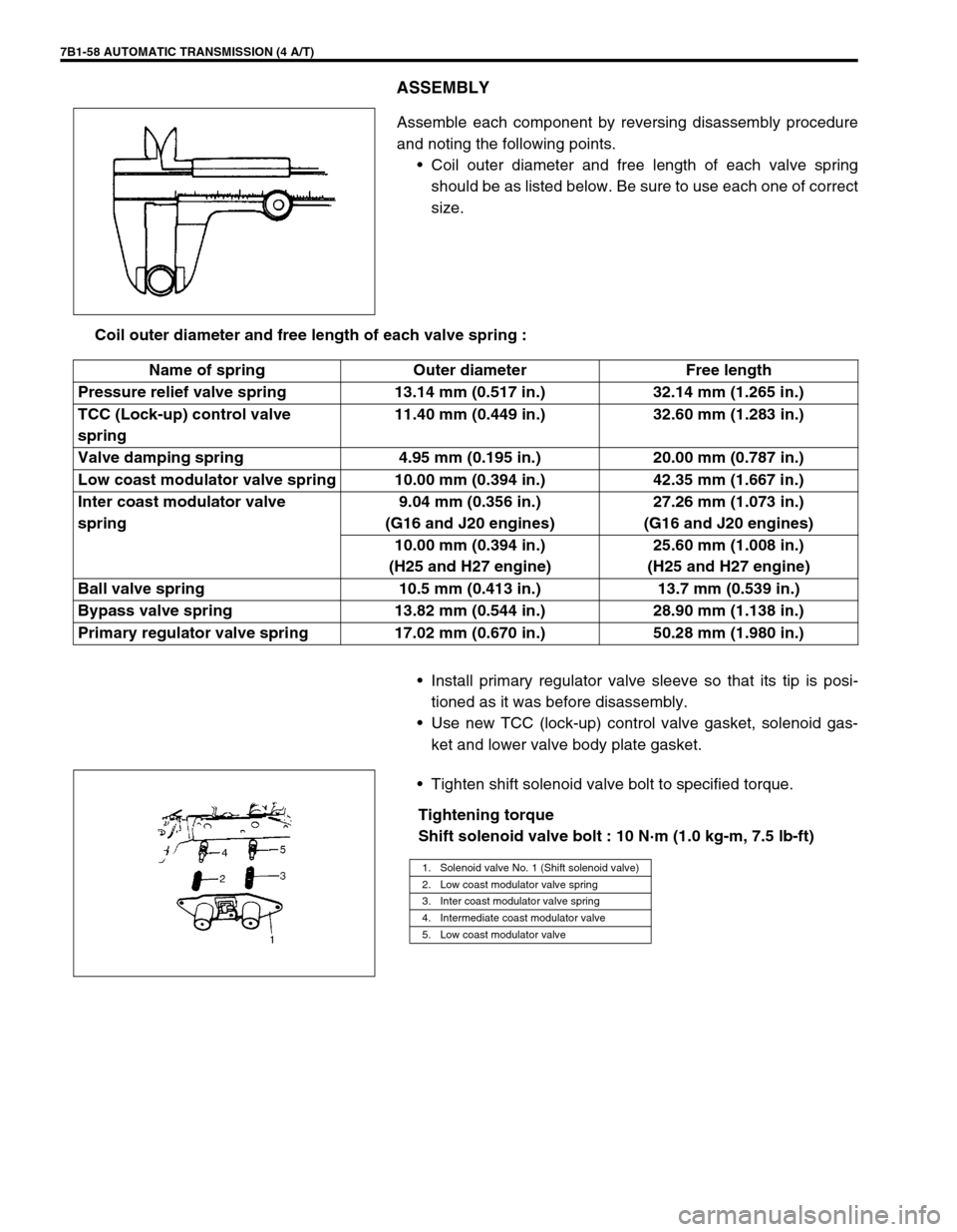
Assemble each component by reversing disassembly procedure
and noting the following points.
•Coil outer diameter and free length of each valve spring
should be as listed below. Be sure to use each one of correct
size.
Coil outer diameter and free length of each valve spring :
•Install primary regulator valve sleeve so that its tip is posi-
tioned as it was before disassembly.
•Use new TCC (lock-up) control valve gasket, solenoid gas-
ket and lower valve body plate gasket.
•Tighten shift solenoid valve bolt to specified torque.
Tightening torque
Shift solenoid valve bolt : 10 N·m (1.0 kg-m, 7.5 lb-ft)
Name of spring Outer diameter Free length
Pressure relief valve spring 13.14 mm (0.517 in.) 32.14 mm (1.265 in.)
TCC (Lock-up) control valve
spring11.40 mm (0.449 in.) 32.60 mm (1.283 in.)
Valve damping spring 4.95 mm (0.195 in.) 20.00 mm (0.787 in.)
Low coast modulator valve spring 10.00 mm (0.394 in.) 42.35 mm (1.667 in.)
Inter coast modulator valve
spring9.04 mm (0.356 in.)
(G16 and J20 engines)27.26 mm (1.073 in.)
(G16 and J20 engines)
10.00 mm (0.394 in.)
(H25 and H27 engine)25.60 mm (1.008 in.)
(H25 and H27 engine)
Ball valve spring 10.5 mm (0.413 in.) 13.7 mm (0.539 in.)
Bypass valve spring 13.82 mm (0.544 in.) 28.90 mm (1.138 in.)
Primary regulator valve spring 17.02 mm (0.670 in.) 50.28 mm (1.980 in.)
1. Solenoid valve No. 1 (Shift solenoid valve)
2. Low coast modulator valve spring
3. Inter coast modulator valve spring
4. Intermediate coast modulator valve
5. Low coast modulator valve
Page 484 of 656
DIFFERENTIAL (FRONT) 7E-11
Unit Repair
Refer to the same section of “UNIT REPAIR MANUAL” mentioned in “FOREWORD” of this manual.
Tightening Torque Specification
Special Tool
Fastening partTightening torque
Nm kg-m lb-ft
Front mounting bolts 85 8.5 61.5
Front mounting bracket bolts 50 5.0 36.5
Front drive shaft flange bolts 50 5.0 36.5
Propeller shaft flange bolts 50 5.0 36.5
Rear mounting bolt 85 8.5 61.5
Rear mounting bracket bolts 50 5.0 36.5
Rear mounting bracket No.2 bolts 85 8.5 61.5
09918-18110 09951-16080 09951-26010
Air pressure regulator Bearing installer Bush remover plate