1999 SUZUKI GRAND VITARA fluid
[x] Cancel search: fluidPage 16 of 656
MAINTENANCE AND LUBRICATION 0B-3
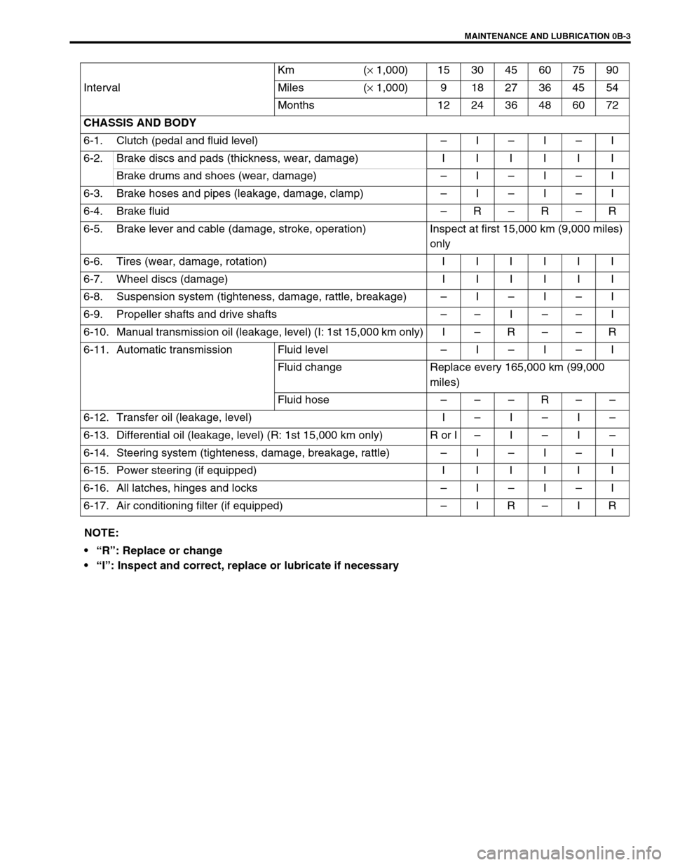
IntervalKm (× 1,000) 153045607590
Miles (× 1,000) 9 18 27 36 45 54
Months 12 24 36 48 60 72
CHASSIS AND BODY
6-1. Clutch (pedal and fluid level)–I–I–I
6-2.Brake discs and pads (thickness, wear, damage) IIIIII
Brake drums and shoes (wear, damage)–I–I–I
6-3. Brake hoses and pipes (leakage, damage, clamp)–I–I–I
6-4. Brake fluid–R–R–R
6-5. Brake lever and cable (damage, stroke, operation) Inspect at first 15,000 km (9,000 miles)
only
6-6.Tires (wear, damage, rotation) IIIIII
6-7.Wheel discs (damage) IIIIII
6-8. Suspension system (tighteness, damage, rattle, breakage)–I–I–I
6-9. Propeller shafts and drive shafts––I––I
6-10. Manual transmission oil (leakage, level) (I: 1st 15,000 km only) I–R––R
6-11. Automatic transmission Fluid level –I–I–I
Fluid change Replace every 165,000 km (99,000
miles)
Fluid hose–––R––
6-12. Transfer oil (leakage, level) I–I–I–
6-13. Differential oil (leakage, level) (R: 1st 15,000 km only) R or I–I–I–
6-14. Steering system (tighteness, damage, breakage, rattle)–I–I–I
6-15.Power steering (if equipped) IIIIII
6-16. All latches, hinges and locks–I–I–I
6-17. Air conditioning filter (if equipped)–IR–IR
NOTE:
“R”: Replace or change
“I”: Inspect and correct, replace or lubricate if necessary
Page 17 of 656

0B-4 MAINTENANCE AND LUBRICATION
Maintenance Recommended under Severe Driving Conditions
If the vehicle is usually used under the conditions corresponding to any severe condition code given below, it is
recommended that applicable maintenance operation be performed at the particular interval as given in the
chart below.
Severe condition code :
A: Repeated short trips E: Repeated short trips in extremely cold weather
B: Driving on rough and/or muddy roads F: Leaded fuel use
C: Driving on dusty roads G: – – – – – –
– –
D: Driving in extremely cold weather
and/or salted roadsH: Trailer towing (if admitted)
Severe
Condition CodeMaintenanceMaintenance
OperationMaintenance Interval
– B CD – – –ITEM 1-1
Drive belt (V-rib belt)IEvery 15,000 km
(9,000 miles) or 12 months
REvery 45,000 km
(27,000 miles) or 36 months
A – CDEF – HITEM 1-4
Engine oil and oil filterREvery 5,000 km
(3,000 miles) or 4 months
– B– – – – – –ITEM 1-6
Exhaust pipe mountingsIEvery 15,000 km
(9,000 miles) or 12 months
– – C – – – – – ITEM 3-1
Air cleaner filter *1IEvery 2,500 km
(1,5000 miles)
REvery 30,000 km
(18,000 miles) or 24 months
ABC–EF–HITEM 2-1
Spark plugsNickel plug REvery 10,000 km
(6,000 miles) or 8 months
Iridium plug REvery 30,000 km
(18,000 miles) or 24 months
– B – D E – – HITEM 6-9
Propeller shafts and drive shafts IEvery 15,000 km
(9,000 miles) or 12 months
– B – – E – – HITEM 6-10, 6-12, 6-13
Manual transmission,
transfer and differential oilREvery 30,000 km
(18,000 miles) or 24 months
– B – – E – – HITEM 6-11
Automatic transmission fluid REvery 30,000 km
(18,000 miles) or 24 months
– B – – – – – – ITEM 6-8
Suspension bolts and nutsTEvery 15,000 km
(9,000 miles) or 12 months
– B C D – – – HITEM 6-7
Wheel bearingIEvery 15,000 km
(9,000 miles) or 12 months
– – CD – – – –ITEM 6-17
Air conditioning filter *2
(if equipped)IEvery 15,000 km
(9,000 miles) or 12 months
REvery 45,000 km
(27,000 miles) or 36 months
NOTE:
“I”: Inspect and correct, replace or lubricate if necessary
”R”: Replace or change
”T”: Tighten to the specified torque
*1: Inspect or replace more frequently if necessary.
*2: Clean or replace more frequently if the air from the air conditioning decreases.
Page 64 of 656
AIR CONDITIONING (OPTIONAL) 1B-39
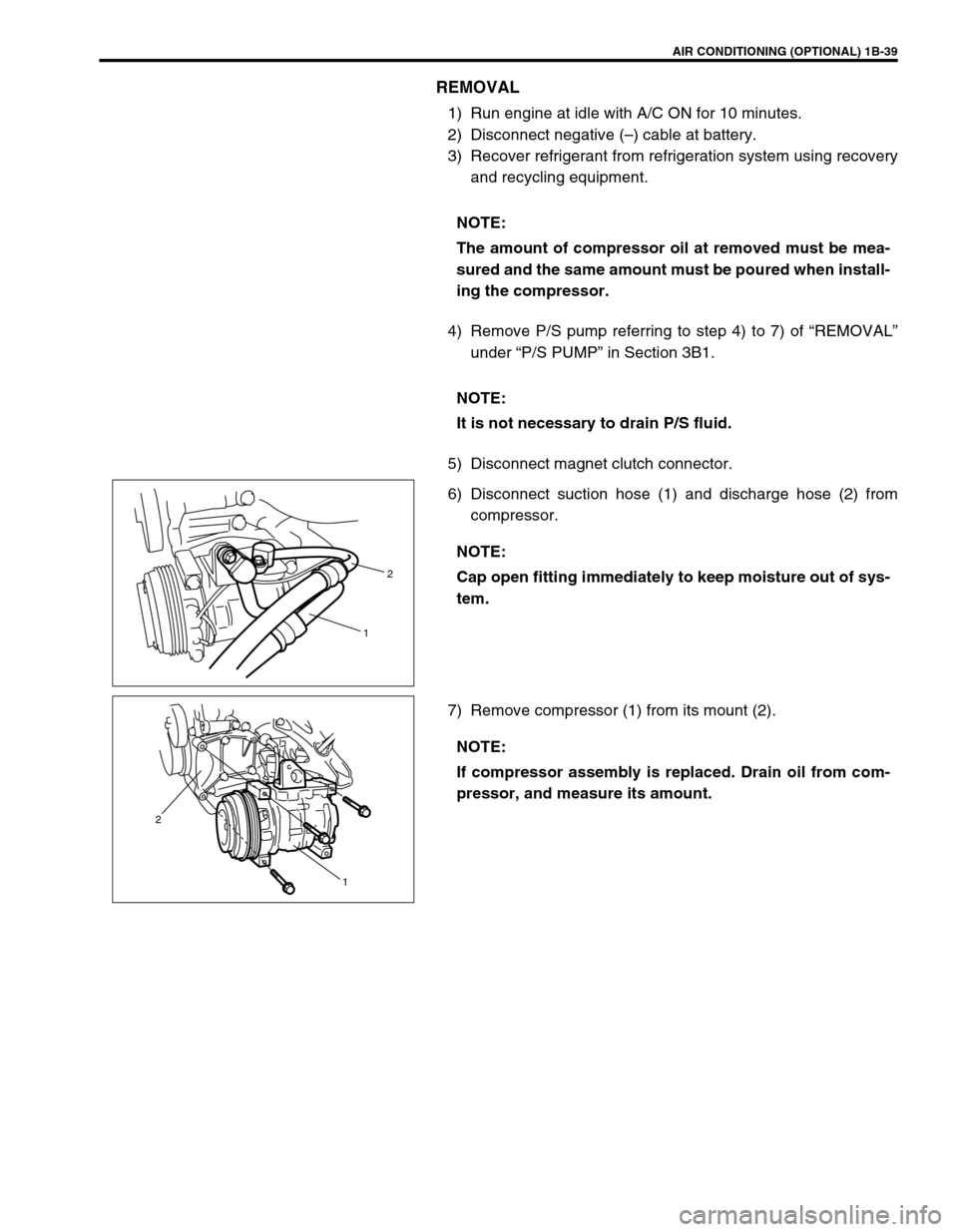
REMOVAL
1) Run engine at idle with A/C ON for 10 minutes.
2) Disconnect negative (–) cable at battery.
3) Recover refrigerant from refrigeration system using recovery
and recycling equipment.
4) Remove P/S pump referring to step 4) to 7) of “REMOVAL”
under “P/S PUMP” in Section 3B1.
5) Disconnect magnet clutch connector.
6) Disconnect suction hose (1) and discharge hose (2) from
compressor.
7) Remove compressor (1) from its mount (2).NOTE:
The amount of compressor oil at removed must be mea-
sured and the same amount must be poured when install-
ing the compressor.
NOTE:
It is not necessary to drain P/S fluid.
NOTE:
Cap open fitting immediately to keep moisture out of sys-
tem.
2
1
NOTE:
If compressor assembly is replaced. Drain oil from com-
pressor, and measure its amount.
1 2
Page 74 of 656
POWER STEERING (P/S) SYSTEM 3B1-3
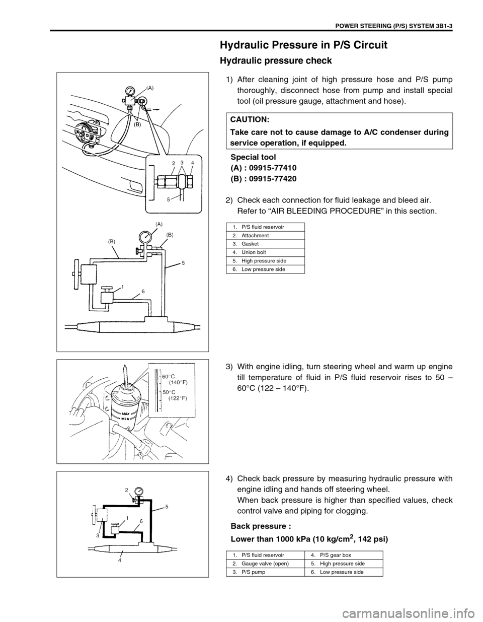
Hydraulic Pressure in P/S Circuit
Hydraulic pressure check
1) After cleaning joint of high pressure hose and P/S pump
thoroughly, disconnect hose from pump and install special
tool (oil pressure gauge, attachment and hose).
Special tool
(A) : 09915-77410
(B) : 09915-77420
2) Check each connection for fluid leakage and bleed air.
Refer to “AIR BLEEDING PROCEDURE” in this section.
3) With engine idling, turn steering wheel and warm up engine
till temperature of fluid in P/S fluid reservoir rises to 50 –
60°C (122 – 140°F).
4) Check back pressure by measuring hydraulic pressure with
engine idling and hands off steering wheel.
When back pressure is higher than specified values, check
control valve and piping for clogging.
Back pressure :
Lower than 1000 kPa (10 kg/cm
2, 142 psi) CAUTION:
Take care not to cause damage to A/C condenser during
service operation, if equipped.
1. P/S fluid reservoir
2. Attachment
3. Gasket
4. Union bolt
5. High pressure side
6. Low pressure side
1. P/S fluid reservoir 4. P/S gear box
2. Gauge valve (open) 5. High pressure side
3. P/S pump 6. Low pressure side
Page 75 of 656
3B1-4 POWER STEERING (P/S) SYSTEM
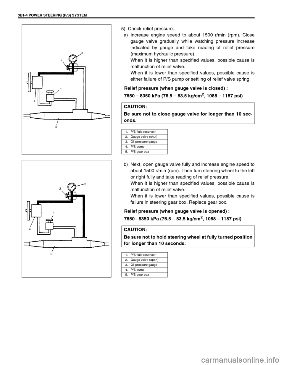
5) Check relief pressure.
a) Increase engine speed to about 1500 r/min (rpm). Close
gauge valve gradually while watching pressure increase
indicated by gauge and take reading of relief pressure
(maximum hydraulic pressure).
When it is higher than specified values, possible cause is
malfunction of relief valve.
When it is lower than specified values, possible cause is
either failure of P/S pump or settling of relief valve spring.
Relief pressure (when gauge valve is closed) :
7650 – 8350 kPa (76.5 – 83.5 kg/cm
2, 1088 – 1187 psi)
b) Next, open gauge valve fully and increase engine speed to
about 1500 r/min (rpm). Then turn steering wheel to the left
or right fully and take reading of relief pressure.
When it is higher than specified values, possible cause is
malfunction of relief valve.
When it is lower than specified values, possible cause is
failure in steering gear box. Replace gear box.
Relief pressure (when gauge valve is opened) :
7650– 8350 kPa (76.5 – 83.5 kg/cm
2, 1088 – 1187 psi) CAUTION:
Be sure not to close gauge valve for longer than 10 sec-
onds.
1. P/S fluid reservoir
2. Gauge valve (shut)
3. Oil pressure gauge
4. P/S pump
5. P/S gear box
CAUTION:
Be sure not to hold steering wheel at fully turned position
for longer than 10 seconds.
1. P/S fluid reservoir
2. Gauge valve (open)
3. Oil pressure gauge
4. P/S pump
5. P/S gear box
Page 95 of 656

3E-6 REAR SUSPENSION
5) Apply thread lock cement to thread of propeller shaft flange
bolt if reused. Install propeller shaft to joint flange aligning
match marks and torque flange nuts to specification.
“A” : Cement 99000-32110
Tightening torque
Propeller shaft nut (a) :
60 N·m (6.0 kg-m, 43.5 lb-ft)
Tightening Torque Specification
Required Service Material
Fastening partTightening torque
Nm kg-m lb-ft
Shock absorber nut 29 2.9 21.0
Shock absorber lower nut 85 8.5 61.5
Lower rod bolt and nut 100 10.0 72.5
Upper rod bolt and nut 100 10.0 72.5
Lateral rod bolt 100 10.0 72.5
Differential carrier bolt 55 5.5 40.0
Propeller shaft nut 60 6.0 43.5
Brake pipe flare nut 16 1.6 11.5
Bearing retainer nut 50 5.0 36.5
Differentiation gear oil filler & drain plug (filler plug) 50 5.0 36.5
Differentiation gear oil filler & drain plug (drain plug) 27 2.7 16.0
Wheel nut 100 10.0 72.5
Wheel speed sensor bolt 21 2.1 15.5
MaterialRecommended SUZUKI product
(Part Number)Use
Lithium grease SUZUKI SUPER GREASE A
(99000-25010)Oil seal lip
Brake fluid DOT 3Brake reservoir tank
Sealant SUZUKI BOND NO. 1215
(99000-31110)Joint seam of axle and brake back plate
Joint seam of bearing retainer and brake
back plate
Joint seam of differential carrier and axle
housing
Drain plug
Mating surface of oil seal and axle housing
Gear oil For gear oil information, refer to Section 7FDifferential gear (Rear axle housing)
Thread lock
cementTHREAD LOCK CEMENT SUPER 1322
(99000-32110)Rear propeller shaft flange bolts
Page 107 of 656
5-2 BRAKES
Diagnosis
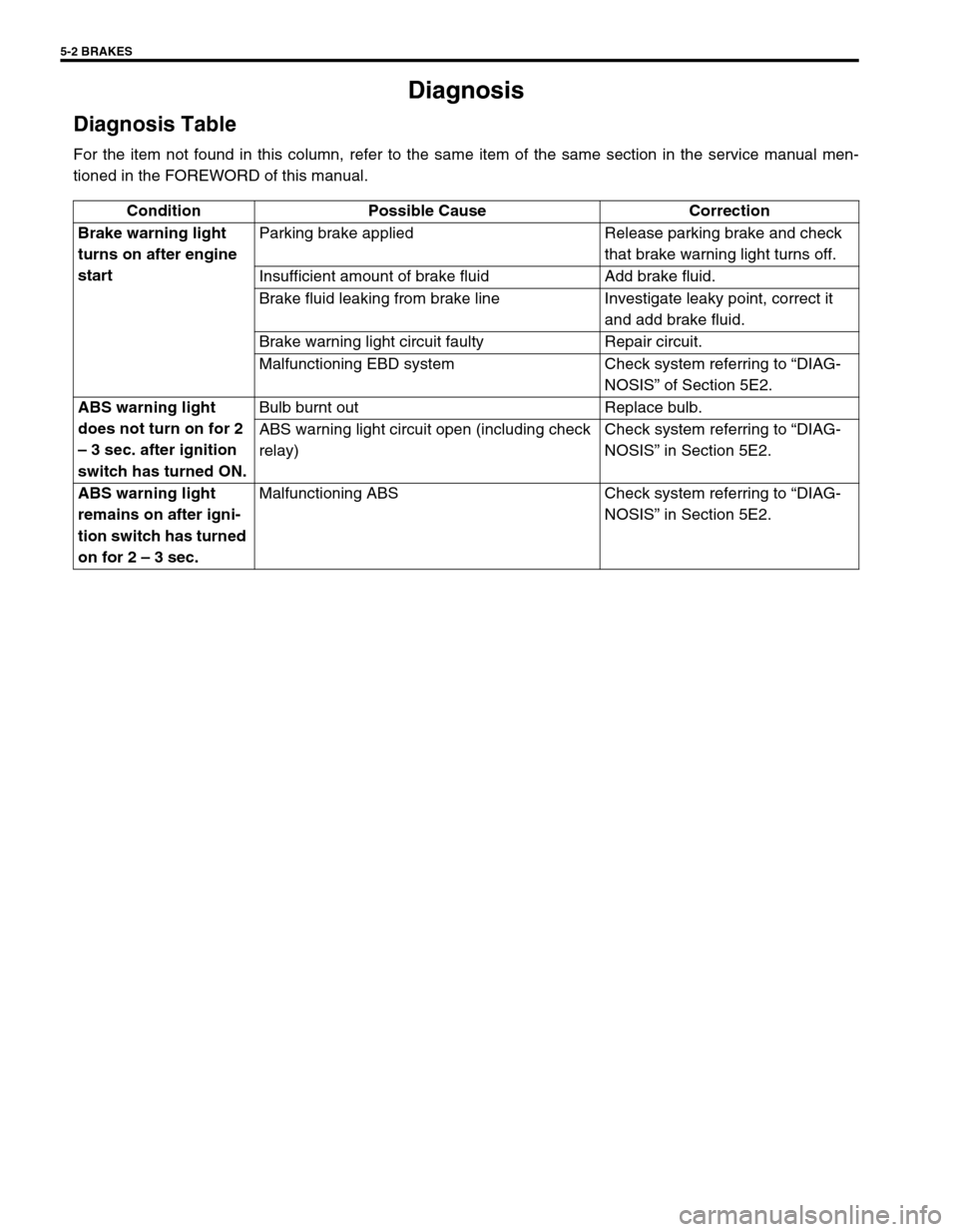
Diagnosis Table
For the item not found in this column, refer to the same item of the same section in the service manual men-
tioned in the FOREWORD of this manual.
Condition Possible Cause Correction
Brake warning light
turns on after engine
startParking brake applied Release parking brake and check
that brake warning light turns off.
Insufficient amount of brake fluid Add brake fluid.
Brake fluid leaking from brake line Investigate leaky point, correct it
and add brake fluid.
Brake warning light circuit faulty Repair circuit.
Malfunctioning EBD system Check system referring to “DIAG-
NOSIS” of Section 5E2.
ABS warning light
does not turn on for 2
– 3 sec. after ignition
switch has turned ON.Bulb burnt out Replace bulb.
ABS warning light circuit open (including check
relay)Check system referring to “DIAG-
NOSIS” in Section 5E2.
ABS warning light
remains on after igni-
tion switch has turned
on for 2 – 3 sec.Malfunctioning ABS Check system referring to “DIAG-
NOSIS” in Section 5E2.
Page 109 of 656
5A-2 BRAKES PIPE/HOSE/MASTER CYLINDER
General Description
Master Cylinder Assembly
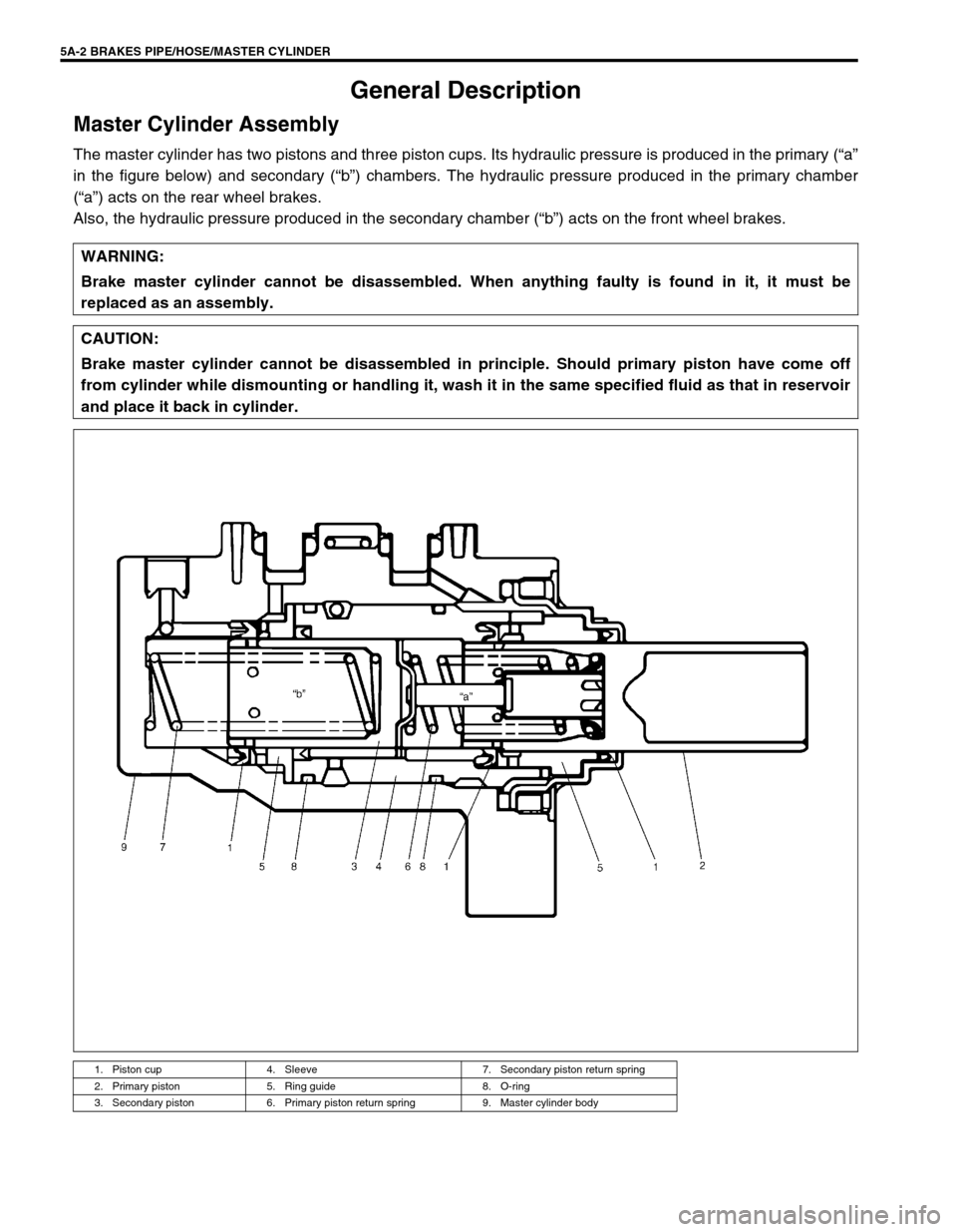
The master cylinder has two pistons and three piston cups. Its hydraulic pressure is produced in the primary (“a”
in the figure below) and secondary (“b”) chambers. The hydraulic pressure produced in the primary chamber
(“a”) acts on the rear wheel brakes.
Also, the hydraulic pressure produced in the secondary chamber (“b”) acts on the front wheel brakes.
WARNING:
Brake master cylinder cannot be disassembled. When anything faulty is found in it, it must be
replaced as an assembly.
CAUTION:
Brake master cylinder cannot be disassembled in principle. Should primary piston have come off
from cylinder while dismounting or handling it, wash it in the same specified fluid as that in reservoir
and place it back in cylinder.
1. Piston cup 4. Sleeve 7. Secondary piston return spring
2. Primary piston 5. Ring guide 8. O-ring
3. Secondary piston 6. Primary piston return spring 9. Master cylinder body