1999 SUZUKI GRAND VITARA Engine and emission control system
[x] Cancel search: Engine and emission control systemPage 4 of 656

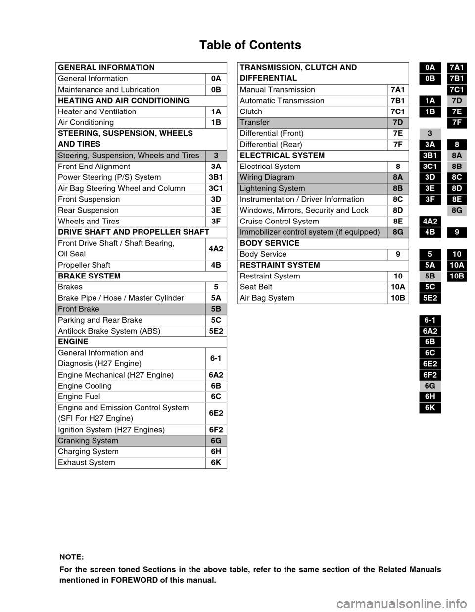
Table of Contents
GENERAL INFORMATION TRANSMISSION, CLUTCH AND
DIFFERENTIAL0A7A1
General Information0A
0B7B1
Maintenance and Lubrication0B
Manual Transmission7A1
7C1
HEATING AND AIR CONDITIONING
Automatic Transmission7B1
1A7D
Heater and Ventilation1A
Clutch7C1
1B7E
Air Conditioning1B
Transfer7D7F
STEERING, SUSPENSION, WHEELS
AND TIRESDifferential (Front)7E
3
Differential (Rear)7F
3A8
Steering, Suspension, Wheels and Tires3 ELECTRICAL SYSTEM3B18A
Front End Alignment3A
Electrical System8
3C18B
Power Steering (P/S) System3B1
Wiring Diagram8A3D8C
Air Bag Steering Wheel and Column3C1
Lightening System8B3E8D
Front Suspension3D
Instrumentation / Driver Information8C
3F8E
Rear Suspension3E
Windows, Mirrors, Security and Lock8D
8G
Wheels and Tires3F
Cruise Control System8E
4A2
DRIVE SHAFT AND PROPELLER SHAFT
Immobilizer control system (if equipped)8G4B9
Front Drive Shaft / Shaft Bearing,
Oil Seal4A2BODY SERVICE
Body Service9
510
Propeller Shaft4B RESTRAINT SYSTEM
5A10A
BRAKE SYSTEM
Restraint System10
5B10B
Brakes5
Seat Belt10A
5C
Brake Pipe / Hose / Master Cylinder5A
Air Bag System10B
5E2
Front Brake5B
Parking and Rear Brake5C
6-1
Antilock Brake System (ABS)5E2
6A2
ENGINE
6B
General Information and
Diagnosis (H27 Engine)6-1
6C
6E2
Engine Mechanical (H27 Engine)6A2
6F2
Engine Cooling6B
6G
Engine Fuel6C
6H
Engine and Emission Control System
(SFI For H27 Engine)6E2
6K
Ignition System (H27 Engines)6F2
Cranking System6G
Charging System6H
Exhaust System6K
NOTE:
For the screen toned Sections in the above table, refer to the same section of the Related Manuals
mentioned in FOREWORD of this manual.
Page 14 of 656

MAINTENANCE AND LUBRICATION 0B-1
0B
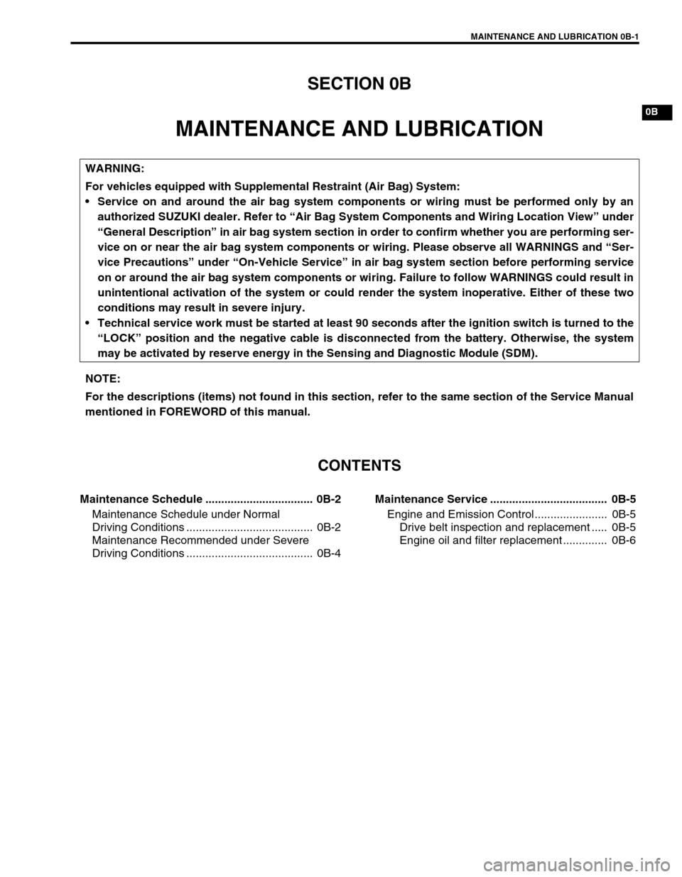
SECTION 0B
MAINTENANCE AND LUBRICATION
CONTENTS
Maintenance Schedule .................................. 0B-2
Maintenance Schedule under Normal
Driving Conditions ........................................ 0B-2
Maintenance Recommended under Severe
Driving Conditions ........................................ 0B-4Maintenance Service ..................................... 0B-5
Engine and Emission Control....................... 0B-5
Drive belt inspection and replacement ..... 0B-5
Engine oil and filter replacement .............. 0B-6
WARNING:
For vehicles equipped with Supplemental Restraint (Air Bag) System:
Service on and around the air bag system components or wiring must be performed only by an
authorized SUZUKI dealer. Refer to “Air Bag System Components and Wiring Location View” under
“General Description” in air bag system section in order to confirm whether you are performing ser-
vice on or near the air bag system components or wiring. Please observe all WARNINGS and “Ser-
vice Precautions” under “On-Vehicle Service” in air bag system section before performing service
on or around the air bag system components or wiring. Failure to follow WARNINGS could result in
unintentional activation of the system or could render the system inoperative. Either of these two
conditions may result in severe injury.
Technical service work must be started at least 90 seconds after the ignition switch is turned to the
“LOCK” position and the negative cable is disconnected from the battery. Otherwise, the system
may be activated by reserve energy in the Sensing and Diagnostic Module (SDM).
NOTE:
For the descriptions (items) not found in this section, refer to the same section of the Service Manual
mentioned in FOREWORD of this manual.
Page 15 of 656

0B-2 MAINTENANCE AND LUBRICATION
Maintenance Schedule
Maintenance Schedule under Normal Driving Conditions
NOTE:
This interval should be judged by odometer reading or months, whichever comes first.
This table includes service as scheduled up to 90,000 km (54,000 miles) mileage. Beyond 90,000 km
(54,000 miles), carry out the same services at the same intervals respectively.
IntervalKm (× 1,000) 15 30 45 60 75 90
Miles (× 1,000) 9 18 27 36 45 54
Months 12 24 36 48 60 72
ENGINE
1-1. Drive belt V-rib belt (Flat type)––I––R
1-4. Engine oil and oil filter R R R R R R
1-5. Engine coolant––R––R
1-6. Exhaust system–I–I–I
IGNITION SYSTEM
2-1. Spark plugs When
unleaded
fuel is usedVehicle without
HO2SNickel plug –R–R–R
Iridium plug–––R––
Vehicle with
HO2SNickel plug ––R––R
Iridium plug Replace every 105,000 km or
63,000 miles
When leaded fuel is used, refer to “MAINTENANCE RECOMMENDED UNDER
SERVER DRIVING CONDITIONS” in this section.
FUEL SYSTEM
3-1. Air cleaner filter I I R I I R
3-2. Fuel lines and connections–I–I–I
3-3. Fuel filter Replace every 105,000 km or
63,000 miles
3-4. Fuel tank––I––I
EMISSION CONTROL SYSTEM
4-1. Crankcase ventilation hoses and connections (Vehicle without
HO2S)––I––I
4-2. PCV valve Vehicle without HO2S––I––I
Vehicle with HO2S–––––I
4-3. Fuel evaporative emission con-
trol systemVehicle without HO2S–I–I–I
Vehicle with HO2S–––––I
NOTE:
“R”: Replace or change
“I”: Inspect and correct, replace or lubricate if necessary
For Sweden, item 2-1, 4-2 and 4-3 should be performed by odometer reading only.
For Item 2-1. Nickel spark plugs, replace every 50,000 km if the local law requires.
Nickel spark plug: BKR6E-11 or K20PR-U11
Iridium spark plug: IFR5J11 or SK16PR11
Page 167 of 656

6-1-6 ENGINE GENERAL INFORMATION AND DIAGNOSIS (H27 ENGINE)
Engine Diagnosis
General Description
This vehicle is equipped with an engine and emission control system which are under control of ECM (PCM).
The engine and emission control system in this vehicle are controlled by ECM (PCM). ECM (PCM) has an On-
Board Diagnostic system which detects a malfunction in this system and abnormality of those parts that influ-
ence the engine exhaust emission. When diagnosing engine troubles, be sure to have full understanding of the
outline of “ON-BOARD DIAGNOSTIC SYSTEM” and each item in “PRECAUTION IN DIAGNOSING TROUBLE”
and execute diagnosis according to “ENGINE DIAGNOSTIC FLOW TABLE” in this section.
There is a close relationship between the engine mechanical, engine cooling system, ignition system, exhaust
system, etc. and the engine and emission control system in their structure and operation. In case of an engine
trouble, even when the malfunction indicator lamp (MIL) doesn’t turn ON, it should be diagnosed according to
“ENGINE DIAGNOSTIC FLOW TABLE” in this section.
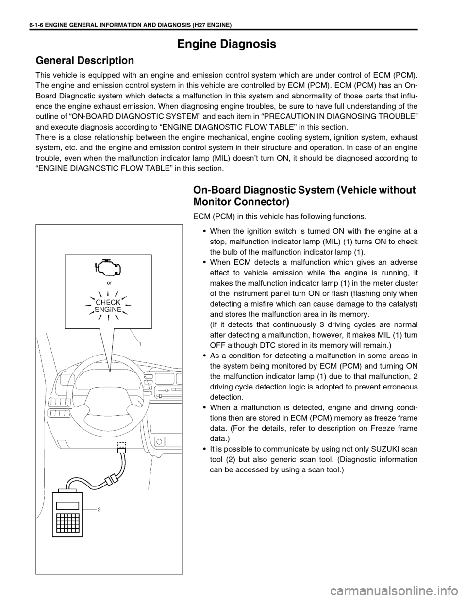
On-Board Diagnostic System (Vehicle without
Monitor Connector)
ECM (PCM) in this vehicle has following functions.
When the ignition switch is turned ON with the engine at a
stop, malfunction indicator lamp (MIL) (1) turns ON to check
the bulb of the malfunction indicator lamp (1).
When ECM detects a malfunction which gives an adverse
effect to vehicle emission while the engine is running, it
makes the malfunction indicator lamp (1) in the meter cluster
of the instrument panel turn ON or flash (flashing only when
detecting a misfire which can cause damage to the catalyst)
and stores the malfunction area in its memory.
(If it detects that continuously 3 driving cycles are normal
after detecting a malfunction, however, it makes MIL (1) turn
OFF although DTC stored in its memory will remain.)
As a condition for detecting a malfunction in some areas in
the system being monitored by ECM (PCM) and turning ON
the malfunction indicator lamp (1) due to that malfunction, 2
driving cycle detection logic is adopted to prevent erroneous
detection.
When a malfunction is detected, engine and driving condi-
tions then are stored in ECM (PCM) memory as freeze frame
data. (For the details, refer to description on Freeze frame
data.)
It is possible to communicate by using not only SUZUKI scan
tool (2) but also generic scan tool. (Diagnostic information
can be accessed by using a scan tool.)
Page 170 of 656

ENGINE GENERAL INFORMATION AND DIAGNOSIS (H27 ENGINE) 6-1-9
On-Board Diagnostic System (Vehicle with
Monitor Connector)
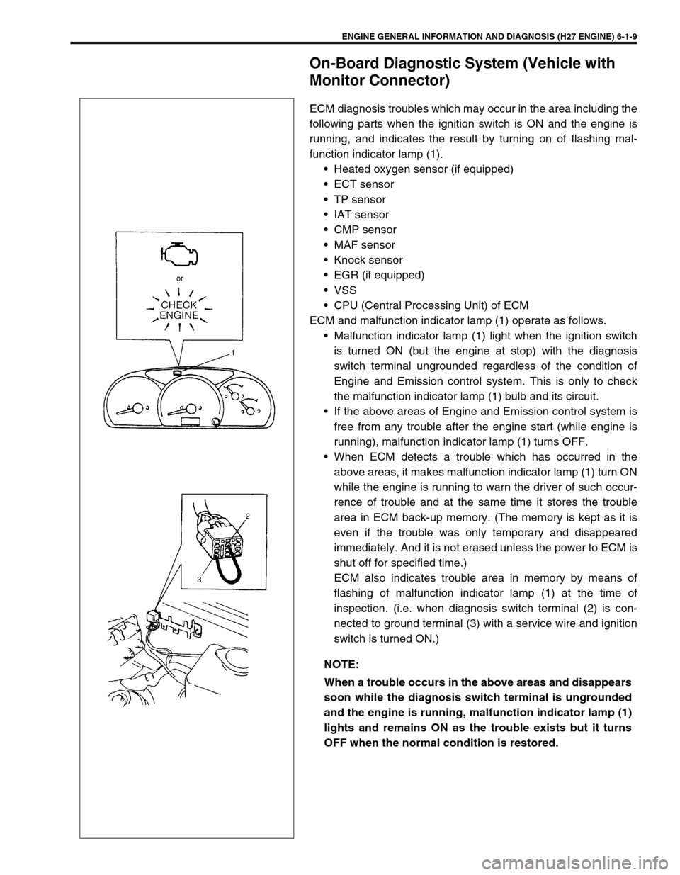
ECM diagnosis troubles which may occur in the area including the
following parts when the ignition switch is ON and the engine is
running, and indicates the result by turning on of flashing mal-
function indicator lamp (1).
• Heated oxygen sensor (if equipped)
•ECT sensor
•TP sensor
• IAT sensor
• CMP sensor
•MAF sensor
• Knock sensor
• EGR (if equipped)
•VSS
• CPU (Central Processing Unit) of ECM
ECM and malfunction indicator lamp (1) operate as follows.
• Malfunction indicator lamp (1) light when the ignition switch
is turned ON (but the engine at stop) with the diagnosis
switch terminal ungrounded regardless of the condition of
Engine and Emission control system. This is only to check
the malfunction indicator lamp (1) bulb and its circuit.
• If the above areas of Engine and Emission control system is
free from any trouble after the engine start (while engine is
running), malfunction indicator lamp (1) turns OFF.
• When ECM detects a trouble which has occurred in the
above areas, it makes malfunction indicator lamp (1) turn ON
while the engine is running to warn the driver of such occur-
rence of trouble and at the same time it stores the trouble
area in ECM back-up memory. (The memory is kept as it is
even if the trouble was only temporary and disappeared
immediately. And it is not erased unless the power to ECM is
shut off for specified time.)
ECM also indicates trouble area in memory by means of
flashing of malfunction indicator lamp (1) at the time of
inspection. (i.e. when diagnosis switch terminal (2) is con-
nected to ground terminal (3) with a service wire and ignition
switch is turned ON.)
NOTE:
When a trouble occurs in the above areas and disappears
soon while the diagnosis switch terminal is ungrounded
and the engine is running, malfunction indicator lamp (1)
lights and remains ON as the trouble exists but it turns
OFF when the normal condition is restored.
Page 181 of 656

6-1-20 ENGINE GENERAL INFORMATION AND DIAGNOSIS (H27 ENGINE)
P0174 Fuel system too lean (Bank 2)Short term fuel trim or total fuel trim
(short and long terms added) is larger
than specification for specified time or
longer. (Fuel trim toward rich side is
large.)2 driving
cyclesNot
applicable
P0175 Fuel system too rich (Bank 2)Short term fuel trim or total fuel trim
(short and long terms added) is
smaller than specification for specified
time or longer. (Fuel trim toward lean
side is large.)2 driving
cyclesNot
applicable
P0300
P0301
P0302
P0303
P0304
P0305
P0306Random misfire detected
Cylinder 1 misfire detected
Cylinder 2 misfire detected
Cylinder 3 misfire detected
Cylinder 4 misfire detected
Cylinder 5 misfire detected
Cylinder 6 misfire detectedMisfire of such level as to cause dam-
age to three way catalystMIL flashing
during mis-
fire detec-
tionNot
applicable
Misfire of such level as to deteriorate
emission but not to cause damage to
three way catalyst2 driving
cyclesNot
applicable
P0325
(No.43)Knock sensor circuit malfunc-
tionSensor output too low
1 driving
cycle1 driving
cycle
Sensor output too high
P0335Crankshaft position sensor cir-
cuit malfunctionNo signal during engine running and
CMP sensor signal inputting1 driving
cycleNot
applicable
P0340
(No.42)Camshaft position sensor cir-
cuit malfunctionNo signal for 3 sec. during engine
cranking, REF signal pattern incor-
rect or POS signal voltage too high or
too low1 driving
cycleNot
applicable
P0400Exhaust gas recirculation flow
malfunction detectedExcessive or insufficient EGR flow.2 driving
cyclesNot
applicable
P0403
(No.51)EGR valve circuit malfunctionEGR valve electrical circuit open or
shot to ground1 driving
cycle1 driving
cycle
P0420Catalyst system efficiency
below threshold (Bank 1)Output waveforms of HO2S-1 and
HO2S-2 are similar.
(Time from output voltage change of
HO2S-1 to that of HO2S-2 is shorter
than specification.)2 driving
cyclesNot
applicable
P0430Catalyst system efficiency
below threshold (Bank 2)Output waveforms of HO2S-1 and
HO2S-2 are similar.
(Time from output voltage change of
HO2S-1 to that of HO2S-2 is shorter
than specification.)2 driving
cyclesNot
applicable
P0443Purge control valve circuit
malfunctionPurge control valve circuit is open or
shorted to ground.2 driving
cyclesNot
applicable
P0500
(No.24)Vehicle speed sensor mal-
functionNo signal while running in “D” range
or during fuel cut at decelerating.2 driving
cycles1 driving
cycle DTC NO. DETECTED ITEMDETECTING CONDITION
(DTC will set when detecting : )MIL
(vehicle
without
monitor
connector)MIL
(vehicle
with
monitor
connector)
Page 193 of 656

6-1-32 ENGINE GENERAL INFORMATION AND DIAGNOSIS (H27 ENGINE)
Improper engine idling
or engine fails to idleFaulty spark plug Spark plugs in Section 6F2.
Faulty ignition coil with ignitor Ignition coil in Section 6F2.
Fuel pressure out of specification “DIAG. FLOW TABLE B-3” in this
section.
Engine overheating Refer to “OVERHEATING” in this
table.
Maladjusted TP sensor installation angle if
adjustableTP sensor in Section 6E2.
Faulty idle air control system “DIAG. FLOW TABLE B-4” in this
section.
Faulty FIA (fast idle air) valve FIA valve in Section 6E2.
Faulty evaporative emission control system EVAP control system in Section
6E2.
Faulty EGR system “DTC P0400 DIAG. FLOW TABLE”
in this section.
Faulty injector Fuel injection in Section 6E2.
Faulty ECT sensor, TP sensor or MAF sensor ECT sensor, TP sensor or MAF
sensor in Section 6E2.
Faulty ECM (PCM) Inspection of ECM (PCM) and its
circuit in this section.
Low compression Refer to the same item in “HARD
STARTING” of this table.
Malfunctioning PCV valve PCV system inspection in Section
6E2.
Engine hesitates
(Momentary lack of
response as the accel-
erator is depressed.
Can occur at all vehi-
cle speeds.
Usually most severe
when first trying to
make the vehicle
move, as from a stop
sign.)Spark plug faulty or plug gap as out of adjust-
mentSpark plugs in Section 6F2.
Fuel pressure out of specification
(clogged fuel filter, faulty fuel pressure regula-
tor, clogged fuel filter, hose or pipe)“DIAG. FLOW TABLE B-3” in this
section.
Engine overheating Refer to “OVERHEATING” in this
table.
Faulty EGR system “DTC P0400 DIAG. FLOW TABLE”
in this section.
Faulty injector Fuel injector in Section 6E2.
Faulty TP sensor, ECT sensor or MAF sensor TP sensor, ECT sensor or MAF
sensor in Section 6E2.
Faulty ECM (PCM) Inspection of ECM (PCM) and its
circuit in this section.
Low compression Refer to the same item in “HARD
STARTING” of this table. Condition Possible Cause Correction
Page 334 of 656

ENGINE AND EMISSION CONTROL SYSTEM (SEQUENTIAL MULTIPORT FUEL INJECTION FOR H27 ENGINE) 6E2-1
6E2
SECTION 6E2
ENGINE AND EMISSION CONTROL SYSTEM
(SEQUENTIAL MULTIPORT FUEL INJECTION
FOR H27 ENGINE)
CONTENTS
General Description ..................................... 6E2-2
System Flow ............................................... 6E2-3
System Diagram ......................................... 6E2-4
Air Intake System ....................................... 6E2-6
Fuel Delivery System ................................. 6E2-7
Electronic Control System .......................... 6E2-8
Engine and Emission Control Input/Output
Table ........................................................ 6E2-12
Diagnosis .................................................... 6E2-12
On-Vehicle Service..................................... 6E2-13
General .................................................... 6E2-13
Accelerator Cable Adjustment .................. 6E2-14
A/T Throttle Cable Adjustment
(A/T Vehicle) ............................................ 6E2-14Idle Speed/Idle Air Control (IAC) Duty
Inspection................................................. 6E2-15
[Using SUZUKI scan tool] .................... 6E2-15
[Not using SUZUKI scan tool]
(vehicle with monitor connector) .......... 6E2-16
Idle mixture inspection/adjustment
(vehicle without heated oxygen sensor) 6E2-17
Air Intake System ..................................... 6E2-18
Throttle body ........................................ 6E2-18
Idle air control valve (IAC valve) .......... 6E2-21
Fast idle air valve ................................. 6E2-22
Fuel Delivery System ............................... 6E2-23
Fuel pressure inspection ...................... 6E2-23
Fuel pump ............................................ 6E2-24
Fuel pressure regulator ........................ 6E2-25 WARNING:
For vehicles equipped with Supplemental Restraint (Air Bag) System:
Service on and around the air bag system components or wiring must be performed only by an
authorized SUZUKI dealer. Refer to “Air Bag System Components and Wiring Location View” under
“General Description” in air bag system section in order to confirm whether you are performing ser-
vice on or near the air bag system components or wiring. Please observe all WARNINGS and “Ser-
vice Precautions” under “On-Vehicle Service” in air bag system section before performing service
on or around the air bag system components or wiring. Failure to follow WARNINGS could result in
unintentional activation of the system or could render the system inoperative. Either of these two
conditions may result in severe injury.
Technical service work must be started at least 90 seconds after the ignition switch is turned to the
“LOCK” position and the negative cable is disconnected from the battery. Otherwise, the system
may be activated by reserve energy in the Sensing and Diagnostic Module (SDM).
NOTE:
Whether following systems (parts) are used in the particular vehicle or not depends on specifications.
Be sure to bear this in mind when performing service work.
Monitor connector
CKP sensor
MAP sensor
EGR valve
Heated oxygen sensor or CO adjusting resistor
Three way catalytic converter, Warm-up three way catalytic converter