1999 SUZUKI GRAND VITARA window switch
[x] Cancel search: window switchPage 35 of 656
1B-10 AIR CONDITIONING (OPTIONAL)
Performance Diagnosis
1) Confirm that vehicle and environmental conditions are as fol-
lows.
Vehicle is not exposed to direct sun.
Ambient temperature is within 15 - 35 °C (59 - 95 °F).
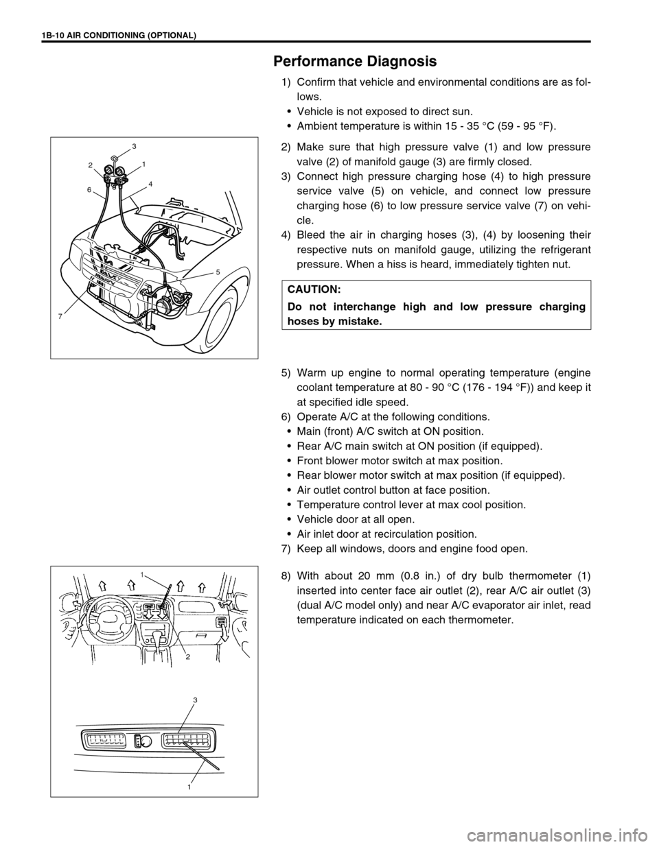
2) Make sure that high pressure valve (1) and low pressure
valve (2) of manifold gauge (3) are firmly closed.
3) Connect high pressure charging hose (4) to high pressure
service valve (5) on vehicle, and connect low pressure
charging hose (6) to low pressure service valve (7) on vehi-
cle.
4) Bleed the air in charging hoses (3), (4) by loosening their
respective nuts on manifold gauge, utilizing the refrigerant
pressure. When a hiss is heard, immediately tighten nut.
5) Warm up engine to normal operating temperature (engine
coolant temperature at 80 - 90 °C (176 - 194 °F)) and keep it
at specified idle speed.
6) Operate A/C at the following conditions.
Main (front) A/C switch at ON position.
Rear A/C main switch at ON position (if equipped).
Front blower motor switch at max position.
Rear blower motor switch at max position (if equipped).
Air outlet control button at face position.
Temperature control lever at max cool position.
Vehicle door at all open.
Air inlet door at recirculation position.
7) Keep all windows, doors and engine food open.
8) With about 20 mm (0.8 in.) of dry bulb thermometer (1)
inserted into center face air outlet (2), rear A/C air outlet (3)
(dual A/C model only) and near A/C evaporator air inlet, read
temperature indicated on each thermometer. CAUTION:
Do not interchange high and low pressure charging
hoses by mistake.
2
64
3
75 1
3
1
2
Page 190 of 656

ENGINE GENERAL INFORMATION AND DIAGNOSIS (H27 ENGINE) 6-1-29
EGR VALVE (%)
This parameter indicates opening rate of EGR valve which controls the amount of EGR flow.
A/C SWITCH (ON/OFF)
ON : Command for operation being output from A/C amplifier to compressor.
OFF : Command for operation not being output.
PSP SWITCH (ON/OFF)
ON : PSP switch detects P/S operation. (high P/S pressure)
OFF : PSP switch not detects P/S operation.
PNP SIGNAL (Transmission Range Switch, P/N or D range)
Whether the transmission range switch (P/N position switch) at P or N range or at R, D, 2 or L range is displayed.
If at P or N range, “P/N range” is displayed and if at R, D, 2 or L range, “D range” is displayed.
FUEL TANK LEVEL (%)
This parameter indicates approximate fuel level in the fuel tank. As the detectable range of the fuel level sensor
is set as 0 to 100 %, however, with some models whose fuel tank capacity is smaller, the indicated fuel level may
be only 70 % even when the fuel tank is full.
ELECTRIC LOAD (ON/OFF)
ON : Small light switch ON or rear window defogger switch ON.
OFF : Small light switch OFF and rear window defogger switch OFF.
VSS (4-A/T) (km/h, MPH)
It is computed by using pulse signals from vehicle speed sensor on 4-speed automatic transmission.
THROT POS LEVEL (Throttle Position Level For 4-A/T, “0”, “1”, “2”, “3”, “4”,“5”,“6” or “7”)
This parameter indicates which level (zone) the throttle valve opening is in.
The throttle opening is divided into 8 levels (zones) from “0” (about idle position) to “7” (about full open) and sig-
nals are assigned to each opening level (zone). PCM controls the automatic gear change of the automatic trans-
mission by using these signals according to the signal from the TP sensor.
GEAR POSITION (1ST, 2ND, 3RD or 4TH)
The gear position is determined on the basis of the command state signals generated from PCM to shift sole-
noids A and B (#1 and #2) and displayed as shown in the table below.
SHIFT SOL #1 CON/MON (Shift Solenoid #1, A Command/monitor, ON/OFF)
CON-ON : ON command being output to shift solenoid #1, A.
CON-OFF : ON command not being output.
MON-ON : Electricity being passed to shift solenoid #1, A.
MON-OFF : Electricity not being passed.SHIFT SOLENOID-A SHIFT SOLENOID-B
DISPLAY1ST ON OFF
2ND ON ON
3RD OFF ON
4TH OFF OFF
Page 510 of 656
BODY ELECTRICAL SYSTEM 8-1
6F1
6F2
6G
6H
6K
7A
8
6K
7C1
7D
7E
7F
8A
8D
8E
9
10
10A
10B
SECTION 8
BODY ELECTRICAL SYSTEM
Wiring System
(Harnesses, Connectors, Fuses, Relay, Switches, Grounds, System Circuit Diagram) .......... Section 8A
Lighting System .............................................................................................................................. Section 8B
Instrumententation and Driver Information .................................................................................. Section 8C
Windows, Mirrors, Security and Locks ......................................................................................... Section 8D
Immobilizer Control System............................................................................................................Section 8F
CONTENTS
General Description .......................................... 8-3
WARNING:
For vehicles equipped with Supplemental Restraint (Air Bag) System:
Service on and around the air bag system components or wiring must be performed only by an
authorized SUZUKI dealer. Refer to “Air Bag System Components and Wiring Location View” under
“General Description” in air bag system section in order to confirm whether you are performing ser-
vice on or near the air bag system components or wiring. Please observe all WARNINGS and “Ser-
vice Precautions” under “On-Vehicle Service” in air bag system section before performing service
on or around the air bag system components or wiring. Failure to follow WARNINGS could result in
unintentional activation of the system or could render the system inoperative. Either of these two
conditions may result in severe injury.
Technical service work must be started at least 90 seconds after the ignition switch is turned to the
“LOCK” position and the negative cable is disconnected from the battery. Otherwise, the system
may be activated by reserve energy in the Sensing and Diagnostic Module (SDM).
NOTE:
For the descriptions (items) not found in this section, refer to the same section of the Service Manual
mentioned in FOREWORD of this manual.
Page 518 of 656
WINDOWS, MIRRORS, SECURITY AND LOCKS 8D-1
8D
SECTION 8D
WINDOWS, MIRRORS, SECURITY AND LOCKS
CONTENTS
General Description ....................................... 8D-2
Rear Wiper and Washer (If Equipped) ......... 8D-2
On-Vehicle Service......................................... 8D-3
Windshield Wipers ....................................... 8D-3
Front wiper and washer ............................ 8D-3Rear Window Wiper and Washer
(For Vehicle with Cruise Control System) .... 8D-4
Rear Wiper and Washer Switch ............... 8D-4
Rear Window Wiper and Washer
(For Vehicle without Cruise Control
System) ........................................................ 8D-4
Rear Wiper Intermittent Relay...................... 8D-4
WARNING:
For vehicles equipped with Supplemental Restraint (Air Bag) System:
Service on and around the air bag system components or wiring must be performed only by an
authorized SUZUKI dealer. Refer to “Air Bag System Components and Wiring Location View” under
“General Description” in air bag system section in order to confirm whether you are performing ser-
vice on or near the air bag system components or wiring. Please observe all WARNINGS and “Ser-
vice Precautions” under “On-Vehicle Service” in air bag system section before performing service
on or around the air bag system components or wiring. Failure to follow WARNINGS could result in
unintentional activation of the system or could render the system inoperative. Either of these two
conditions may result in severe injury.
Technical service work must be started at least 90 seconds after the ignition switch is turned to the
“LOCK” position and the negative cable is disconnected from the battery. Otherwise, the system
may be activated by reserve energy in the Sensing and Diagnostic Module (SDM).
NOTE:
For the descriptions (items) not found in this section, refer to the same section of the Service Manual
mentioned in FOREWORD of this manual.
Page 521 of 656
8D-4 WINDOWS, MIRRORS, SECURITY AND LOCKS
Rear Window Wiper and Washer (For Vehicle with Cruise Control System)
INSPECTION
Rear Wiper and Washer Switch
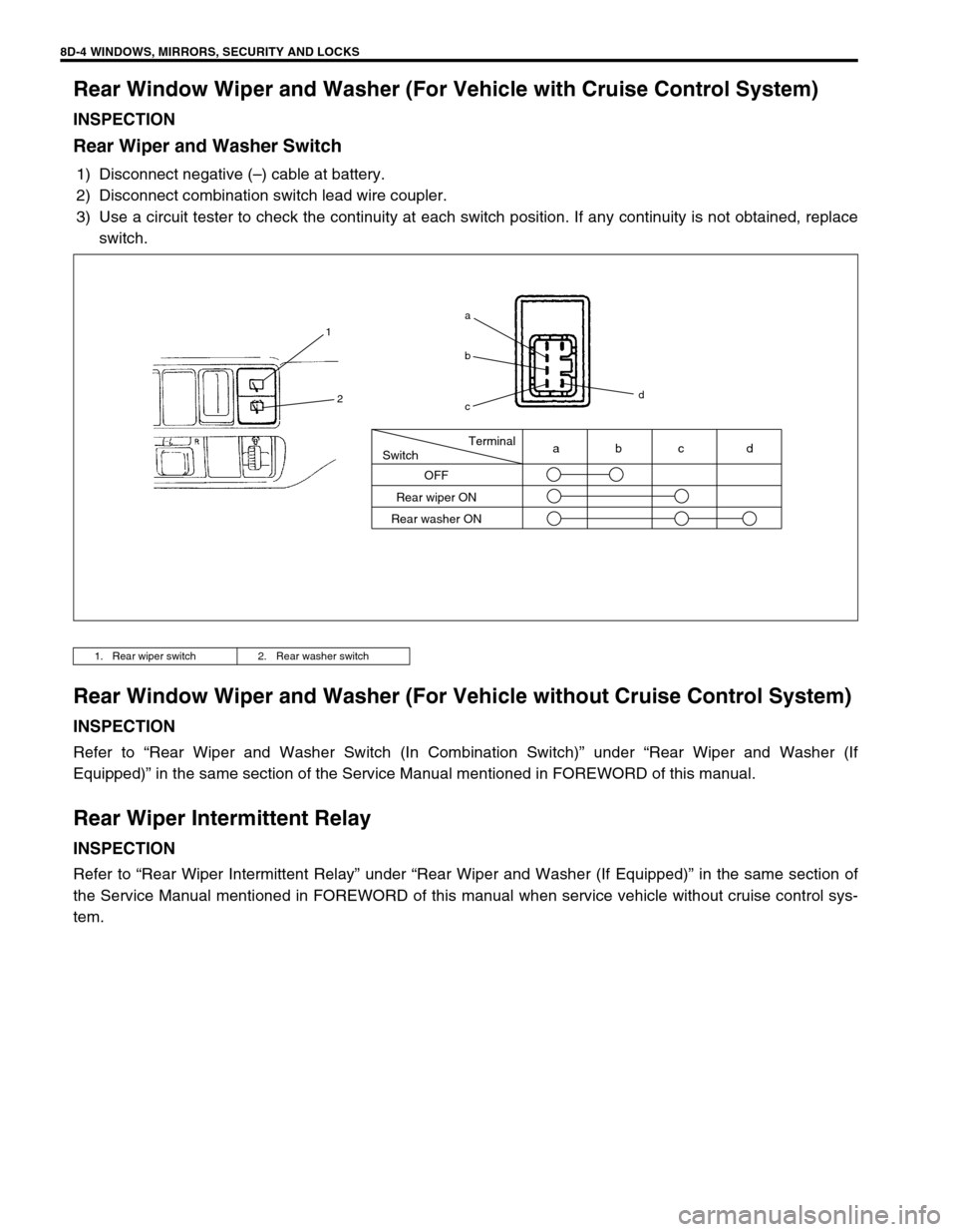
1) Disconnect negative (–) cable at battery.
2) Disconnect combination switch lead wire coupler.
3) Use a circuit tester to check the continuity at each switch position. If any continuity is not obtained, replace
switch.
Rear Window Wiper and Washer (For Vehicle without Cruise Control System)
INSPECTION
Refer to “Rear Wiper and Washer Switch (In Combination Switch)” under “Rear Wiper and Washer (If
Equipped)” in the same section of the Service Manual mentioned in FOREWORD of this manual.
Rear Wiper Intermittent Relay
INSPECTION
Refer to “Rear Wiper Intermittent Relay” under “Rear Wiper and Washer (If Equipped)” in the same section of
the Service Manual mentioned in FOREWORD of this manual when service vehicle without cruise control sys-
tem.
1. Rear wiper switch 2. Rear washer switch
Terminal
Switch
OFF
Rear wiper ON
Rear washer ONabc d
1
2
a
b
cd
Page 546 of 656
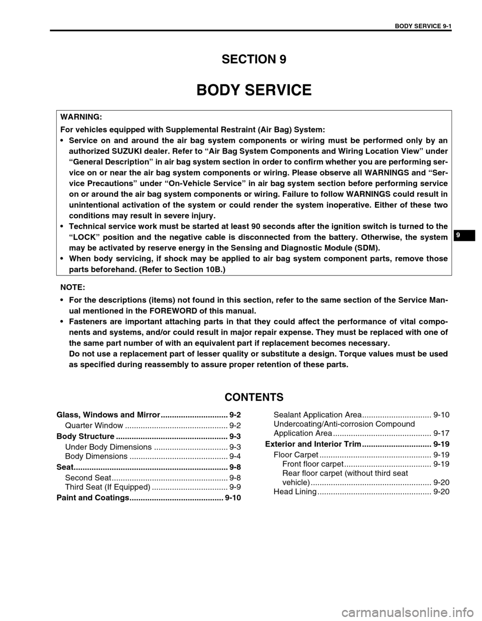
BODY SERVICE 9-1
9
SECTION 9
BODY SERVICE
CONTENTS
Glass, Windows and Mirror .............................. 9-2
Quarter Window .............................................. 9-2
Body Structure .................................................. 9-3
Under Body Dimensions ................................. 9-3
Body Dimensions ............................................ 9-4
Seat..................................................................... 9-8
Second Seat .................................................... 9-8
Third Seat (If Equipped) .................................. 9-9
Paint and Coatings.......................................... 9-10Sealant Application Area............................... 9-10
Undercoating/Anti-corrosion Compound
Application Area ............................................ 9-17
Exterior and Interior Trim ............................... 9-19
Floor Carpet .................................................. 9-19
Front floor carpet ....................................... 9-19
Rear floor carpet (without third seat
vehicle) ...................................................... 9-20
Head Lining ................................................... 9-20
WARNING:
For vehicles equipped with Supplemental Restraint (Air Bag) System:
Service on and around the air bag system components or wiring must be performed only by an
authorized SUZUKI dealer. Refer to “Air Bag System Components and Wiring Location View” under
“General Description” in air bag system section in order to confirm whether you are performing ser-
vice on or near the air bag system components or wiring. Please observe all WARNINGS and “Ser-
vice Precautions” under “On-Vehicle Service” in air bag system section before performing service
on or around the air bag system components or wiring. Failure to follow WARNINGS could result in
unintentional activation of the system or could render the system inoperative. Either of these two
conditions may result in severe injury.
Technical service work must be started at least 90 seconds after the ignition switch is turned to the
“LOCK” position and the negative cable is disconnected from the battery. Otherwise, the system
may be activated by reserve energy in the Sensing and Diagnostic Module (SDM).
When body servicing, if shock may be applied to air bag system component parts, remove those
parts beforehand. (Refer to Section 10B.)
NOTE:
For the descriptions (items) not found in this section, refer to the same section of the Service Man-
ual mentioned in the FOREWORD of this manual.
Fasteners are important attaching parts in that they could affect the performance of vital compo-
nents and systems, and/or could result in major repair expense. They must be replaced with one of
the same part number of with an equivalent part if replacement becomes necessary.
Do not use a replacement part of lesser quality or substitute a design. Torque values must be used
as specified during reassembly to assure proper retention of these parts.