1999 SUZUKI GRAND VITARA cylinder head
[x] Cancel search: cylinder headPage 21 of 656

0B-8 MAINTENANCE AND LUBRICATION
6) Replenish oil until oil level is brought to FULL level mark on
dipstick. (oil pan and oil filter capacity). The filler inlet is at
the top of the cylinder head cover.
It is recommended to use engine oil of SE, SF, SG, SH or SJ
grade.
NOTE:
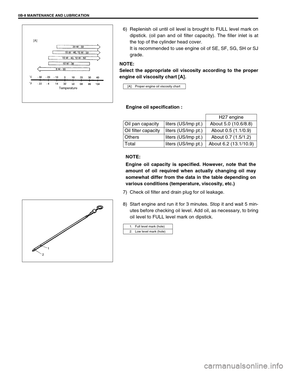
Select the appropriate oil viscosity according to the proper
engine oil viscosity chart [A].
Engine oil specification :
7) Check oil filter and drain plug for oil leakage.
8) Start engine and run it for 3 minutes. Stop it and wait 5 min-
utes before checking oil level. Add oil, as necessary, to bring
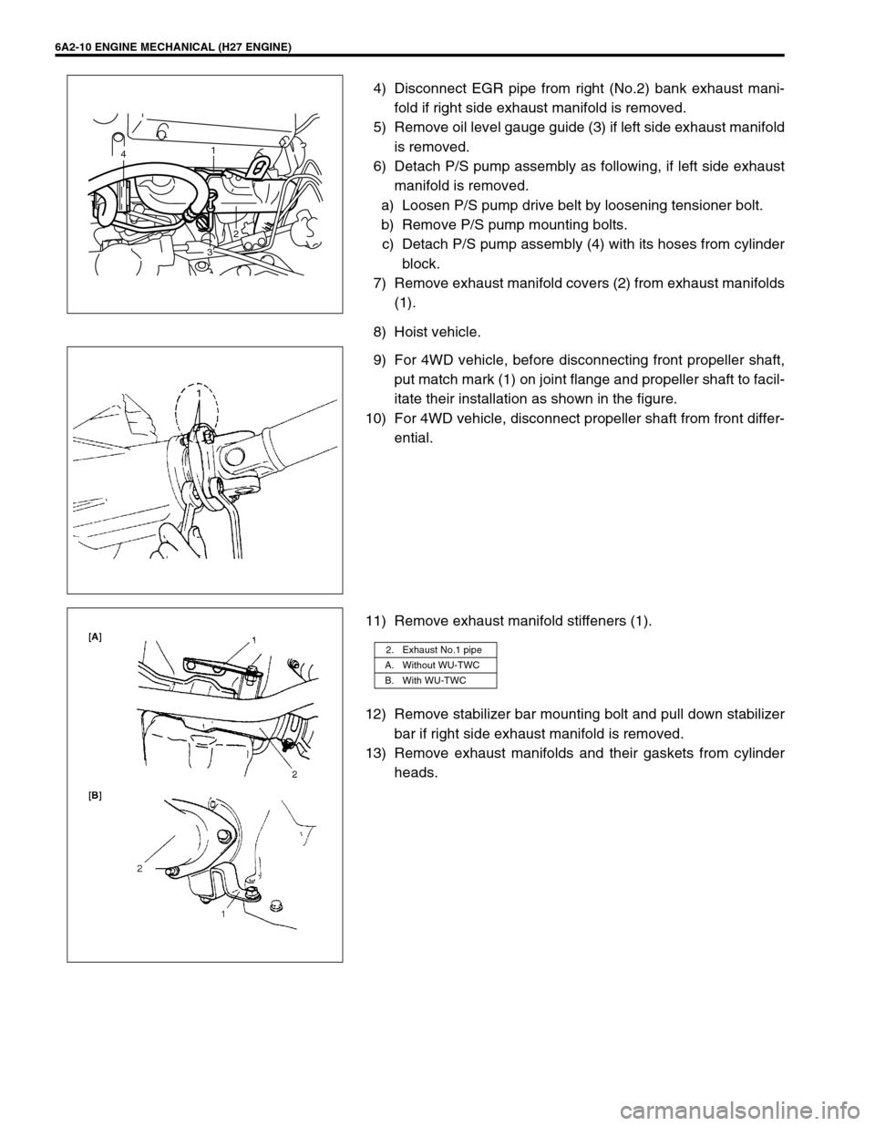
oil level to FULL level mark on dipstick.
[A]: Proper engine oil viscosity chart
H27 engine
Oil pan capacity liters (US/lmp pt.) About 5.0 (10.6/8.8)
Oil filter capacity liters (US/lmp pt.) About 0.5 (1.1/0.9)
Others liters (US/lmp pt.) About 0.7 (1.5/1.2)
Total liters (US/lmp pt.) About 6.2 (13.1/10.9)
NOTE:
Engine oil capacity is specified. However, note that the
amount of oil required when actually changing oil may
somewhat differ from the data in the table depending on
various conditions (temperature, viscosity, etc.)
1. Full level mark (hole)
2. Low level mark (hole)
Page 192 of 656

ENGINE GENERAL INFORMATION AND DIAGNOSIS (H27 ENGINE) 6-1-31
Engine Diagnosis Table
Perform troubleshooting referring to following table when ECM (PCM) has detected no DTC and no abnormality
has been found in visual inspection and engine basic inspection previously.
Condition Possible Cause Correction
Hard starting
(Engine cranks OK)Faulty idle air control system “DIAG. FLOW TABLE B-4” in this
section.
Faulty ECT sensor or MAF sensor ECT sensor or MAF sensor in Sec-
tion 6E2.
Faulty ECM (PCM) Inspection of ECM (PCM) and its
circuit in this section.
Low compression Compression check in Section
6A2.
Faulty hydraulic valve lash adjuster Valve lash adjuster in Section 6A2.
Compression leak from valve seat Valves inspection in Section 6A2.
Sticky valve stem Valves inspection in Section 6A2.
Weak or damaged valve springs Valves spring inspection in Section
6A2.
Compression leak at cylinder head gasket Cylinder head inspection in Section
6A2.
Sticking or damaged piston ring Piston ring inspection in Section
6A2.
Worn piston, ring or cylinder Cylinders, pistons and piston rings
inspection in Section 6A2.
Malfunctioning PCV valve PCV system inspection in Section
6E2.
Engine has no power
Engine overheating Refer to “OVERHEATING” in this
table.
Defective spark plug Spark plugs in Section 6F2.
Faulty ignition coil with ignitor Ignition coil in Section 6F2.
Fuel pressure out of specification
(dirty fuel filter, dirty or clogged fuel hose or
pipe, malfunctioning fuel pressure regulator,
malfunctioning fuel pump)“DIAG. FLOW TABLE B-3” in this
section.
Maladjusted TP sensor installation angle TP sensor in Section 6E2.
Faulty EGR system “DTC P0400 DIAG. FLOW TABLE”
in this section.
Faulty injector Fuel injector in Section 6E2.
Faulty TP sensor, ECT sensor or MAF sensor TP sensor, ECT sensor or MAF
sensor in Section 6E2.
Faulty ECM (PCM) Inspection of ECM (PCM) and its
circuit in this section.
Low compression Refer to the same item in “HARD
STARTING” of this table.
Dragging brakes Diagnosis in Section 5.
Slipping clutch Diagnosis in Section 7C1.
Page 194 of 656

ENGINE GENERAL INFORMATION AND DIAGNOSIS (H27 ENGINE) 6-1-33
Surges
(Engine power varia-
tion under steady
throttle or cruise.
Feels like the vehicle
speeds up and down
with no change in the
accelerator pedal.)Defective spark plug
(excess carbon deposits, improper gap, and
burned electrodes, etc.)Spark plugs in Section 6F2.
Variable fuel pressure
(clogged fuel filter, kinky or damaged fuel hose
and line, faulty fuel pressure regulator)“DIAG. FLOW TABLE B-3” in this
section.
Faulty EGR system “DTC P0400 DIAG. FLOW TABLE”
in this section.
Faulty MAF sensor MAF sensor in Section 6E2.
Faulty injector Fuel injector in Section 6E2.
Faulty ECM (PCM) Inspection of ECM (PCM) and its
circuit in this section.
Excessive detonation
(The engine makes
sharp metallic knocks
that change with throt-
tle opening. Sounds
like pop corn pop-
ping.)Engine overheating Refer to “OVERHEATING” in this
table.
Faulty spark plug Spark plugs in Section 6F2.
Improper ignition timing Ignition timing in Section 6F2.
Clogged fuel filter and fuel lines Fuel pressure check in Section
6E2.
Faulty EGR system “DTC P0400 DIAG. FLOW TABLE”
in this section.
Faulty ECT sensor or MAF sensor ECT sensor or MAF sensor in Sec-
tion 6E2.
Faulty injector Fuel injector in Section 6E2.
Faulty ECM (PCM) Inspection of ECM (PCM) and its
circuit in this section.
Excessive carbon deposits in combustion
chamberPiston and cylinder head cleaning
in Section 6A2.
Poor knock sensor performance “DTC P0325 DIAG. FLOW TABLE”
in this section.
Overheating
Inoperative thermostat Thermostat in Section 6B.
Poor water pump performance Water pump in Section 6B.
Clogged or leaky radiator Radiator in Section 6B.
Improper engine oil grade Engine oil and oil filter change in
Section 0B.
Clogged oil filter or oil strainer Oil pressure check in Section 6A2.
Poor oil pump performance Oil pressure check in Section 6A2.
Dragging brakes Diagnosis in Section 5.
Slipping clutch Diagnosis in Section 7C1.
Blown cylinder head gasket Cylinder head inspection in Section
6A2. Condition Possible Cause Correction
Page 195 of 656

6-1-34 ENGINE GENERAL INFORMATION AND DIAGNOSIS (H27 ENGINE)
Poor gasoline mileage
Faulty spark plug (improper gap, heavy depos-
its, and burned electrodes, etc.)Spark plugs in Section 6F2.
Fuel pressure out of specification “DIAG. FLOW TABLE B-3” in this
section.
Faulty TP sensor, ECT sensor or MAF sensor TP sensor, ECT sensor or MAF
sensor in Section 6E2.
Faulty EGR system “DTC P0400 DIAG. FLOW TABLE”
in this section.
Faulty injector Fuel injector in Section 6E2.
Faulty ECM (PCM) Inspection of ECM (PCM) and its
circuit in this section.
Low compression Refer to the same item in “HARD
STARTING” of this table.
Poor valve seating Valves inspection in Section 6A2.
Dragging brakes Diagnosis in Section 5.
Slipping clutch Diagnosis in Section 7C1.
Thermostat out of order Thermostat in Section 6B.
Improper tire pressure Diagnosis in Section 3.
Excessive engine oil
consumptionSticky piston ring Piston cleaning in Section 6A2.
Worn piston and cylinder Cylinders, pistons and piston rings
inspection in Section 6A2.
Worn piston ring groove and ring Pistons and piston rings inspection
in Section 6A2.
Improper location of piston ring gap Pistons installation in Section 6A2.
Worn or damaged valve stem seal Valves and cylinder head in Sec-
tion 6A2.
Worn valve stem Valves inspection in Section 6A2.
Low oil pressure
Improper oil viscosity Engine oil and oil filter change in
Section 0B.
Malfunctioning oil pressure switch Oil pressure switch inspection in
Section 8.
Clogged oil strainer Oil pan and oil pump strainer clean-
ing in Section 6A2.
Functional deterioration of oil pump Oil pump in Section 6A2.
Worn oil pump relief valve Oil pump in Section 6A2.
Excessive clearance in various sliding parts “INSPECTION” for each parts in
Section 6A2. Condition Possible Cause Correction
Page 288 of 656

ENGINE MECHANICAL (H27 ENGINE) 6A2-1
6A2
SECTION 6A2
ENGINE MECHANICAL (H27 ENGINE)
CONTENTS
On-Vehicle Service........................................6A2-2
Throttle Body and Intake Manifold .............. 6A2-2
Exhaust Manifold ......................................... 6A2-9
LH (No.1) Bank 2nd Timing Chain
and Chain Tensioner ................................. 6A2-13
Camshaft and Valve Lash Adjuster ........... 6A2-14
Valves and Cylinder Heads ....................... 6A2-17
Piston, Piston Rings, Connecting Rodsand Cylinders ............................................ 6A2-21
Unit Repair Overhaul .................................. 6A2-26
Engine Assembly ...................................... 6A2-26
Main Bearings, Crankshaft
and Cylinder Block .................................... 6A2-30
Special Tool ................................................. 6A2-36
WARNING:
For vehicles equipped with Supplemental Restraint (Air Bag) System:
Service on and around the air bag system components or wiring must be performed only by an
authorized SUZUKI dealer. Refer to “Air Bag System Components and Wiring Location View” under
“General Description” in air bag system section in order to confirm whether you are performing ser-
vice on or near the air bag system components or wiring. Please observe all WARNINGS and “Ser-
vice Precautions” under “On-Vehicle Service” in air bag system section before performing service
on or around the air bag system components or wiring. Failure to follow WARNINGS could result in
unintentional activation of the system or could render the system inoperative. Either of these two
conditions may result in severe injury.
Technical service work must be started at least 90 seconds after the ignition switch is turned to the
“LOCK” position and the negative cable is disconnected from the battery. Otherwise, the system
may be activated by reserve energy in the Sensing and Diagnostic Module (SDM).
NOTE:
For the descriptions (items) not found in this section, refer to the same section of service manual
mentioned in the FOREWORD of this manual.
Whether following systems (parts) are used in the particular vehicle or not depends on specifica-
tions. Be sure to bear this in mind when performing service work.
–EGR valve
–Warm up three way catalytic converter
–Heated oxygen sensor(s)
–Three way catalytic converter
–CKP sensor
–MAP sensor
Page 291 of 656

6A2-4 ENGINE MECHANICAL (H27 ENGINE)
8) Disconnect accelerator cable (1) and A/T throttle cable (2)
(for A/T vehicle) from throttle body.
9) Disconnect water hoses (3) from throttle body.
10) Disconnect injector wire (1) coupler.
11) Disconnect brake booster hose (2) from intake manifold.
12) Disconnect couplers of TP sensor (1) and IAC valve (2).
13) Disconnect earth terminal (3) from intake collector.
14) Remove clamp bracket (4) from intake collector.
15) Disconnect couplers from manifold absolute pressure (MAP)
sensor, EVAP canister purge valve, earth terminal and EGR
valve.
16) Disconnect PCV hose from cylinder head cover.
Disconnect breather hoses from throttle body or cylinder
head cover.
17) Disconnect hoses of EVAP canister purge valve and heater.
18) Remove EGR pipe.
12
33
2
1
2
14
3
1. EVAP canister purge valve 6. PCV hose
2. EGR valve 7. Water hose
3. EGR pipe 8. Breather hose
4. EVAP canister purge valve hose 9. Earth terminal coupler
5. Heater hose
9
4
1 7
6
2
35
8
Page 293 of 656

6A2-6 ENGINE MECHANICAL (H27 ENGINE)
INSTALLATION
1) Install new intake manifold gaskets (1) to cylinder heads.
2) Install intake manifold (1).
Tighten bolts and nuts to specified torque.
Tightening torque
Intake manifold bolt and nut (a) :
23 N·m (2.3 kg-m, 16.5 lb-ft)
3) Install throttle body (2) to intake collector (1) with new throttle
body gasket.
Tighten bolts and nuts to specified torque.
Tightening torque
Throttle body bolt and nut (b) :
23 N·m (2.3 kg-m, 16.5 lb-ft)
4) Install EGR valve (1), EVAP canister purge valve (2), mani-
fold absolute pressure (MAP) sensor and each hoses to
intake collector and throttle body if removed.
Use new gasket, when installing IAC valve and EGR valve.
5) Install throttle body and intake collector assembly to intake
manifold with new intake collector gaskets.
1
(a)
(a)(a)
(a)
2 1
(b)
(b)
3. EVAP canister purge valve hose
2
1
3
Page 297 of 656

6A2-10 ENGINE MECHANICAL (H27 ENGINE)
4) Disconnect EGR pipe from right (No.2) bank exhaust mani-
fold if right side exhaust manifold is removed.
5) Remove oil level gauge guide (3) if left side exhaust manifold
is removed.
6) Detach P/S pump assembly as following, if left side exhaust
manifold is removed.
a) Loosen P/S pump drive belt by loosening tensioner bolt.
b) Remove P/S pump mounting bolts.
c) Detach P/S pump assembly (4) with its hoses from cylinder
block.
7) Remove exhaust manifold covers (2) from exhaust manifolds
(1).
8) Hoist vehicle.
9) For 4WD vehicle, before disconnecting front propeller shaft,
put match mark (1) on joint flange and propeller shaft to facil-
itate their installation as shown in the figure.
10) For 4WD vehicle, disconnect propeller shaft from front differ-
ential.
11) Remove exhaust manifold stiffeners (1).
12) Remove stabilizer bar mounting bolt and pull down stabilizer
bar if right side exhaust manifold is removed.
13) Remove exhaust manifolds and their gaskets from cylinder
heads.
1
4
32
2. Exhaust No.1 pipe
A. Without WU-TWC
B. With WU-TWC