1999 SUZUKI GRAND VITARA rack
[x] Cancel search: rackPage 8 of 656

GENERAL INFORMATION 0A-3
Servicing and handling
WARNING:
Many of service procedures require disconnection of
“AIR BAG” fuse and all air bag (inflator) module(s) from
initiator circuit to avoid an accidental deployment.
Driver and Passenger Air Bag (Inflator) Modules
For handling and storage of a live air bag (inflator)
module, select a place where the ambient temperature
below 65°C (150°F), without high humidity and away
from electric noise.
When carrying a live air bag (inflator) module, make
sure the bag opening is pointed away from you. In
case of an accidental deployment, the bag will then
deploy with minimal chance of injury. Never carry the
air bag (inflator) module by the wires or connector on
the underside of the module. When placing a live air
bag (inflator) module on a bench or other surface,
always face the bag up, away from the surface. As the
live passenger air bag (inflator) module must be placed
with its bag (trim cover) facing up, place it on the work-
bench with a slit or use the workbench vise to hold it
securely at its lower mounting bracket. This is neces-
sary so that a free space is provided to allow the air
bag to expand in the unlikely event of accidental
deployment. Otherwise, personal injury may result.
Never dispose of live (undeployed) air bag (inflator)
modules (driver and passenger). If disposal is neces-
sary, be sure to deploy them according to deployment
procedures described in SECTION 10B before dis-
posal.
The air bag (inflator) module immediately after deploy-
ment is very hot. Wait for at least half an hour to cool it
off before proceeding the work.
After an air bag (inflator) module has been deployed,
the surface of the air bag may contain a powdery resi-
due. This powder consists primarily of cornstarch
(used to lubricate the bag as it inflates) and by-prod-
ucts of the chemical reaction. As with many service
procedures, gloves and safety glasses should be
worn.
[A] : ALWAYS CARRY AIR BAG (INFLATOR) MODULE WITH TRIM COVER (AIR
BAG OPENING) AWAY FROM BODY.
[B] : ALWAYS PLACE AIR BAG (INFLATOR) MODULE ON WORKBENCH WITH
TRIM COVER (AIR BAG OPENING) UP, AWAY FROM LOOSE OBJECTS.
1. Slit on workbench
2. Lower mounting bracket
3. Workbench vise
Page 9 of 656
0A-4 GENERAL INFORMATION
WARNING:
SDM
During service procedures, be very careful when handling a Sensing and Diagnostic Module (SDM).
Never strike or jar the SDM.
Never power up the air bag system when the SDM is not rigidly attached to the vehicle. All SDM and
mounting bracket fasteners must be carefully torqued and the arrow must be pointing toward the
front of the vehicle to ensure proper operation of the air bag system.
The SDM could be activated when powered while not rigidly attached to the vehicle which could
cause deployment and result in personal injury.
WARNING:
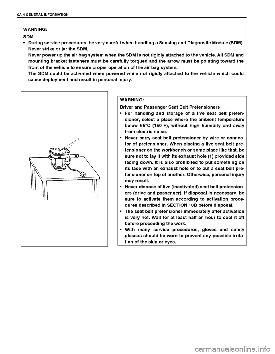
Driver and Passenger Seat Belt Pretensioners
For handling and storage of a live seat belt preten-
sioner, select a place where the ambient temperature
below 65°C (150°F), without high humidity and away
from electric noise.
Never carry seat belt pretensioner by wire or connec-
tor of pretensioner. When placing a live seat belt pre-
tensioner on the workbench or some place like that, be
sure not to lay it with its exhaust hole (1) provided side
facing down. It is also prohibited to put something on
its face with an exhaust hole or to put a seat belt pre-
tensioner on top of another. Otherwise, personal injury
may result.
Never dispose of live (inactivated) seat belt pretension-
ers (drive and passenger). If disposal is necessary, be
sure to activate them according to activation proce-
dures described in SECTION 10B before disposal.
The seat belt pretensioner immediately after activation
is very hot. Wait for at least half an hour to cool it off
before proceeding the work.
With many service procedures, gloves and safety
glasses should be worn to prevent any possible irrita-
tion of the skin or eyes.
Page 18 of 656

MAINTENANCE AND LUBRICATION 0B-5
Maintenance Service
Engine and Emission Control
ITEM 1-1
Drive belt inspection and replacement
WATER PUMP AND GENERATOR DRIVE BELT INSPEC-
TION
1) Disconnect negative (–) cable at battery.
2) Inspect belt for cracks, cuts, deformation, wear and cleanli-
ness. If any defect exists, replace.
Check belt for tension.
Water pump and generator belt tension “a”: 9-11 mm
(0.35- 0.43 in.) deflection under 100 N, 10 kg or 22 lb pres-
sure
3) If belt is too tight or too loose, adjust it to specification by
adjusting alternator position.
4) Tighten alternator adjusting bolt and pivot bolts.
5) Connect negative (–) cable to battery.
WATER PUMP AND GENERATOR DRIVE BELT REPLACE-
MENT
Replace belt. Refer to Section 6B for replacement procedure of
pump belt.WARNING:
All inspection and replacement are to be performed with
ENGINE NOT RUNNING.
NOTE:
When replacing belt with a new one, adjust belt tension
to 7 - 9 mm (0.28 - 0.35 in.)
1. Crankshaft pulley
2. Water pump pulley
3. 100 N, 10 kg or 22 lb
Page 19 of 656
0B-6 MAINTENANCE AND LUBRICATION
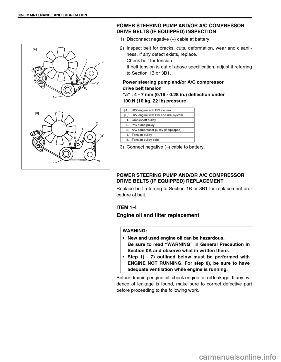
POWER STEERING PUMP AND/OR A/C COMPRESSOR
DRIVE BELTS (IF EQUIPPED) INSPECTION
1) Disconnect negative (–) cable at battery.
2) Inspect belt for cracks, cuts, deformation, wear and cleanli-
ness. If any defect exists, replace.
Check belt for tension.
If belt tension is out of above specification, adjust it referring
to Section 1B or 3B1.
Power steering pump and/or A/C compressor
drive belt tension
“a” : 4 - 7 mm (0.16 - 0.28 in.) deflection under
100 N (10 kg, 22 lb) pressure
3) Connect negative (–) cable to battery.
POWER STEERING PUMP AND/OR A/C COMPRESSOR
DRIVE BELTS (IF EQUIPPED) REPLACEMENT
Replace belt referring to Section 1B or 3B1 for replacement pro-
cedure of belt.
ITEM 1-4
Engine oil and filter replacement
Before draining engine oil, check engine for oil leakage. If any evi-
dence of leakage is found, make sure to correct defective part
before proceeding to the following work.
[A]: H27 engine with P/S system
[B]: H27 engine with P/S and A/C system
1. Crankshaft pulley
2. P/S pump pulley
3. A/C compressor pulley (if equipped)
4. Tension pulley
5. Tension pulley bolts
WARNING:
New and used engine oil can be hazardous.
Be sure to read “WARNING” in General Precaution in
Section 0A and observe what in written there.
Step 1) - 7) outlined below must be performed with
ENGINE NOT RUNNING. For step 8), be sure to have
adequate ventilation while engine is running.
Page 53 of 656
1B-28 AIR CONDITIONING (OPTIONAL)
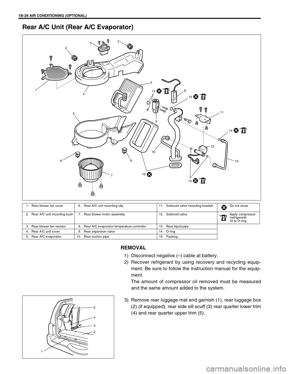
Rear A/C Unit (Rear A/C Evaporator)
REMOVAL
1) Disconnect negative (–) cable at battery.
2) Recover refrigerant by using recovery and recycling equip-
ment. Be sure to follow the instruction manual for the equip-
ment.
The amount of compressor oil removed must be measured
and the same amount added to the system.
3) Remove rear luggage mat end garnish (1), rear luggage box
(2) (if equipped), rear side sill scuff (3) rear quarter lower trim
(4) and rear quarter upper trim (5).
1. Rear blower fan cover 6. Rear A/C unit mounting clip 11. Solenoid valve mounting bracket Do not reuse
2. Rear A/C unit mounting bush 7. Rear blower motor assembly 12. Solenoid valve Apply compressor
(refrigerant)
oil to O-ring
3. Rear blower fan resistor 8. Rear A/C evaporator temperature controller 13. Rear liquid pipe
4. Rear A/C unit cover 9. Rear expansion valve 14. O-ring
5. Rear A/C evaporator 10. Rear suction pipe 15. Packing
6
7
15
10
14
12
13
14
14
14
11
8
9
4
6
5
41
232
5
4
3
2
1
Page 55 of 656
1B-30 AIR CONDITIONING (OPTIONAL)
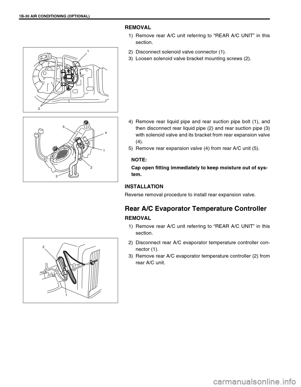
REMOVAL
1) Remove rear A/C unit referring to “REAR A/C UNIT” in this
section.
2) Disconnect solenoid valve connector (1).
3) Loosen solenoid valve bracket mounting screws (2).
4) Remove rear liquid pipe and rear suction pipe bolt (1), and
then disconnect rear liquid pipe (2) and rear suction pipe (3)
with solenoid valve and its bracket from rear expansion valve
(4).
5) Remove rear expansion valve (4) from rear A/C unit (5).
INSTALLATION
Reverse removal procedure to install rear expansion valve.
Rear A/C Evaporator Temperature Controller
REMOVAL
1) Remove rear A/C unit referring to “REAR A/C UNIT” in this
section.
2) Disconnect rear A/C evaporator temperature controller con-
nector (1).
3) Remove rear A/C evaporator temperature controller (2) from
rear A/C unit.
21
NOTE:
Cap open fitting immediately to keep moisture out of sys-
tem.
4
1
2
3
5
1 2
Page 57 of 656
1B-32 AIR CONDITIONING (OPTIONAL)
Solenoid Valve
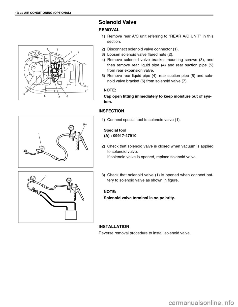
REMOVAL
1) Remove rear A/C unit referring to “REAR A/C UNIT” in this
section.
2) Disconnect solenoid valve connector (1).
3) Loosen solenoid valve flared nuts (2).
4) Remove solenoid valve bracket mounting screws (3), and
then remove rear liquid pipe (4) and rear suction pipe (5)
from rear expansion valve.
5) Remove rear liquid pipe (4), rear suction pipe (5) and sole-
noid valve bracket (6) from solenoid valve (7).
INSPECTION
1) Connect special tool to solenoid valve (1).
Special tool
(A) : 09917-47910
2) Check that solenoid valve is closed when vacuum is applied
to solenoid valve.
If solenoid valve is opened, replace solenoid valve.
3) Check that solenoid valve (1) is opened when connect bat-
tery to solenoid valve as shown in figure.
INSTALLATION
Reverse removal procedure to install solenoid valve.NOTE:
Cap open fitting immediately to keep moisture out of sys-
tem.
2
5
367 1 3 4
1(A)
NOTE:
Solenoid valve terminal is no polarity.
1
Page 61 of 656
1B-36 AIR CONDITIONING (OPTIONAL)
Rear Blower Motor Switch
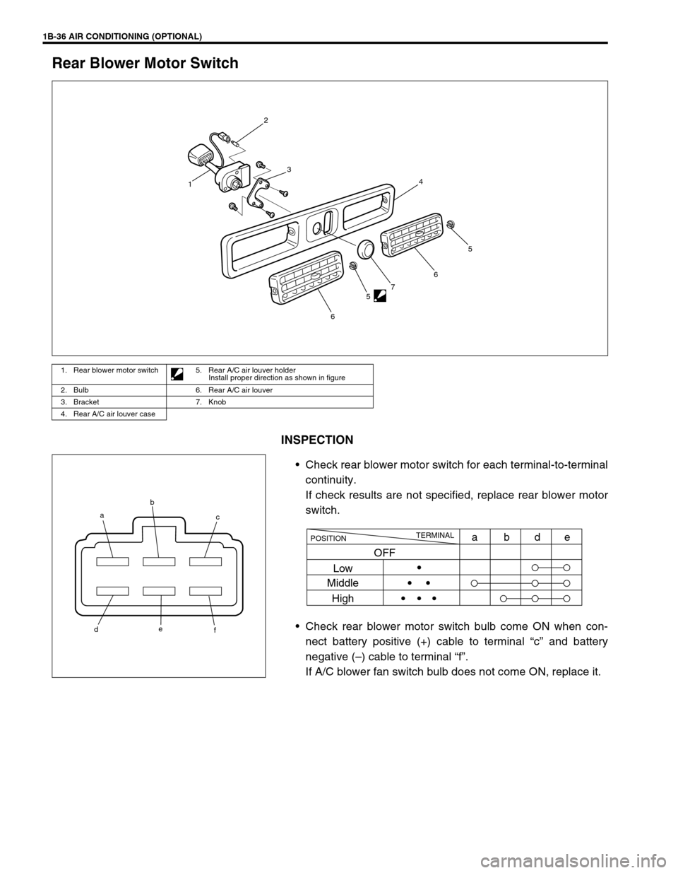
INSPECTION
Check rear blower motor switch for each terminal-to-terminal
continuity.
If check results are not specified, replace rear blower motor
switch.
Check rear blower motor switch bulb come ON when con-
nect battery positive (+) cable to terminal “c” and battery
negative (–) cable to terminal “f”.
If A/C blower fan switch bulb does not come ON, replace it.
1. Rear blower motor switch 5. Rear A/C air louver holder
Install proper direction as shown in figure
2. Bulb 6. Rear A/C air louver
3. Bracket 7. Knob
4. Rear A/C air louver case
2
13
4
66
7
55
ab
f e
dc
TERMINAL
POSITION
Low
Middle
Highabde
OFF