1999 SUZUKI GRAND VITARA section 6E2
[x] Cancel search: section 6E2Page 374 of 656

ENGINE AND EMISSION CONTROL SYSTEM (SEQUENTIAL MULTIPORT FUEL INJECTION FOR H27 ENGINE) 6E2-41
INSTALLATION
1) Confirm that vacuum passage on intake manifold is free from
clog.
2) Apply engine oil to O-ring of sensor.
3) Install sensor (1) to intake manifold (2).
4) Connect connector to sensor (1) securely.
Fuel level sensor (sender gauge)
Refer to Section 8C.
Crankshaft position sensor
REMOVAL AND INSTALLATION
Refer to Section 6A4.
INSPECTION
Refer to Section 6-1.
Main relay
INSPECTION
1) Disconnect negative (–) cable at battery.
2) Remove main relay (1) from its connector.
2. Fuel pump relay
3. Fuse box
4. Instrument panel
[A]: Left-hand steering vehicle
[B]: Right-hand steering vehicle
Page 385 of 656

6F2-2 IGNITION SYSTEM (FOR H27 ENGINE)
General Description
The ignition system is a direct ignition system. It consists of the parts as described below and has an electronic
ignition control system.
•ECM (or PCM)
It detects the engine condition through the signals from the sensors, determines the most suitable ignition
timing and time for electricity to flow to the primary coil and sends a signal to the igniter (in ignition coil
assembly).
•Ignition coil assembly (including an igniter and an ignition coil)
The ignition coil assembly has a built-in igniter and ignition coil which turns ON and OFF the primary current
of the ignition coil according to the signal from ECM (or PCM). When the ignition coil primary current is
turned OFF, a high voltage is induced in the secondary wiring. One ignition coil is in charge of ignition of one
cylinder only.
•Spark plug and noise suppressor
•CMP sensor, TP sensor, ECT sensor, IAT sensor, VSS, knock sensor and MAF sensor
For their details, refer to Section 6E2.
This ignition system does not have a distributor and high-tension cords but each cylinder has an ignition coil
assembly (igniter and ignition coil) and the secondary voltage which occurred in the ignition coil is sent to the
spark plug directly. Also, the signal(s) are sent from the CMP sensor to ECM (or PCM) so as to control each igni-
tion coil independently through the igniter (in ignition coil assembly).
Components
NOTE:
For other components not found in this figure, refer to Section 6E2.
1. Ignition coil assembly (igniter and ignition coil)
2. CMP sensor
3. Noise suppressor
4. ECM (or PCM)
5. Spark plug
Page 386 of 656

IGNITION SYSTEM (FOR H27 ENGINE) 6F2-3
System Wiring
NOTE:
For ECM (PCM) terminal assignment, refer to Section 6E2.
1. To ignition switch 8. Ignition coil assembly (For No.3 cylinder)
2.“IG COIL METER” fuse 9. Ignition coil assembly (For No.4 cylinder)
3. ECM (or PCM) 10. Spark plug
4. CMP sensor 11. Ignition coil assembly (For No.5 cylinder)
5. Noise suppressor 12. Ignition coil assembly (For No.6 cylinder)
6. Ignition coil assembly (For No.1 cylinder) 13. To main relay
7. Ignition coil assembly (For No.2 cylinder) 14. Sensed information
Page 387 of 656

6F2-4 IGNITION SYSTEM (FOR H27 ENGINE)
Diagnosis
Diagnostic Flow Table
Condition Possible Cause Correction
Engine cranks, but will
not start or hard to
start (No spark)Blown fuse for ignition coil assembly Replace.
Loose connection or disconnection of lead wire Connect securely.
Faulty spark plug (s) Replace.
Faulty ignition coil assembly (s) Replace.
Faulty CMP sensor Replace.
Faulty ECM (or PCM) Replace.
Maladjusted ignition timing Adjust.
Poor fuel economy or
engine performanceIncorrect ignition timing Adjust.
Faulty spark plug(s) Replace.
Faulty ignition coil assembly (s) Replace.
Faulty CMP sensor Replace.
Faulty ECM (or PCM) Replace.
Faulty knock sensor Replace.
Step Action Yes No
1Was “ENGINE DIAGNOSTIC FLOW TABLE” in
Section 6-1 performed?Go to Step 2. Go to “ENGINE DIAG-
NOSTIC FLOW TABLE” in
Section 6-1.
2 Ignition Spark Test
1) Check all spark plug for condition and type,
referring to “SPARK PLUG” in this section.
2) If OK, perform ignition spark test, referring
to “IGNITION SPARK CHECK” in this sec-
tion.
Is spark emitted from all spark plugs?Go to Step 8. Go to Step 3.
3 Diagnostic Trouble Code (DTC) Check
1) Check DTC stored in ECM (or PCM), refer-
ring to “DIAGNOSTIC TROUBLE CODE
(DTC) CHECK” in Section 6E2.
Is DTC stored?Go to applicable flow table
corresponding to that
code No. in Section 6E2.Go to Step 4.
4 Electrical Connection Check
1) Check ignition coil assemblies for electrical
connection.
Are they connected securely?Go to Step 5. Connect securely.
5 Ignition Coil Assembly Power Supply, Ground
and Trigger Signal Circuits Check
1) Check these circuits for open and short.
Are circuits in good condition?Go to Step 6. Repair or replace.
6 Ignition Coil Assembly Check
1) Substitute a known-good ignition coil
assembly and then repeat Step 2.
Is check result of Step 2 satisfactory?Malfunction of ignition coil
assembly.Go to Step 7.
Page 389 of 656

6F2-6 IGNITION SYSTEM (FOR H27 ENGINE)
Ignition Spark Check
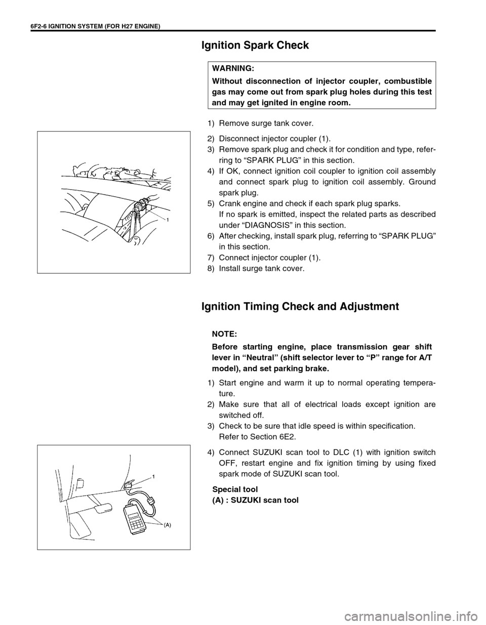
1) Remove surge tank cover.
2) Disconnect injector coupler (1).
3) Remove spark plug and check it for condition and type, refer-
ring to “SPARK PLUG” in this section.
4) If OK, connect ignition coil coupler to ignition coil assembly
and connect spark plug to ignition coil assembly. Ground
spark plug.
5) Crank engine and check if each spark plug sparks.
If no spark is emitted, inspect the related parts as described
under “DIAGNOSIS” in this section.
6) After checking, install spark plug, referring to “SPARK PLUG”
in this section.
7) Connect injector coupler (1).
8) Install surge tank cover.
Ignition Timing Check and Adjustment
1) Start engine and warm it up to normal operating tempera-
ture.
2) Make sure that all of electrical loads except ignition are
switched off.
3) Check to be sure that idle speed is within specification.
Refer to Section 6E2.
4) Connect SUZUKI scan tool to DLC (1) with ignition switch
OFF, restart engine and fix ignition timing by using fixed
spark mode of SUZUKI scan tool.
Special tool
(A) : SUZUKI scan tool WARNING:
Without disconnection of injector coupler, combustible
gas may come out from spark plug holes during this test
and may get ignited in engine room.
NOTE:
Before starting engine, place transmission gear shift
lever in “Neutral” (shift selector lever to “P” range for A/T
model), and set parking brake.
Page 423 of 656

7B1-14 AUTOMATIC TRANSMISSION (4 A/T)
Diagnostic Trouble Code Table
Refer to the same item in Section 6-1.
Fail Safe Table
Refer to the same item in Section 6-1.
Visual Inspection
Visually check following parts and systems.
A/T Basic Check
This inspection is important for troubleshooting when PCM (ECM) has detected no DTC and no abnormality has
been noted in visual inspection. Follow flow table carefully.INSPECTION ITEM REFERRING SECTION
•A/T fluid - - - - - level, leakage, color SECTION 0B
•A/T fluid hoses - - - - - disconnection, looseness, deterioration SECTION 7B1
•Throttle (accelerator) cable - - - - - play, installation SECTION 6E2
•A/T throttle cable - - - - - play, installation SECTION 7B1
•A/T select cable - - - - - installation, operation SECTION 7B1
•Engine oil - - - - - level, leakage SECTION 0B
•Engine coolant - - - - - level, leakage SECTION 0B
•Battery - - - - - fluid level, corrosion of terminal
•Connectors of electric wire harness - - - - - disconnection, friction Section 6-1 or 7B1
•Fuses - - - - - burning SECTION 8
•Parts - - - - - installation, damage
•bolt - - - - - looseness
•Other parts that can be checked visually
•Also check following items at engine start, if possible.
–“O/D OFF” lamp - - - - - Operation SECTION 7B1
–“POWER” lamp - - - - - Operation SECTION 7B1
–Malfunction indicator lamp (“SERVICE ENGINE SOON” lamp) - -
- - - OperationSection 6-1
–Charge warning lamp - - - - - Operation SECTION 6H
–Engine oil pressure warning lamp - - - - - Operation SECTION 8C (SECTION 6A2 for pres-
sure check)
–Engine coolant temp. meter - - - - - Operation
–Other parts that can be checked visually
Step Action Yes No
1Was “AUTOMATIC TRANSMISSION DIAGNOSTIC
FLOW TABLE” performed?Go to Step 2. Go to “AUTOMATIC
TRANSMISSION DIAG-
NOSTIC FLOW TABLE”.
2Perform “MANUAL ROAD TEST” in this section.
Is it OK?Go to Step 3. Go to Step 4.
3Proceed to “TROUBLE DIAGNOSIS TABLE 1” in this
section.
Is trouble identified?Repair or replace
defective parts.Go to Step 5.
Page 516 of 656

INSTRUMENTATION/DRIVER INFORMATION 8C-5
Engine Coolant Temperature (ECT) Meter and
Sensor
Engine coolant temperature sensor
REMOVAL AND INSTALLATION
Refer to “ECT SENSOR” in Section 6E2.
Oil Pressure Light
Oil pressure switch
REMOVAL AND INSTALLATION
Refer to “OIL PRESSURE CHECK” in Section 6A2.
Brake Warning Light
Brake fluid level switch
INSPECTION
Use an ohmmeter to check switch for continuity.
If found defective, replace switch (reservoir).
Brake fluid level switch specification
OFF position (float up) : No continuity
ON position (float down) : Continuity
Page 541 of 656

8E-20 CRUISE CONTROL SYSTEM
Coast/Set, Resume/Accel and Cancel
Switches
These switches are built in the combination switch assembly.
REMOVAL AND INSTALLATION
Refer to “COMBINATION SWITCH” in Section 3C1.
INSPECTION
1) Disable air bag system referring to “DISABLING AIR BAG
SYSTEM” in Section 10B.
2) Disconnect connector (1) of COAST/SET, RESUME/ACCEL
and CANCEL switches.
3) Check for resistance between “SW” and “GND” terminals of
disconnected switch connector (1) under each condition
below.
If check result is not satisfactory, replace combination switch
assembly.
COAST/SET, RESUME/ACCEL and CANSEL switch speci-
fication
All switches released (OFF) : Infinity
CANCEL switch pressed (ON) : About 0 Ω
ΩΩ Ω
COAST/SET switch rotated (ON) : 200 – 240 Ω
ΩΩ Ω
RESUME/ACCEL switch rotated (ON) : 820 – 1000 Ω
ΩΩ Ω
Vehicle Speed Sensor (VSS)
INSPECTION
Refer to Section 6E2.
Transmission Range Switch
Refer to Section 7B1 for inspection, removal, installation and
adjustment.CAUTION:
Never disassemble combination switch assembly. Disas-
sembly will spoil its original functions.