1999 SUZUKI GRAND VITARA fuel cap
[x] Cancel search: fuel capPage 56 of 656
AIR CONDITIONING (OPTIONAL) 1B-31
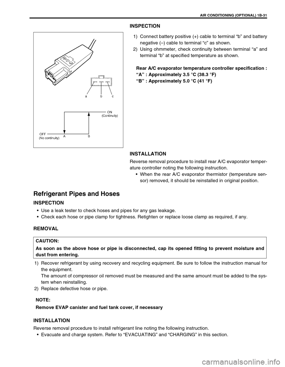
INSPECTION
1) Connect battery positive (+) cable to terminal “b” and battery
negative (–) cable to terminal “c” as shown.
2) Using ohmmeter, check continuity between terminal “a” and
terminal “b” at specified temperature as shown.
Rear A/C evaporator temperature controller specification :
“A” : Approximately 3.5 °C (38.3 °F)
“B” : Approximately 5.0 °C (41 °F)
INSTALLATION
Reverse removal procedure to install rear A/C evaporator temper-
ature controller noting the following instruction.
When the rear A/C evaporator thermistor (temperature sen-
sor) removed, it should be reinstalled in original position.
Refrigerant Pipes and Hoses
INSPECTION
Use a leak tester to check hoses and pipes for any gas leakage.
Check each hose or pipe clamp for tightness. Retighten or replace loose clamp as required, if any.
REMOVAL
1) Recover refrigerant by using recovery and recycling equipment. Be sure to follow the instruction manual for
the equipment.
The amount of compressor oil removed must be measured and the same amount must be added to the sys-
tem when reinstalling.
2) Replace defective hose or pipe.
INSTALLATION
Reverse removal procedure to install refrigerant line noting the following instruction.
Evacuate and charge system. Refer to “EVACUATING” and “CHARGING” in this section.
CAUTION:
As soon as the above hose or pipe is disconnected, cap its opened fitting to prevent moisture and
dust from entering.
NOTE:
Remove EVAP canister and fuel tank cover, if necessary
Page 166 of 656

ENGINE GENERAL INFORMATION AND DIAGNOSIS (H27 ENGINE) 6-1-5
Fuel Pressure Relief Procedure
After making sure that engine is cold, relief fuel pressure as fol-
lows.
1) Place transmission gear shift lever in “Neutral” (shift selector
lever to “P” range for A/T vehicle), set parking brake, and
block drive wheels.
2) Remove fuel pump relay (1) from its connector.
3) Remove fuel filler cap to release fuel vapor pressure in fuel
tank and then reinstall it.
4) Start engine and run it till it stops for lack of fuel. Repeat
cranking engine 2 – 3 times of about 3 seconds each time to
dissipate fuel pressure in lines. Fuel connections are now
safe for servicing.
5) Upon completion of servicing, install fuel pump relay to relay
box.
Fuel Leakage Check Procedure
After performing any service on fuel system, check to make sure
that there are no fuel leakages as follows.
1) Turn ON ignition switch for 3 seconds (to operate fuel pump)
and then turn it OFF.
Repeat this (ON and OFF) 3 or 4 times and apply fuel pres-
sure to fuel line (till fuel pressure is felt by hand placed on
fuel return hose).
2) In this state, check to see that there are no fuel leakages
from any part of fuel system. CAUTION:
This work must not be done when engine is hot. If done
so, it may cause adverse effect to catalyst.
[A] : Left hand steering vehicle
[B] : Right hand steering vehicle
2. Fuse box
Page 190 of 656

ENGINE GENERAL INFORMATION AND DIAGNOSIS (H27 ENGINE) 6-1-29
EGR VALVE (%)
This parameter indicates opening rate of EGR valve which controls the amount of EGR flow.
A/C SWITCH (ON/OFF)
ON : Command for operation being output from A/C amplifier to compressor.
OFF : Command for operation not being output.
PSP SWITCH (ON/OFF)
ON : PSP switch detects P/S operation. (high P/S pressure)
OFF : PSP switch not detects P/S operation.
PNP SIGNAL (Transmission Range Switch, P/N or D range)
Whether the transmission range switch (P/N position switch) at P or N range or at R, D, 2 or L range is displayed.
If at P or N range, “P/N range” is displayed and if at R, D, 2 or L range, “D range” is displayed.
FUEL TANK LEVEL (%)
This parameter indicates approximate fuel level in the fuel tank. As the detectable range of the fuel level sensor
is set as 0 to 100 %, however, with some models whose fuel tank capacity is smaller, the indicated fuel level may
be only 70 % even when the fuel tank is full.
ELECTRIC LOAD (ON/OFF)
ON : Small light switch ON or rear window defogger switch ON.
OFF : Small light switch OFF and rear window defogger switch OFF.
VSS (4-A/T) (km/h, MPH)
It is computed by using pulse signals from vehicle speed sensor on 4-speed automatic transmission.
THROT POS LEVEL (Throttle Position Level For 4-A/T, “0”, “1”, “2”, “3”, “4”,“5”,“6” or “7”)
This parameter indicates which level (zone) the throttle valve opening is in.
The throttle opening is divided into 8 levels (zones) from “0” (about idle position) to “7” (about full open) and sig-
nals are assigned to each opening level (zone). PCM controls the automatic gear change of the automatic trans-
mission by using these signals according to the signal from the TP sensor.
GEAR POSITION (1ST, 2ND, 3RD or 4TH)
The gear position is determined on the basis of the command state signals generated from PCM to shift sole-
noids A and B (#1 and #2) and displayed as shown in the table below.
SHIFT SOL #1 CON/MON (Shift Solenoid #1, A Command/monitor, ON/OFF)
CON-ON : ON command being output to shift solenoid #1, A.
CON-OFF : ON command not being output.
MON-ON : Electricity being passed to shift solenoid #1, A.
MON-OFF : Electricity not being passed.SHIFT SOLENOID-A SHIFT SOLENOID-B
DISPLAY1ST ON OFF
2ND ON ON
3RD OFF ON
4TH OFF OFF
Page 196 of 656
ENGINE GENERAL INFORMATION AND DIAGNOSIS (H27 ENGINE) 6-1-35
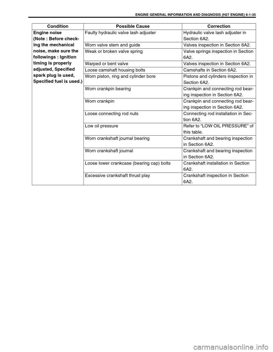
Engine noise
(Note : Before check-
ing the mechanical
noise, make sure the
followings : Ignition
timing is properly
adjusted, Specified
spark plug is used,
Specified fuel is used.)Faulty hydraulic valve lash adjuster Hydraulic valve lash adjuster in
Section 6A2.
Worn valve stem and guide Valves inspection in Section 6A2.
Weak or broken valve spring Valve springs inspection in Section
6A2.
Warped or bent valve Valves inspection in Section 6A2.
Loose camshaft housing bolts Camshafts in Section 6A2.
Worn piston, ring and cylinder bore Pistons and cylinders inspection in
Section 6A2.
Worn crankpin bearing Crankpin and connecting rod bear-
ing inspection in Section 6A2.
Worn crankpin Crankpin and connecting rod bear-
ing inspection in Section 6A2.
Loose connecting rod nuts Connecting rod installation in Sec-
tion 6A2.
Low oil pressure Refer to “LOW OIL PRESSURE” of
this table.
Worn crankshaft journal bearing Crankshaft and bearing inspection
in Section 6A2.
Worn crankshaft journal Crankshaft and bearing inspection
in Section 6A2.
Loose lower crankcase (bearing cap) bolts Crankshaft installation in Section
6A2.
Excessive crankshaft thrust play Crankshaft inspection in Section
6A2. Condition Possible Cause Correction
Page 277 of 656
6-1-116 ENGINE GENERAL INFORMATION AND DIAGNOSIS (H27 ENGINE)
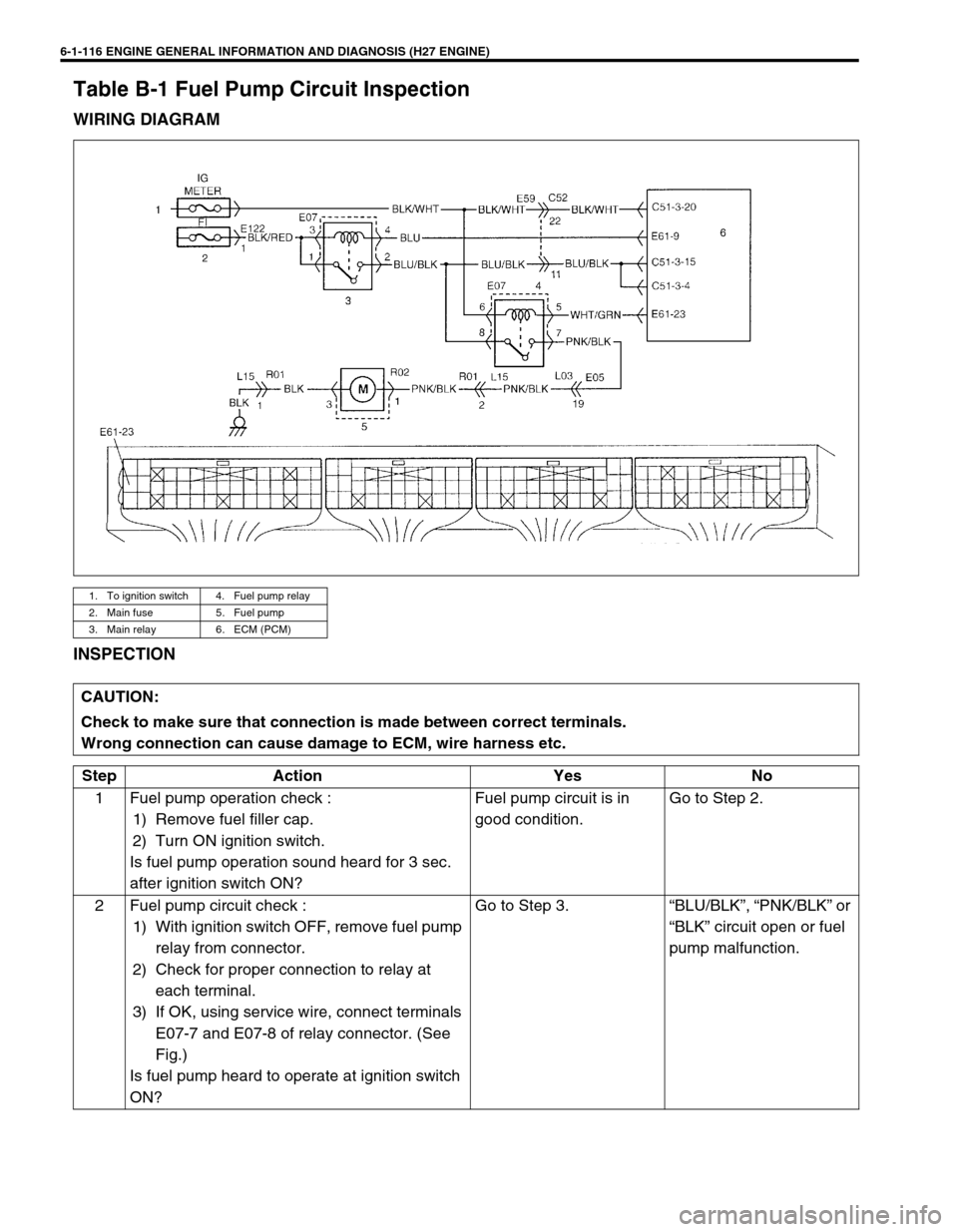
Table B-1 Fuel Pump Circuit Inspection
WIRING DIAGRAM
INSPECTION
1. To ignition switch 4. Fuel pump relay
2. Main fuse 5. Fuel pump
3. Main relay 6. ECM (PCM)
CAUTION:
Check to make sure that connection is made between correct terminals.
Wrong connection can cause damage to ECM, wire harness etc.
Step Action Yes No
1 Fuel pump operation check :
1) Remove fuel filler cap.
2) Turn ON ignition switch.
Is fuel pump operation sound heard for 3 sec.
after ignition switch ON?Fuel pump circuit is in
good condition.Go to Step 2.
2 Fuel pump circuit check :
1) With ignition switch OFF, remove fuel pump
relay from connector.
2) Check for proper connection to relay at
each terminal.
3) If OK, using service wire, connect terminals
E07-7 and E07-8 of relay connector. (See
Fig.)
Is fuel pump heard to operate at ignition switch
ON?Go to Step 3.“BLU/BLK”, “PNK/BLK” or
“BLK” circuit open or fuel
pump malfunction.
Page 290 of 656
ENGINE MECHANICAL (H27 ENGINE) 6A2-3
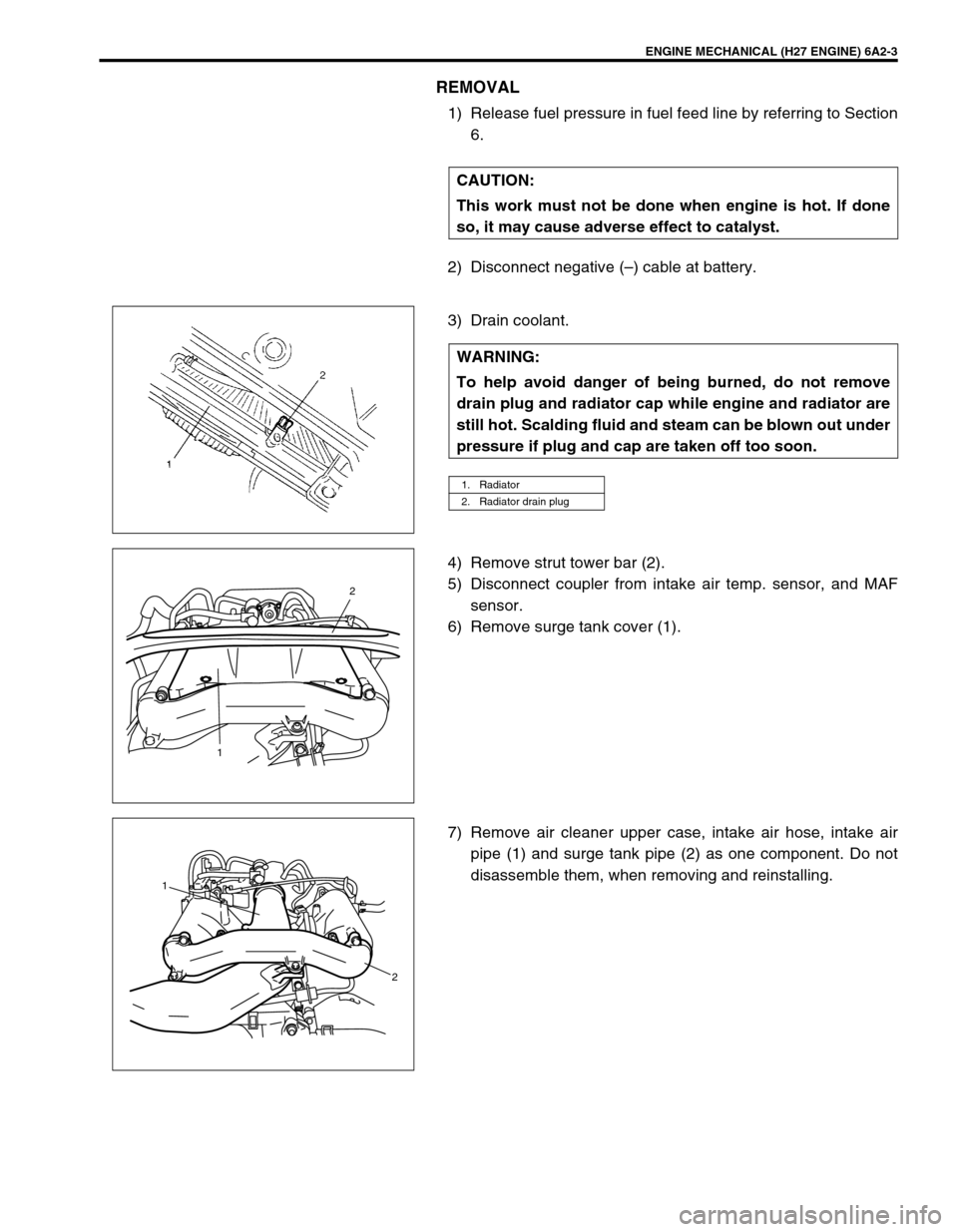
REMOVAL
1) Release fuel pressure in fuel feed line by referring to Section
6.
2) Disconnect negative (–) cable at battery.
3) Drain coolant.
4) Remove strut tower bar (2).
5) Disconnect coupler from intake air temp. sensor, and MAF
sensor.
6) Remove surge tank cover (1).
7) Remove air cleaner upper case, intake air hose, intake air
pipe (1) and surge tank pipe (2) as one component. Do not
disassemble them, when removing and reinstalling. CAUTION:
This work must not be done when engine is hot. If done
so, it may cause adverse effect to catalyst.
WARNING:
To help avoid danger of being burned, do not remove
drain plug and radiator cap while engine and radiator are
still hot. Scalding fluid and steam can be blown out under
pressure if plug and cap are taken off too soon.
1. Radiator
2. Radiator drain plug
2
1
1
2
Page 314 of 656

ENGINE MECHANICAL (H27 ENGINE) 6A2-27
12) Disconnect the following electric lead wires :
•Injector wire coupler
•CMP sensor coupler
•Ignition coil couplers
•CKP sensor coupler
•MAP sensor coupler
•TP sensor (1) coupler
•IAC valve (2) coupler
•Earth wire (3) from surge tank
•EVAP canister purge valve coupler
•EGR valve coupler
•Oxygen sensor -1 and -2 couplers referring to “Exhaust Man-
ifold” in this section
•Coolant temperature sensor coupler
•Knock sensor coupler
•Generator wires
•Starter wires
•Oil pressure wire
•P/S pump wire
•Earth wire from generator bracket
•Engine block heater (if equipped)
13) Remove clamps and brackets.
14) Disconnect the following hoses :
•Heater hose from heater water pipe
•Heater hose from water outlet cap
•EVAP canister hose from canister pipe
•Brake booster vacuum hose
15) Remove EVAP canister purge valve (5).
16) Disconnect the following hoses at the location shown in the
figure :
•Fuel feed hose (1) from fuel feed pipe
•Fuel return hose from (2) fuel return pipe
17) Remove P/S pump assembly. Refer to “POWER STEERING
PUMP” in Section 3B1.
18) Remove A/C compressor assembly. Refer to “COMPRES-
SOR ASSEMBLY” in Section 1B.
19) Remove steering shaft lower assembly. Refer to “STEERING
LOWER SHAFT ASSEMBLY” in Section 3C1.
20) Raise vehicle.
21) Remove front differential housing with differential from chas-
sis if equipped. Refer to “DISMOUNTING” in Section 7E.
22) Remove exhaust No.1 pipe. Refer to “EXHAUST MANI-
FOLD” in this section.
23) Remove exhaust manifold stiffener from transmission.
4. Clamp bracket
6. EGR valve
7. Heater hose
2
14
3
75
6
Page 328 of 656
ENGINE FUEL 6C-1
6C
SECTION 6C
ENGINE FUEL
CONTENTS
General Description ....................................... 6C-1
Fuel System ................................................. 6C-1On-Vehicle Service ........................................ 6C-2
Fuel Tank ..................................................... 6C-2
Fuel Lines .................................................... 6C-5
General Description
Fuel System
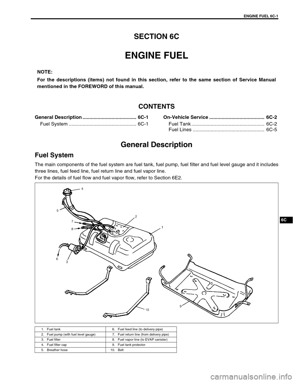
The main components of the fuel system are fuel tank, fuel pump, fuel filter and fuel level gauge and it includes
three lines, fuel feed line, fuel return line and fuel vapor line.
For the details of fuel flow and fuel vapor flow, refer to Section 6E2.NOTE:
For the descriptions (items) not found in this section, refer to the same section of Service Manual
mentioned in the FOREWORD of this manual.
1. Fuel tank 6. Fuel feed line (to delivery pipe)
2. Fuel pump (with fuel level gauge) 7. Fuel return line (from delivery pipe)
3. Fuel filter 8. Fuel vapor line (to EVAP canister)
4. Fuel filter cap 9. Fuel tank protector
5. Breather hose 10. Belt