Page 192 of 656

ENGINE GENERAL INFORMATION AND DIAGNOSIS (H27 ENGINE) 6-1-31
Engine Diagnosis Table
Perform troubleshooting referring to following table when ECM (PCM) has detected no DTC and no abnormality
has been found in visual inspection and engine basic inspection previously.
Condition Possible Cause Correction
Hard starting
(Engine cranks OK)Faulty idle air control system “DIAG. FLOW TABLE B-4” in this
section.
Faulty ECT sensor or MAF sensor ECT sensor or MAF sensor in Sec-
tion 6E2.
Faulty ECM (PCM) Inspection of ECM (PCM) and its
circuit in this section.
Low compression Compression check in Section
6A2.
Faulty hydraulic valve lash adjuster Valve lash adjuster in Section 6A2.
Compression leak from valve seat Valves inspection in Section 6A2.
Sticky valve stem Valves inspection in Section 6A2.
Weak or damaged valve springs Valves spring inspection in Section
6A2.
Compression leak at cylinder head gasket Cylinder head inspection in Section
6A2.
Sticking or damaged piston ring Piston ring inspection in Section
6A2.
Worn piston, ring or cylinder Cylinders, pistons and piston rings
inspection in Section 6A2.
Malfunctioning PCV valve PCV system inspection in Section
6E2.
Engine has no power
Engine overheating Refer to “OVERHEATING” in this
table.
Defective spark plug Spark plugs in Section 6F2.
Faulty ignition coil with ignitor Ignition coil in Section 6F2.
Fuel pressure out of specification
(dirty fuel filter, dirty or clogged fuel hose or
pipe, malfunctioning fuel pressure regulator,
malfunctioning fuel pump)“DIAG. FLOW TABLE B-3” in this
section.
Maladjusted TP sensor installation angle TP sensor in Section 6E2.
Faulty EGR system “DTC P0400 DIAG. FLOW TABLE”
in this section.
Faulty injector Fuel injector in Section 6E2.
Faulty TP sensor, ECT sensor or MAF sensor TP sensor, ECT sensor or MAF
sensor in Section 6E2.
Faulty ECM (PCM) Inspection of ECM (PCM) and its
circuit in this section.
Low compression Refer to the same item in “HARD
STARTING” of this table.
Dragging brakes Diagnosis in Section 5.
Slipping clutch Diagnosis in Section 7C1.
Page 193 of 656

6-1-32 ENGINE GENERAL INFORMATION AND DIAGNOSIS (H27 ENGINE)
Improper engine idling
or engine fails to idleFaulty spark plug Spark plugs in Section 6F2.
Faulty ignition coil with ignitor Ignition coil in Section 6F2.
Fuel pressure out of specification “DIAG. FLOW TABLE B-3” in this
section.
Engine overheating Refer to “OVERHEATING” in this
table.
Maladjusted TP sensor installation angle if
adjustableTP sensor in Section 6E2.
Faulty idle air control system “DIAG. FLOW TABLE B-4” in this
section.
Faulty FIA (fast idle air) valve FIA valve in Section 6E2.
Faulty evaporative emission control system EVAP control system in Section
6E2.
Faulty EGR system “DTC P0400 DIAG. FLOW TABLE”
in this section.
Faulty injector Fuel injection in Section 6E2.
Faulty ECT sensor, TP sensor or MAF sensor ECT sensor, TP sensor or MAF
sensor in Section 6E2.
Faulty ECM (PCM) Inspection of ECM (PCM) and its
circuit in this section.
Low compression Refer to the same item in “HARD
STARTING” of this table.
Malfunctioning PCV valve PCV system inspection in Section
6E2.
Engine hesitates
(Momentary lack of
response as the accel-
erator is depressed.
Can occur at all vehi-
cle speeds.
Usually most severe
when first trying to
make the vehicle
move, as from a stop
sign.)Spark plug faulty or plug gap as out of adjust-
mentSpark plugs in Section 6F2.
Fuel pressure out of specification
(clogged fuel filter, faulty fuel pressure regula-
tor, clogged fuel filter, hose or pipe)“DIAG. FLOW TABLE B-3” in this
section.
Engine overheating Refer to “OVERHEATING” in this
table.
Faulty EGR system “DTC P0400 DIAG. FLOW TABLE”
in this section.
Faulty injector Fuel injector in Section 6E2.
Faulty TP sensor, ECT sensor or MAF sensor TP sensor, ECT sensor or MAF
sensor in Section 6E2.
Faulty ECM (PCM) Inspection of ECM (PCM) and its
circuit in this section.
Low compression Refer to the same item in “HARD
STARTING” of this table. Condition Possible Cause Correction
Page 379 of 656

6E2-46 ENGINE AND EMISSION CONTROL SYSTEM (SEQUENTIAL MULTIPORT FUEL INJECTION FOR H27 ENGINE)
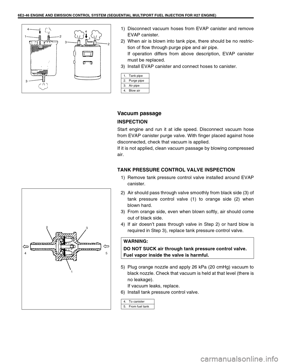
1) Disconnect vacuum hoses from EVAP canister and remove
EVAP canister.
2) When air is blown into tank pipe, there should be no restric-
tion of flow through purge pipe and air pipe.
If operation differs from above description, EVAP canister
must be replaced.
3) Install EVAP canister and connect hoses to canister.
Vacuum passage
INSPECTION
Start engine and run it at idle speed. Disconnect vacuum hose
from EVAP canister purge valve. With finger placed against hose
disconnected, check that vacuum is applied.
If it is not applied, clean vacuum passage by blowing compressed
air.
TANK PRESSURE CONTROL VALVE INSPECTION
1) Remove tank pressure control valve installed around EVAP
canister.
2) Air should pass through valve smoothly from black side (3) of
tank pressure control valve (1) to orange side (2) when
blown hard.
3) From orange side, even when blown softly, air should come
out of black side.
4) If air doesn’t pass through valve in Step 2) or hard blow is
required in Step 3), replace tank pressure control valve.
5) Plug orange nozzle and apply 26 kPa (20 cmHg) vacuum to
black nozzle. Check that vacuum is held at that level (there is
no leakage).
If vacuum leaks, replace.
6) Install tank pressure control valve.
1. Tank pipe
2. Purge pipe
3. Air pipe
4. Blow air
WARNING:
DO NOT SUCK air through tank pressure control valve.
Fuel vapor inside the valve is harmful.
4. To canister
5. From fuel tank