1999 SUZUKI GRAND VITARA Remove rear sit
[x] Cancel search: Remove rear sitPage 48 of 656
AIR CONDITIONING (OPTIONAL) 1B-23
The initial charging of the A/C system is performed from the high-
pressure side with the engine stopped.
And next, this method must be followed by charging from the low-
pressure side with the engine running.
1) Check to make sure that hoses are routed properly after
evacuating the system.
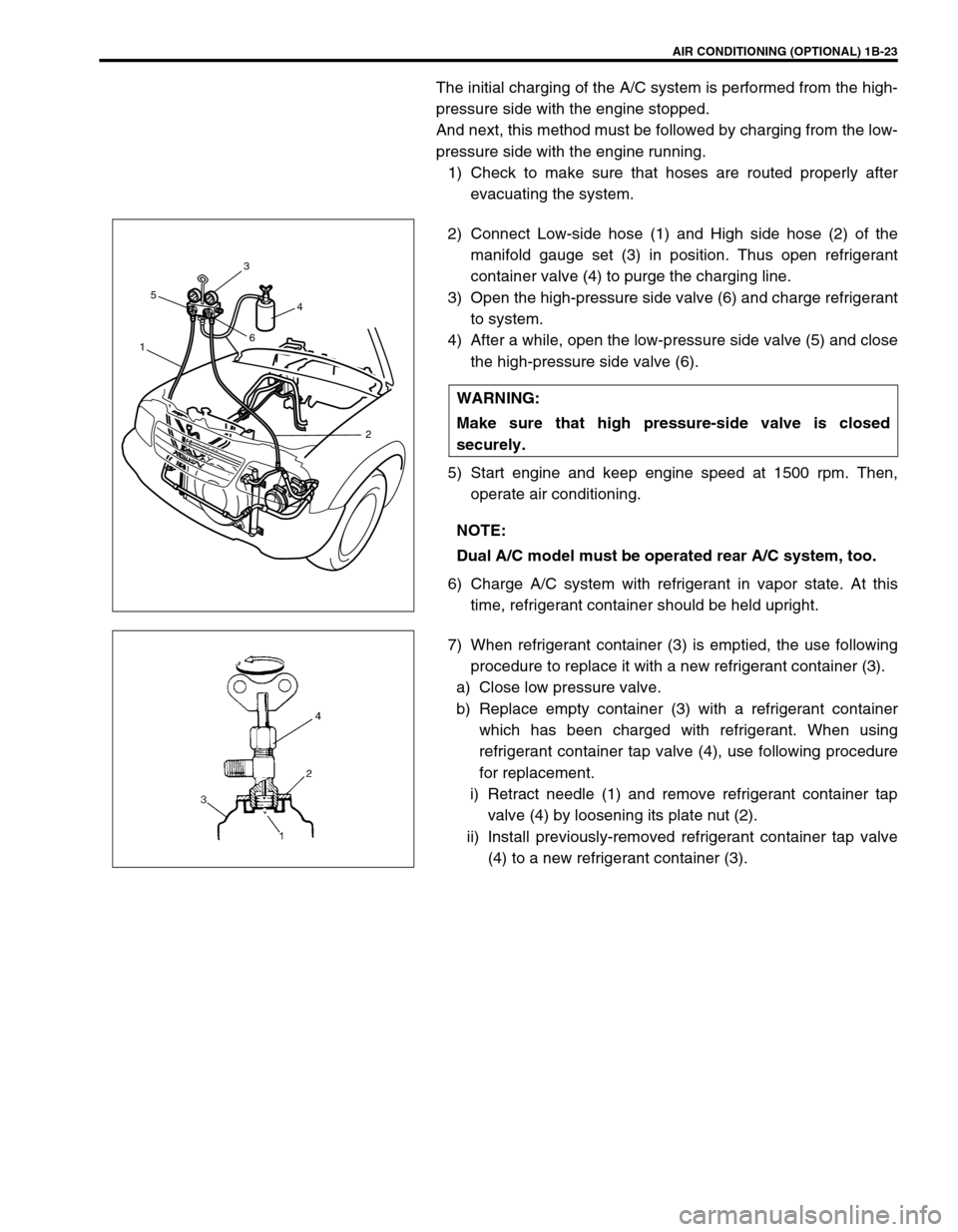
2) Connect Low-side hose (1) and High side hose (2) of the
manifold gauge set (3) in position. Thus open refrigerant
container valve (4) to purge the charging line.
3) Open the high-pressure side valve (6) and charge refrigerant
to system.
4) After a while, open the low-pressure side valve (5) and close
the high-pressure side valve (6).
5) Start engine and keep engine speed at 1500 rpm. Then,
operate air conditioning.
6) Charge A/C system with refrigerant in vapor state. At this
time, refrigerant container should be held upright.
7) When refrigerant container (3) is emptied, the use following
procedure to replace it with a new refrigerant container (3).
a) Close low pressure valve.
b) Replace empty container (3) with a refrigerant container
which has been charged with refrigerant. When using
refrigerant container tap valve (4), use following procedure
for replacement.
i) Retract needle (1) and remove refrigerant container tap
valve (4) by loosening its plate nut (2).
ii) Install previously-removed refrigerant container tap valve
(4) to a new refrigerant container (3). WARNING:
Make sure that high pressure-side valve is closed
securely.
NOTE:
Dual A/C model must be operated rear A/C system, too.
153
64
2
Page 54 of 656
AIR CONDITIONING (OPTIONAL) 1B-29
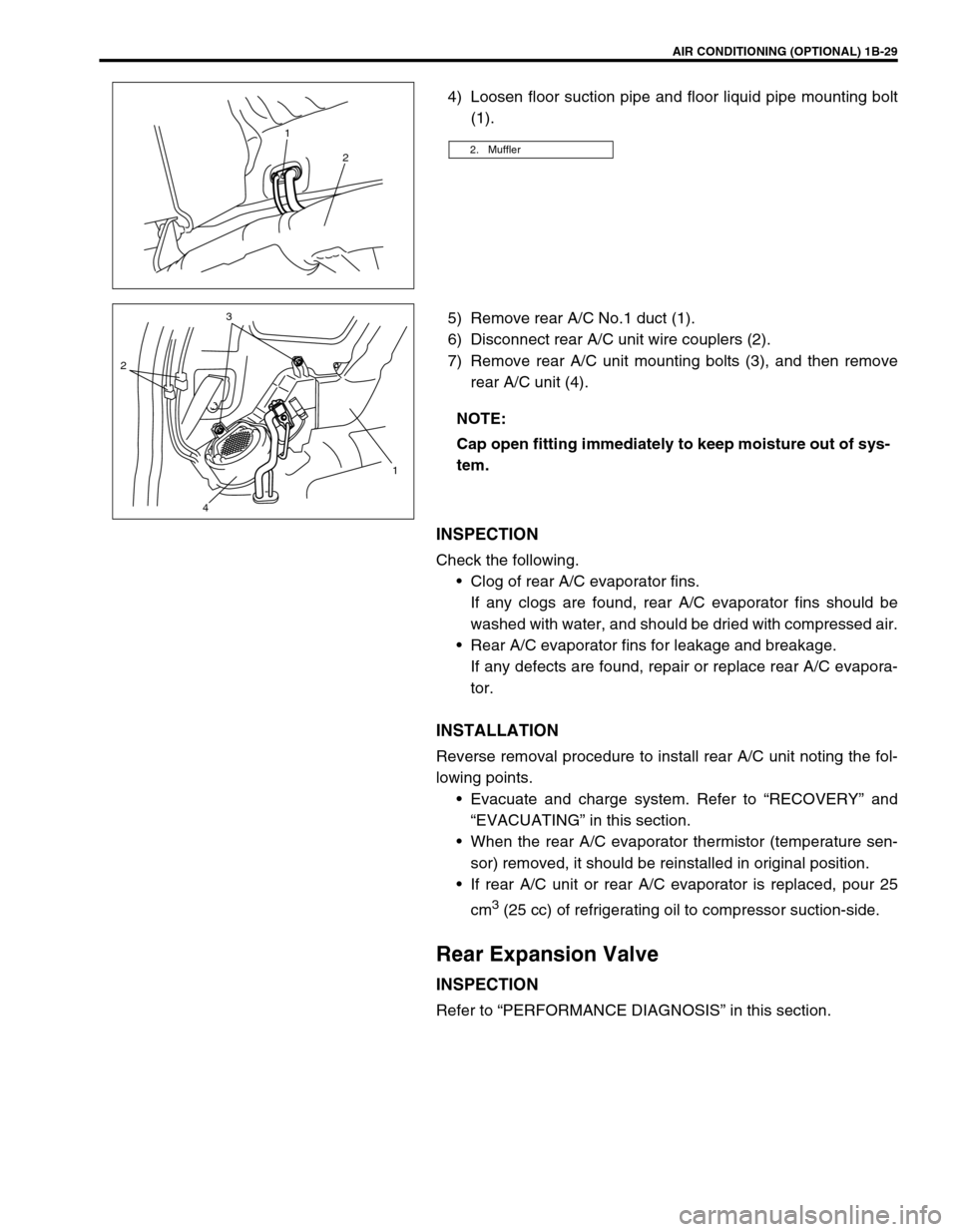
4) Loosen floor suction pipe and floor liquid pipe mounting bolt
(1).
5) Remove rear A/C No.1 duct (1).
6) Disconnect rear A/C unit wire couplers (2).
7) Remove rear A/C unit mounting bolts (3), and then remove
rear A/C unit (4).
INSPECTION
Check the following.
Clog of rear A/C evaporator fins.
If any clogs are found, rear A/C evaporator fins should be
washed with water, and should be dried with compressed air.
Rear A/C evaporator fins for leakage and breakage.
If any defects are found, repair or replace rear A/C evapora-
tor.
INSTALLATION
Reverse removal procedure to install rear A/C unit noting the fol-
lowing points.
Evacuate and charge system. Refer to “RECOVERY” and
“EVACUATING” in this section.
When the rear A/C evaporator thermistor (temperature sen-
sor) removed, it should be reinstalled in original position.
If rear A/C unit or rear A/C evaporator is replaced, pour 25
cm
3 (25 cc) of refrigerating oil to compressor suction-side.
Rear Expansion Valve
INSPECTION
Refer to “PERFORMANCE DIAGNOSIS” in this section.
2. Muffler
1
2
NOTE:
Cap open fitting immediately to keep moisture out of sys-
tem.
23
1
4
Page 56 of 656
AIR CONDITIONING (OPTIONAL) 1B-31
INSPECTION
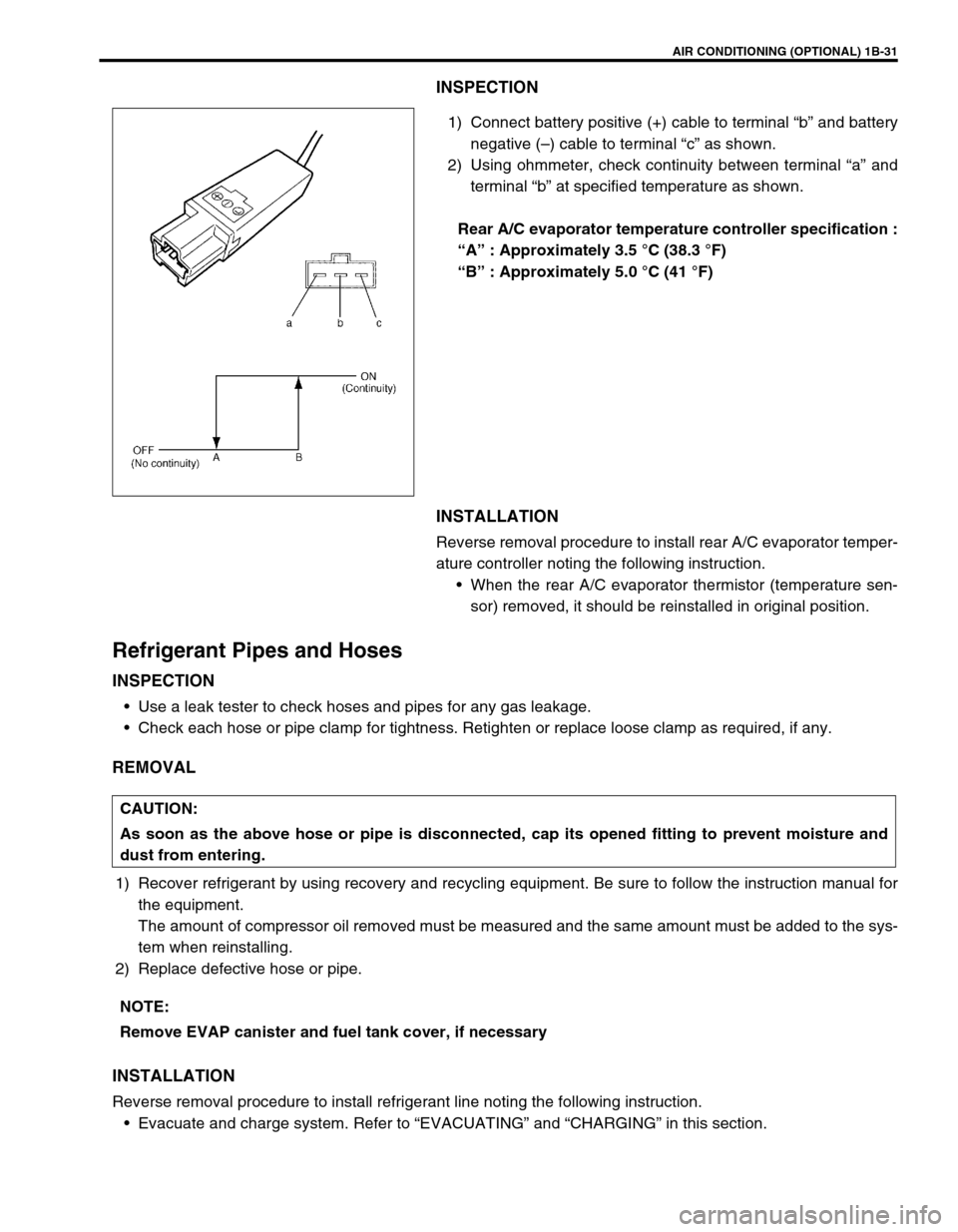
1) Connect battery positive (+) cable to terminal “b” and battery
negative (–) cable to terminal “c” as shown.
2) Using ohmmeter, check continuity between terminal “a” and
terminal “b” at specified temperature as shown.
Rear A/C evaporator temperature controller specification :
“A” : Approximately 3.5 °C (38.3 °F)
“B” : Approximately 5.0 °C (41 °F)
INSTALLATION
Reverse removal procedure to install rear A/C evaporator temper-
ature controller noting the following instruction.
When the rear A/C evaporator thermistor (temperature sen-
sor) removed, it should be reinstalled in original position.
Refrigerant Pipes and Hoses
INSPECTION
Use a leak tester to check hoses and pipes for any gas leakage.
Check each hose or pipe clamp for tightness. Retighten or replace loose clamp as required, if any.
REMOVAL
1) Recover refrigerant by using recovery and recycling equipment. Be sure to follow the instruction manual for
the equipment.
The amount of compressor oil removed must be measured and the same amount must be added to the sys-
tem when reinstalling.
2) Replace defective hose or pipe.
INSTALLATION
Reverse removal procedure to install refrigerant line noting the following instruction.
Evacuate and charge system. Refer to “EVACUATING” and “CHARGING” in this section.
CAUTION:
As soon as the above hose or pipe is disconnected, cap its opened fitting to prevent moisture and
dust from entering.
NOTE:
Remove EVAP canister and fuel tank cover, if necessary
Page 59 of 656
1B-34 AIR CONDITIONING (OPTIONAL)
Rear Blower Motor Relay and Solenoid Valve
Relay
INSPECTION
1) Disconnect negative (–) cable at battery.
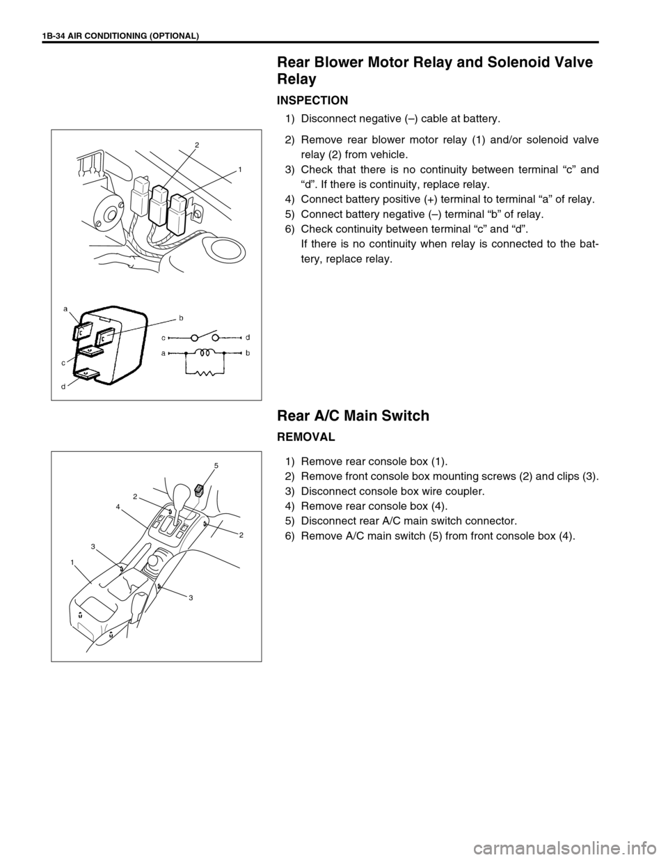
2) Remove rear blower motor relay (1) and/or solenoid valve
relay (2) from vehicle.
3) Check that there is no continuity between terminal “c” and
“d”. If there is continuity, replace relay.
4) Connect battery positive (+) terminal to terminal “a” of relay.
5) Connect battery negative (–) terminal “b” of relay.
6) Check continuity between terminal “c” and “d”.
If there is no continuity when relay is connected to the bat-
tery, replace relay.
Rear A/C Main Switch
REMOVAL
1) Remove rear console box (1).
2) Remove front console box mounting screws (2) and clips (3).
3) Disconnect console box wire coupler.
4) Remove rear console box (4).
5) Disconnect rear A/C main switch connector.
6) Remove A/C main switch (5) from front console box (4).
2
1
2
4
3
15
2
3
Page 60 of 656
AIR CONDITIONING (OPTIONAL) 1B-35
INSPECTION
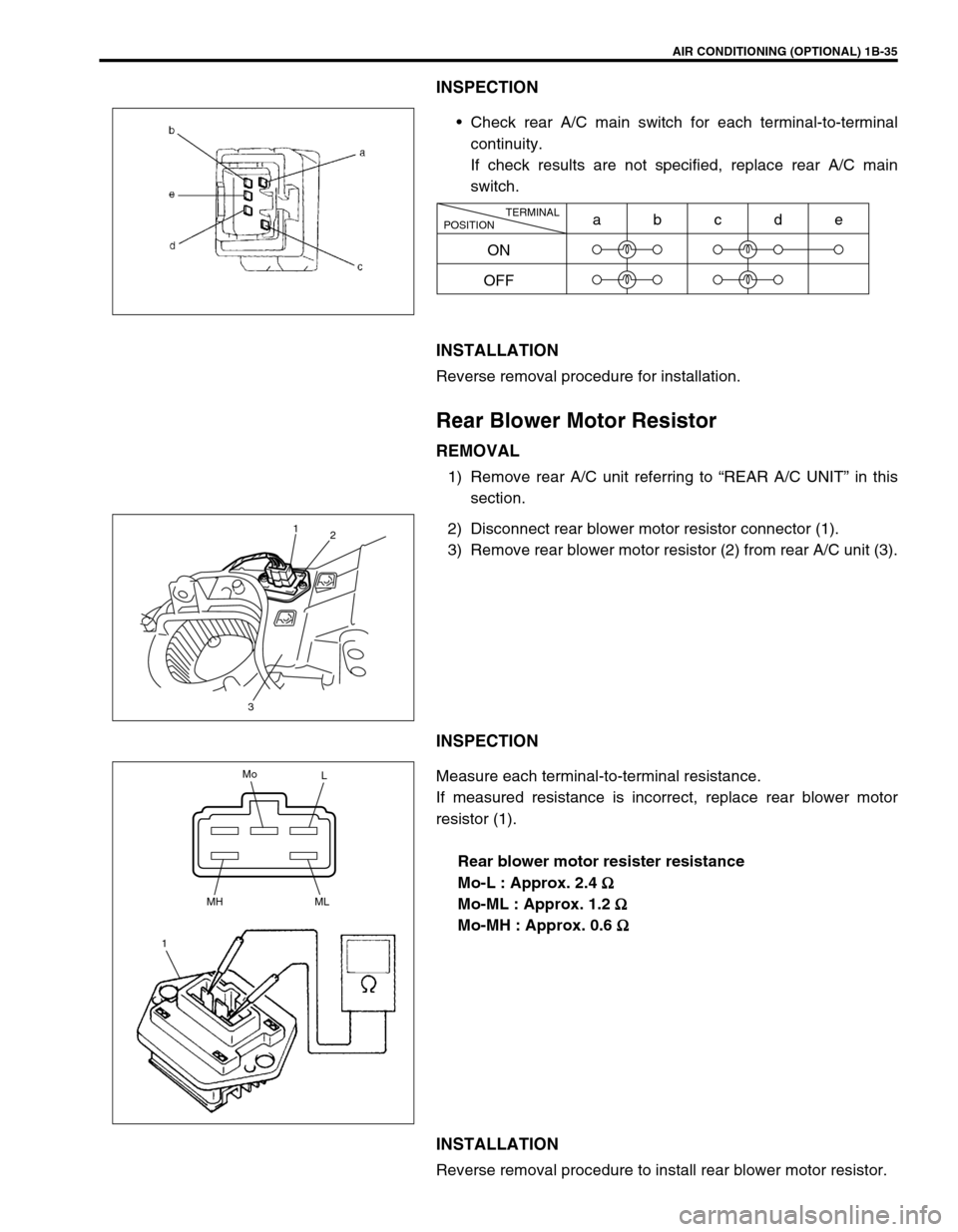
Check rear A/C main switch for each terminal-to-terminal
continuity.
If check results are not specified, replace rear A/C main
switch.
INSTALLATION
Reverse removal procedure for installation.
Rear Blower Motor Resistor
REMOVAL
1) Remove rear A/C unit referring to “REAR A/C UNIT” in this
section.
2) Disconnect rear blower motor resistor connector (1).
3) Remove rear blower motor resistor (2) from rear A/C unit (3).
INSPECTION
Measure each terminal-to-terminal resistance.
If measured resistance is incorrect, replace rear blower motor
resistor (1).
Rear blower motor resister resistance
Mo-L : Approx. 2.4
Ω
ΩΩ Ω
Mo-ML : Approx. 1.2
Ω
ΩΩ Ω
Mo-MH : Approx. 0.6
Ω
ΩΩ Ω
INSTALLATION
Reverse removal procedure to install rear blower motor resistor.
TERMINAL
POSITION
ON
OFFabcde
1
2
3
Mo
L
MH
1ML
Page 121 of 656
5C-4 PARKING AND REAR BRAKE
Cracked, scored, or grooved drum
A cracked, drum is unsafe for further service and must be
replaced.
Do not attempt to weld a cracked drum.
Smooth up any slight scores. Heavy or extensive scoring will
cause excessive brake lining wear and it will probably be neces-
sary to resurface drum braking surface.
If brake linings are slightly worn and drum is grooved, drum
should be polished with fine emery cloth but should no be turned.
Brake shoe
Where lining is worn out beyond service limit, replace shoe.
If one of brake linings is to service limit, all linings must be
replaced at the same time.
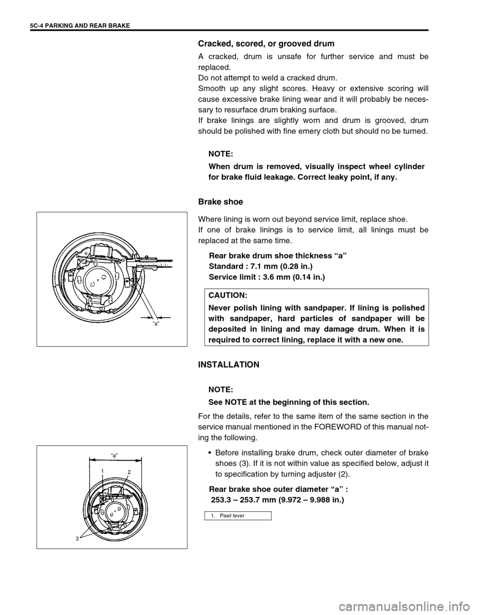
Rear brake drum shoe thickness “a”
Standard : 7.1 mm (0.28 in.)
Service limit : 3.6 mm (0.14 in.)
INSTALLATION
For the details, refer to the same item of the same section in the
service manual mentioned in the FOREWORD of this manual not-
ing the following.
Before installing brake drum, check outer diameter of brake
shoes (3). If it is not within value as specified below, adjust it
to specification by turning adjuster (2).
Rear brake shoe outer diameter “a” :
253.3 – 253.7 mm (9.972 – 9.988 in.) NOTE:
When drum is removed, visually inspect wheel cylinder
for brake fluid leakage. Correct leaky point, if any.
CAUTION:
Never polish lining with sandpaper. If lining is polished
with sandpaper, hard particles of sandpaper will be
deposited in lining and may damage drum. When it is
required to correct lining, replace it with a new one.
NOTE:
See NOTE at the beginning of this section.
1. Pawl lever
Page 481 of 656
7E-8 DIFFERENTIAL (FRONT)
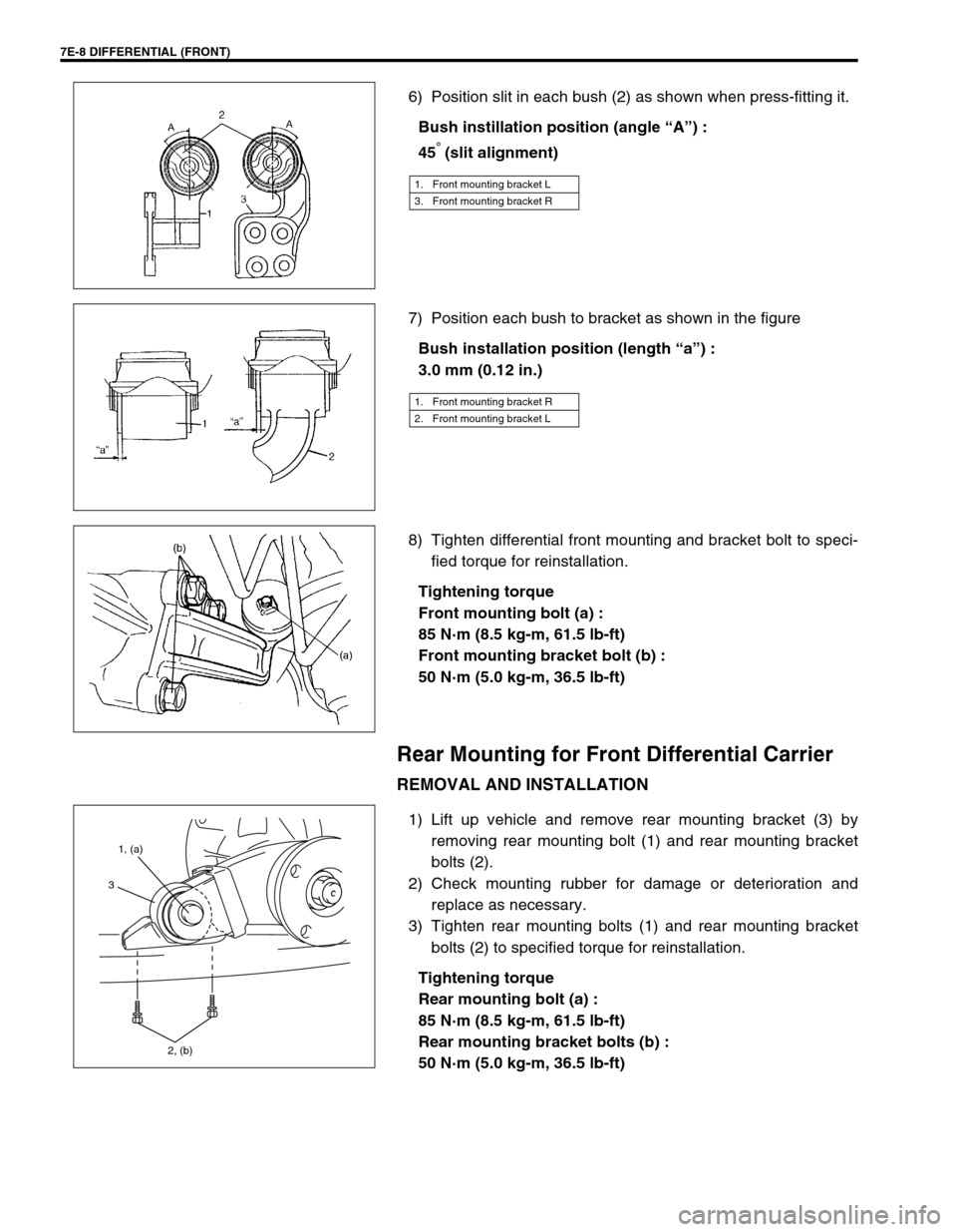
6) Position slit in each bush (2) as shown when press-fitting it.
Bush instillation position (angle “A”) :
45
° (slit alignment)
7) Position each bush to bracket as shown in the figure
Bush installation position (length “a”) :
3.0 mm (0.12 in.)
8) Tighten differential front mounting and bracket bolt to speci-
fied torque for reinstallation.
Tightening torque
Front mounting bolt (a) :
85 N·m (8.5 kg-m, 61.5 lb-ft)
Front mounting bracket bolt (b) :
50 N·m (5.0 kg-m, 36.5 lb-ft)
Rear Mounting for Front Differential Carrier
REMOVAL AND INSTALLATION
1) Lift up vehicle and remove rear mounting bracket (3) by
removing rear mounting bolt (1) and rear mounting bracket
bolts (2).
2) Check mounting rubber for damage or deterioration and
replace as necessary.
3) Tighten rear mounting bolts (1) and rear mounting bracket
bolts (2) to specified torque for reinstallation.
Tightening torque
Rear mounting bolt (a) :
85 N·m (8.5 kg-m, 61.5 lb-ft)
Rear mounting bracket bolts (b) :
50 N·m (5.0 kg-m, 36.5 lb-ft)
1. Front mounting bracket L
3. Front mounting bracket R
1. Front mounting bracket R
2. Front mounting bracket L
1, (a)
2, (b)
3
Page 546 of 656
BODY SERVICE 9-1
9
SECTION 9
BODY SERVICE
CONTENTS
Glass, Windows and Mirror .............................. 9-2
Quarter Window .............................................. 9-2
Body Structure .................................................. 9-3
Under Body Dimensions ................................. 9-3
Body Dimensions ............................................ 9-4
Seat..................................................................... 9-8
Second Seat .................................................... 9-8
Third Seat (If Equipped) .................................. 9-9
Paint and Coatings.......................................... 9-10Sealant Application Area............................... 9-10
Undercoating/Anti-corrosion Compound
Application Area ............................................ 9-17
Exterior and Interior Trim ............................... 9-19
Floor Carpet .................................................. 9-19
Front floor carpet ....................................... 9-19
Rear floor carpet (without third seat
vehicle) ...................................................... 9-20
Head Lining ................................................... 9-20
WARNING:
For vehicles equipped with Supplemental Restraint (Air Bag) System:
Service on and around the air bag system components or wiring must be performed only by an
authorized SUZUKI dealer. Refer to “Air Bag System Components and Wiring Location View” under
“General Description” in air bag system section in order to confirm whether you are performing ser-
vice on or near the air bag system components or wiring. Please observe all WARNINGS and “Ser-
vice Precautions” under “On-Vehicle Service” in air bag system section before performing service
on or around the air bag system components or wiring. Failure to follow WARNINGS could result in
unintentional activation of the system or could render the system inoperative. Either of these two
conditions may result in severe injury.
Technical service work must be started at least 90 seconds after the ignition switch is turned to the
“LOCK” position and the negative cable is disconnected from the battery. Otherwise, the system
may be activated by reserve energy in the Sensing and Diagnostic Module (SDM).
When body servicing, if shock may be applied to air bag system component parts, remove those
parts beforehand. (Refer to Section 10B.)
NOTE:
For the descriptions (items) not found in this section, refer to the same section of the Service Man-
ual mentioned in the FOREWORD of this manual.
Fasteners are important attaching parts in that they could affect the performance of vital compo-
nents and systems, and/or could result in major repair expense. They must be replaced with one of
the same part number of with an equivalent part if replacement becomes necessary.
Do not use a replacement part of lesser quality or substitute a design. Torque values must be used
as specified during reassembly to assure proper retention of these parts.