1999 SUZUKI GRAND VITARA section 6E2
[x] Cancel search: section 6E2Page 257 of 656

6-1-96 ENGINE GENERAL INFORMATION AND DIAGNOSIS (H27 ENGINE)
DTC P0430 Catalyst System Efficiency Below Threshold (Bank 2)
SYSTEM DIAGRAM
CIRCUIT DESCRIPTION
Exhaust oxygen concentration at the pre-catalyst and the post-catalyst of WU-TWC is detected from HO2S-1
and HO2S-2 respectively and accordingly ECM (PCM) controls the closed loop which then controls the fuel
injection volume. (Refer to Section 6E2.) While the above control is going on and if WU-TWC is in good condi-
tion, the output voltage of HO2S-2 is maintained at specified level. As WU-TWC becomes deteriorated, even
when the above control is going on, the exhaust gas which has passed TWC then passes HO2S-2 at the
exhaust oxygen concentration similar to that of the pre-catalyst without being oxygenated or converted. Thus,
waveforms of HO2S-1 and HO2S-2 output voltages become alike. ECM (PCM) judges deterioration of WU-TWC
by comparing waveforms of HO2S-1 and HO2S-2.
DTC DETECTING CONDITION AND TROUBLE AREA
1. HO2S-1 (Bank-2) 4. TWC
2. HO2S-2 (Bank-2) 5. ECM (PCM)
3. WU-TWC
DTC DETECTING CONDITION TROUBLE AREA
While running under conditions described for DTC CON-
FIRMATION PROCEDURE, output waveform of HO2S-1
becomes similar to that of HO2S-2.
(2 driving cycle detection logic)• Exhaust gas leakage
• Warm up three way catalytic converter
• Heated oxygen sensor – 2 or its circuit
•ECM (PCM)
Page 270 of 656
ENGINE GENERAL INFORMATION AND DIAGNOSIS (H27 ENGINE) 6-1-109
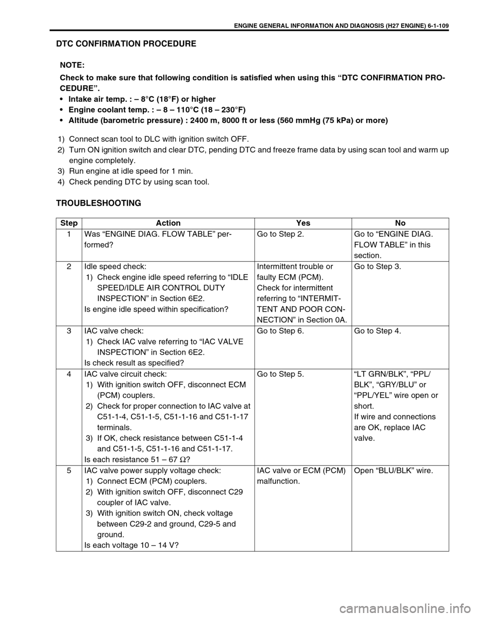
DTC CONFIRMATION PROCEDURE
1) Connect scan tool to DLC with ignition switch OFF.
2) Turn ON ignition switch and clear DTC, pending DTC and freeze frame data by using scan tool and warm up
engine completely.
3) Run engine at idle speed for 1 min.
4) Check pending DTC by using scan tool.
TROUBLESHOOTING
NOTE:
Check to make sure that following condition is satisfied when using this “DTC CONFIRMATION PRO-
CEDURE”.
Intake air temp. : – 8°C (18°F) or higher
Engine coolant temp. : – 8 – 110°C (18 – 230°F)
Altitude (barometric pressure) : 2400 m, 8000 ft or less (560 mmHg (75 kPa) or more)
Step Action Yes No
1Was “ENGINE DIAG. FLOW TABLE” per-
formed?Go to Step 2. Go to “ENGINE DIAG.
FLOW TABLE” in this
section.
2 Idle speed check:
1) Check engine idle speed referring to “IDLE
SPEED/IDLE AIR CONTROL DUTY
INSPECTION” in Section 6E2.
Is engine idle speed within specification?Intermittent trouble or
faulty ECM (PCM).
Check for intermittent
referring to “INTERMIT-
TENT AND POOR CON-
NECTION” in Section 0A.Go to Step 3.
3 IAC valve check:
1) Check IAC valve referring to “IAC VALVE
INSPECTION” in Section 6E2.
Is check result as specified?Go to Step 6. Go to Step 4.
4 IAC valve circuit check:
1) With ignition switch OFF, disconnect ECM
(PCM) couplers.
2) Check for proper connection to IAC valve at
C51-1-4, C51-1-5, C51-1-16 and C51-1-17
terminals.
3) If OK, check resistance between C51-1-4
and C51-1-5, C51-1-16 and C51-1-17.
Is each resistance 51 – 67 Ω?Go to Step 5.“LT GRN/BLK”, “PPL/
BLK”, “GRY/BLU” or
“PPL/YEL” wire open or
short.
If wire and connections
are OK, replace IAC
valve.
5 IAC valve power supply voltage check:
1) Connect ECM (PCM) couplers.
2) With ignition switch OFF, disconnect C29
coupler of IAC valve.
3) With ignition switch ON, check voltage
between C29-2 and ground, C29-5 and
ground.
Is each voltage 10 – 14 V?IAC valve or ECM (PCM)
malfunction.Open “BLU/BLK” wire.
Page 273 of 656

6-1-112 ENGINE GENERAL INFORMATION AND DIAGNOSIS (H27 ENGINE)
1) Connect scan tool to DLC with ignition switch OFF.
2) Turn ON ignition switch and clear DTC, pending DTC and freeze frame data by using scan tool and warm up
engine completely.
3) Run engine at idle speed for 1 min. (engine coolant temp. becomes 76°C (169°F) or more).
4) Increase vehicle speed to 80 km/h (50 mph).
5) Keep driving above vehicle speed for 1 min (Change of vehicle speed is permitted in this step).
6) Stop vehicle and check pending DTC by using scan tool.
TROUBLESHOOTING
Step Action Yes No
1Was “ENGINE DIAG. FLOW TABLE” per-
formed?Go to Step 2. Go to “ENGINE DIAG.
FLOW TABLE” in this
section.
2 MAP sensor signal check :
1) Remove ECM (PCM) cover.
2) Check voltage between C51-3-8 and C51-
3-25 under following conditions.
•With ignition switch ON leaving engine OFF
: 0.2 V or higher
•At idling : 4.6 V or lower
Is check result as specified?Intermittent trouble or
faulty ECM (PCM).
Check for intermittent
referring to “INTERMIT-
TENT AND POOR CON-
NECTION” in Section 0A.Go to Step 3.
3 MAP sensor check :
1) Disconnect connector from MAP sensor.
2) Check for proper connection to MAP sensor
at each terminal.
3) If OK, check MAP sensor for performance
referring to “MAP SENSOR INSPECTION”
in Section 6E2.
Is check result satisfactory?“RED/WHT”, “GRY/YEL”
or “GRY/RED” circuit
open/short.
If wire and connections
are OK, substitute a
known-good ECM (PCM)
and recheck.Replace MAP sensor.
Page 278 of 656
ENGINE GENERAL INFORMATION AND DIAGNOSIS (H27 ENGINE) 6-1-117
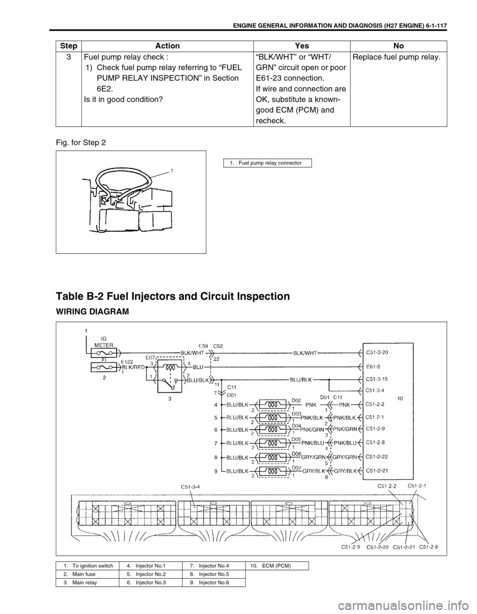
Fig. for Step 2
Table B-2 Fuel Injectors and Circuit Inspection
WIRING DIAGRAM
3 Fuel pump relay check :
1) Check fuel pump relay referring to “FUEL
PUMP RELAY INSPECTION” in Section
6E2.
Is it in good condition?“BLK/WHT” or “WHT/
GRN” circuit open or poor
E61-23 connection.
If wire and connection are
OK, substitute a known-
good ECM (PCM) and
recheck.Replace fuel pump relay. Step Action Yes No
1. Fuel pump relay connector
1. To ignition switch 4. Injector No.1 7. Injector No.4 10. ECM (PCM)
2. Main fuse 5. Injector No.2 8. Injector No.5
3. Main relay 6. Injector No.3 9. Injector No.6
Page 279 of 656
6-1-118 ENGINE GENERAL INFORMATION AND DIAGNOSIS (H27 ENGINE)
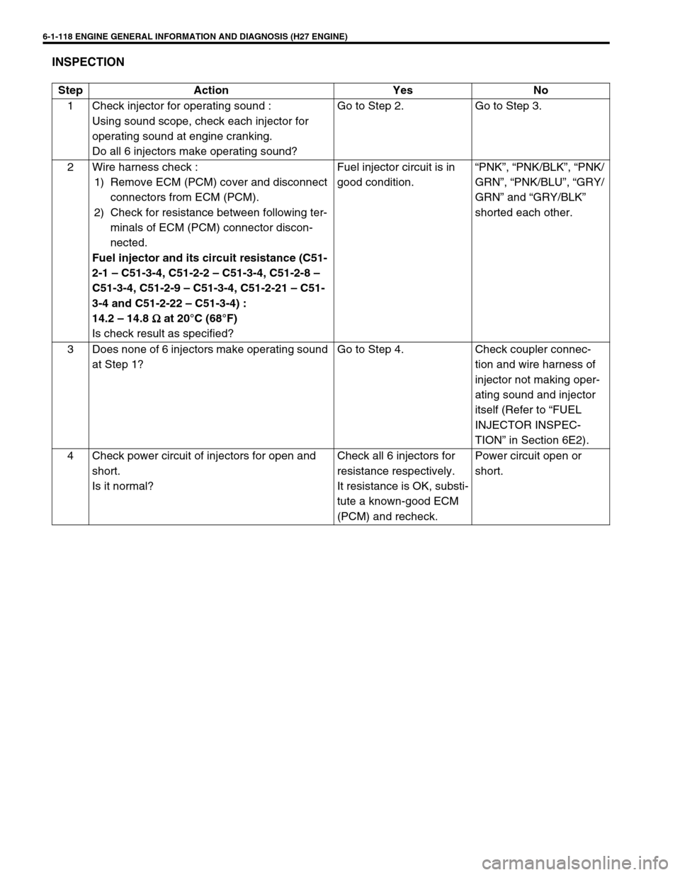
INSPECTION
Step Action Yes No
1 Check injector for operating sound :
Using sound scope, check each injector for
operating sound at engine cranking.
Do all 6 injectors make operating sound?Go to Step 2. Go to Step 3.
2 Wire harness check :
1) Remove ECM (PCM) cover and disconnect
connectors from ECM (PCM).
2) Check for resistance between following ter-
minals of ECM (PCM) connector discon-
nected.
Fuel injector and its circuit resistance (C51-
2-1 – C51-3-4, C51-2-2 – C51-3-4, C51-2-8 –
C51-3-4, C51-2-9 – C51-3-4, C51-2-21 – C51-
3-4 and C51-2-22 – C51-3-4) :
14.2 – 14.8
Ω
ΩΩ Ω at 20°C (68°F)
Is check result as specified?Fuel injector circuit is in
good condition.“PNK”, “PNK/BLK”, “PNK/
GRN”, “PNK/BLU”, “GRY/
GRN” and “GRY/BLK”
shorted each other.
3 Does none of 6 injectors make operating sound
at Step 1?Go to Step 4. Check coupler connec-
tion and wire harness of
injector not making oper-
ating sound and injector
itself (Refer to “FUEL
INJECTOR INSPEC-
TION” in Section 6E2).
4 Check power circuit of injectors for open and
short.
Is it normal?Check all 6 injectors for
resistance respectively.
It resistance is OK, substi-
tute a known-good ECM
(PCM) and recheck.Power circuit open or
short.
Page 282 of 656
ENGINE GENERAL INFORMATION AND DIAGNOSIS (H27 ENGINE) 6-1-121
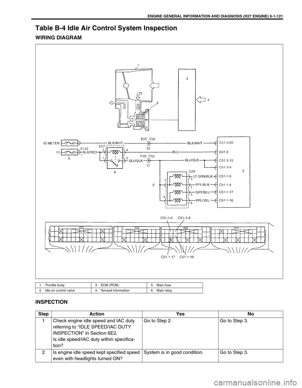
Table B-4 Idle Air Control System Inspection
WIRING DIAGRAM
INSPECTION
1. Throttle body 3. ECM (PCM) 5. Main fuse
2. Idle air control valve 4. Sensed information 6. Main relay
Step Action Yes No
1 Check engine idle speed and IAC duty
referring to “IDLE SPEED/IAC DUTY
INSPECTION” in Section 6E2.
Is idle speed/IAC duty within specifica-
tion?Go to Step 2. Go to Step 3.
2 Is engine idle speed kept specified speed
even with headlights turned ON?System is in good condition. Go to Step 3.
Page 283 of 656

6-1-122 ENGINE GENERAL INFORMATION AND DIAGNOSIS (H27 ENGINE)
3 Check IAC valve referring to “IAC VALVE
INSPECTION” in Section 6E2.
Is check result as specified?Go to Step 4. IAC valve malfunction, “BLU/
BLK”, “LT GRN/BLK”, “PPL/
BLK”, “GRY/BLU” or “PPL/
YEL” wire open or short or
poor coupler connection.
If all above are OK, substi-
tute a known-good ECM
(PCM) and recheck.
4 Was idle speed within specification in
Step 1?Check for following :
FIA valve, Vacuum leaks, air inhal-
ing, EVAP canister purge control
system, accessory engine load,
stuck of PCV valve, clog of idle air
passage, MAF sensor, TP sensor,
ECT sensor, EGR valve malfunc-
tion (leakage from valve seat), A/C
signal, transmission range switch
signal and power steering switch
signal.Go to Step 5.
5 Was idle speed higher than specification
in Step 1?Go to Step 6. Go to Step 8.
6 Check A/C (input) signal circuit referring
to Step 1 of “Table B-5”. (A/C signal can
be also checked by using SUZUKI scan
tool.)
Is it in good condition?Go to Step 7. A/C signal circuit open or
short, or A/C system mal-
function.
7 Was IAC duty less than about 2% in Step
1 of this table?
Check FIA valve.
Check abnormal air inhaling from
intake manifold, throttle body, PCV
valve and EVAP canister purge
control system.Check TP sensor (closed
throttle position) and ECT
sensor for performance.
If sensors are OK, substitute
a known-good ECM (PCM)
and recheck.
8 Check transmission range switch signal
referring to “INSPECTION OF ECM
(PCM) AND ITS CIRCUIT” in this section.
Is check result satisfactory?Go to Step 9. Transmission range switch
malfunction or its circuits
open or short.
9 Was IAC duty more than about 30% in
Step 1 of this table?Check parts or system which can
cause engine low idle.
Check FIA valve.
Air inhaling from between throttle
body and MAF sensor, EGR valve
malfunction (leakage from valve
seat), accessory engine load, clog
of idle air passage and etc.Substitute a known-good
ECM (PCM) and recheck. Step Action Yes No
Page 307 of 656
6A2-20 ENGINE MECHANICAL (H27 ENGINE)
12) Install oil pan and oil pump strainer.
Refer to “OIL PAN AND OIL PUMP STRAINER” in this sec-
tion.
13) Install cylinder head cover.
Refer to “CYLINDER HEAD COVER” in this section.
14) Install exhaust manifold.
Refer to “EXHAUST MANIFOLD” in this section.
15) Install radiator outlet pipe, radiator, cooling fan and water
hose.
Refer to “COOLING WATER PIPES OR HOSES”, “RADIA-
TOR” and “COOLING FAN AND FAN CLUTCH” in Section
6B.
16) Install throttle body and intake manifold.
Refer to “THROTTLE BODY AND INTAKE MANIFOLD” in
this section.
17) Adjust water pump drive belt tension.
Refer to “COOLING FAN BELT TENSION CHECK AND
ADJUSTMENT” in Section 6B.
18) Adjust power steering pump drive belt tension.
Refer to “POWER STEERING PUMP DRIVE BELT” in Sec-
tion 3B1.
19) Adjust accelerator cable play and A/T throttle cable play.
Refer to “ACCELERATOR CABLE ADJUSTMENT” and “A/T
THROTTLE CABLE ADJUSTMENT (A/T VEHICLE)” in Sec-
tion 6E2.
20) Check to ensure that all removed parts are back in place.
Reinstall any necessary parts which have not been rein-
stalled.
21) Refill engine with engine oil, referring to “ENGINE OIL
CHANGE” in Section 0B.
22) Refill cooling system referring to “COOLING SYSTEM
FLUSH AND REFILL” in Section 6B.
23) Refill front differential housing with gear oil if drained, refer-
ring to “MAINTENANCE SERVICE” in Section 7E.
24) Connect negative cable at battery.
25) Check ignition timing and adjust as necessary, referring to
“IGNITION TIMING CHECK AND ADJUSTMENT” in Section
6F2.
26) Verify that there is no fuel leakage, water leakage, oil leak-
age and exhaust gas leakage at each connection.
27) Check wheel alignment, referring to “STEERING ANGLE” in
Section 3A.