Page 318 of 656
ENGINE MECHANICAL (H27 ENGINE) 6A2-31
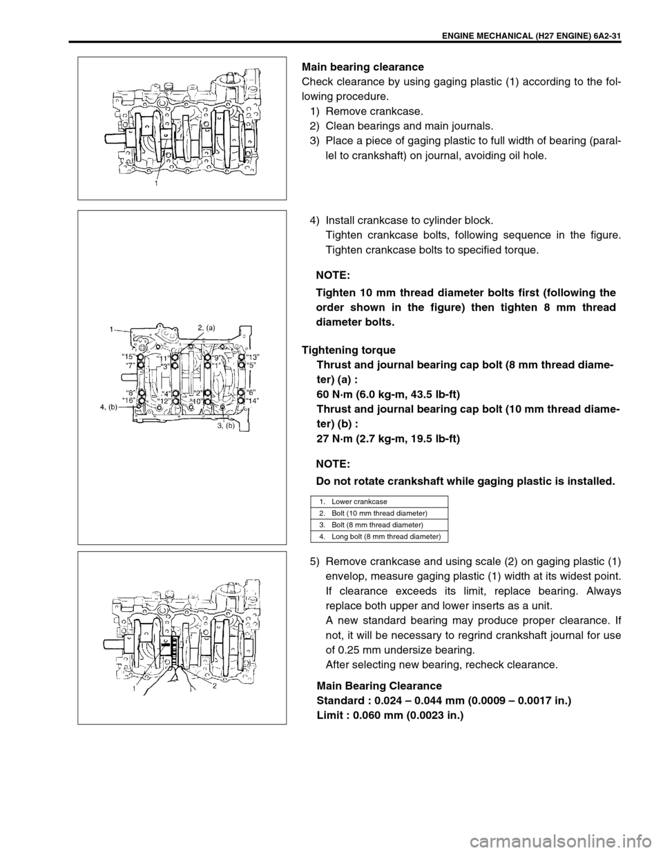
Main bearing clearance
Check clearance by using gaging plastic (1) according to the fol-
lowing procedure.
1) Remove crankcase.
2) Clean bearings and main journals.
3) Place a piece of gaging plastic to full width of bearing (paral-
lel to crankshaft) on journal, avoiding oil hole.
4) Install crankcase to cylinder block.
Tighten crankcase bolts, following sequence in the figure.
Tighten crankcase bolts to specified torque.
Tightening torque
Thrust and journal bearing cap bolt (8 mm thread diame-
ter) (a) :
60 N·m (6.0 kg-m, 43.5 lb-ft)
Thrust and journal bearing cap bolt (10 mm thread diame-
ter) (b) :
27 N·m (2.7 kg-m, 19.5 lb-ft)
5) Remove crankcase and using scale (2) on gaging plastic (1)
envelop, measure gaging plastic (1) width at its widest point.
If clearance exceeds its limit, replace bearing. Always
replace both upper and lower inserts as a unit.
A new standard bearing may produce proper clearance. If
not, it will be necessary to regrind crankshaft journal for use
of 0.25 mm undersize bearing.
After selecting new bearing, recheck clearance.
Main Bearing Clearance
Standard : 0.024 – 0.044 mm (0.0009 – 0.0017 in.)
Limit : 0.060 mm (0.0023 in.)
NOTE:
Tighten 10 mm thread diameter bolts first (following the
order shown in the figure) then tighten 8 mm thread
diameter bolts.
NOTE:
Do not rotate crankshaft while gaging plastic is installed.
1. Lower crankcase
2. Bolt (10 mm thread diameter)
3. Bolt (8 mm thread diameter)
4. Long bolt (8 mm thread diameter)
Page 320 of 656
ENGINE MECHANICAL (H27 ENGINE) 6A2-33
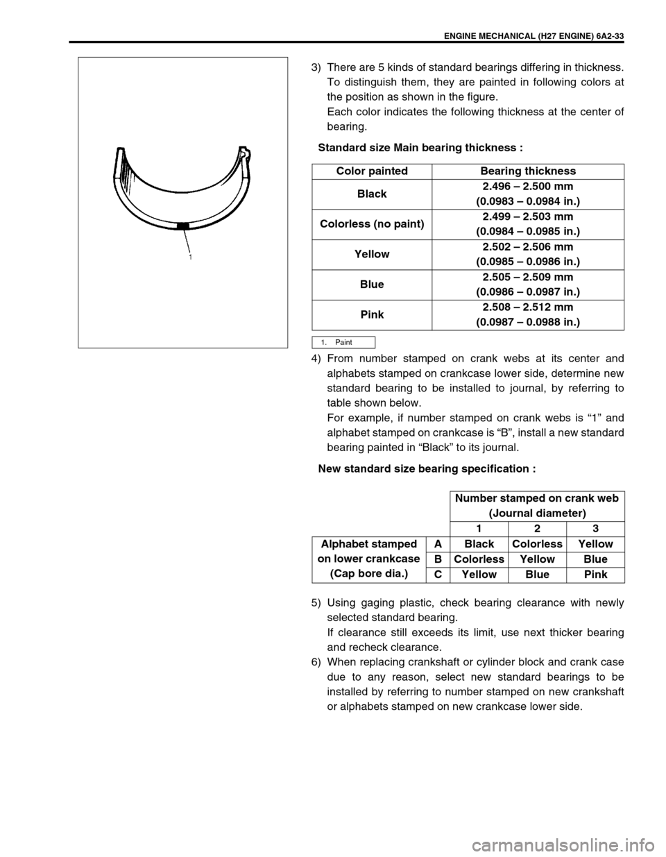
3) There are 5 kinds of standard bearings differing in thickness.
To distinguish them, they are painted in following colors at
the position as shown in the figure.
Each color indicates the following thickness at the center of
bearing.
Standard size Main bearing thickness :
4) From number stamped on crank webs at its center and
alphabets stamped on crankcase lower side, determine new
standard bearing to be installed to journal, by referring to
table shown below.
For example, if number stamped on crank webs is “1” and
alphabet stamped on crankcase is “B”, install a new standard
bearing painted in “Black” to its journal.
New standard size bearing specification :
5) Using gaging plastic, check bearing clearance with newly
selected standard bearing.
If clearance still exceeds its limit, use next thicker bearing
and recheck clearance.
6) When replacing crankshaft or cylinder block and crank case
due to any reason, select new standard bearings to be
installed by referring to number stamped on new crankshaft
or alphabets stamped on new crankcase lower side.Color painted Bearing thickness
Black2.496 – 2.500 mm
(0.0983 – 0.0984 in.)
Colorless (no paint)2.499 – 2.503 mm
(0.0984 – 0.0985 in.)
Yellow2.502 – 2.506 mm
(0.0985 – 0.0986 in.)
Blue2.505 – 2.509 mm
(0.0986 – 0.0987 in.)
Pink2.508 – 2.512 mm
(0.0987 – 0.0988 in.)
1. Paint
Number stamped on crank web
(Journal diameter)
123
Alphabet stamped
on lower crankcase
(Cap bore dia.)A Black Colorless Yellow
B Colorless Yellow Blue
C Yellow Blue Pink
Page 348 of 656
ENGINE AND EMISSION CONTROL SYSTEM (SEQUENTIAL MULTIPORT FUEL INJECTION FOR H27 ENGINE) 6E2-15
Idle Speed/Idle Air Control (IAC) Duty Inspec-
tion
Before idle speed/IAC duty check, make sure of the following.
•Lead wires and hoses of engine/emission control systems
are connected securely.
•Accelerator cable is adjusted.
•Ignition timing is within specification.
•All accessories (wipers, heater, lights, A/C, etc.) are out of
service.
•Air cleaner has been properly installed and is in good condi-
tion.
•ECM (PCM) does not detect any malfunction DTC.
After above items are all confirmed, check idle speed and IAC
duty as follows.
[Using SUZUKI scan tool]
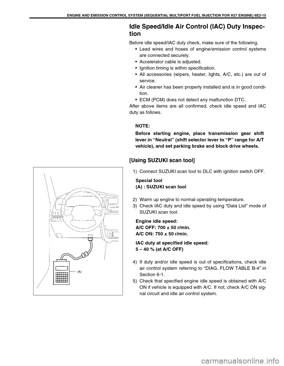
1) Connect SUZUKI scan tool to DLC with ignition switch OFF.
Special tool
(A) : SUZUKI scan tool
2) Warm up engine to normal operating temperature.
3) Check IAC duty and idle speed by using “Data List” mode of
SUZUKI scan tool.
Engine idle speed:
A/C OFF: 700 ± 50 r/min.
A/C ON: 750 ± 50 r/min.
IAC duty at specified idle speed:
5 – 40 % (at A/C OFF)
4) If duty and/or idle speed is out of specifications, check idle
air control system referring to “DIAG. FLOW TABLE B-4” in
Section 6-1.
5) Check that specified engine idle speed is obtained with A/C
ON if vehicle is equipped with A/C. If not, check A/C ON sig-
nal circuit and idle air control system. NOTE:
Before starting engine, place transmission gear shift
lever in “Neutral” (shift selector lever to “P” range for A/T
vehicle), and set parking brake and block drive wheels.
Page 447 of 656
7B1-38 AUTOMATIC TRANSMISSION (4 A/T)
Stall Test
This test is to check overall performance of automatic transmission and engine by measuring stall speed at “D”
and “R” ranges. Be sure to perform this test only when transmission fluid is at normal operating temperature and
its level is between FULL and LOW marks.
1) Apply parking brake and block wheels.
2) Install tachometer.
3) Start engine with select lever shifted to “P”.
4) Depress brake pedal fully.
5) Shift select lever to “D” and depress accelerator pedal fully while watching tachometer. Read engine rpm
quickly when it has become constant (stall speed).
6) Release accelerator pedal immediately after stall speed is checked.
7) In the same way, check stall speed in “R” range.
8) Stall speed should be within the following specification.
Stall speed :
2,460 – 2,760 r/min.
TROUBLESHOOTING
CAUTION:
Do not run engine at stall more than 5 seconds continuously, for fluid temperature may rise exces-
sively high.
After performing stall test, be sure to leave engine running at idle for longer than 30 seconds before
another stall test.
Condition Possible cause
Lower than standard level•Faulty engine output
•Defective torque converter
Higher than standard level in “D” range•Slippery O/D clutch
•Slippery forward clutch
•Malfunctioning O/D one-way clutch
•Malfunctioning one-way clutch No. 2
•Low line pressure
Higher than standard level in “R” range•Slippery direct clutch
•Slippery reverse brake
•Low fluid pressure
•Slippery O/D clutch
•Defective O/D one-way clutch
Page 598 of 656
AIR BAG SYSTEM 10B-21
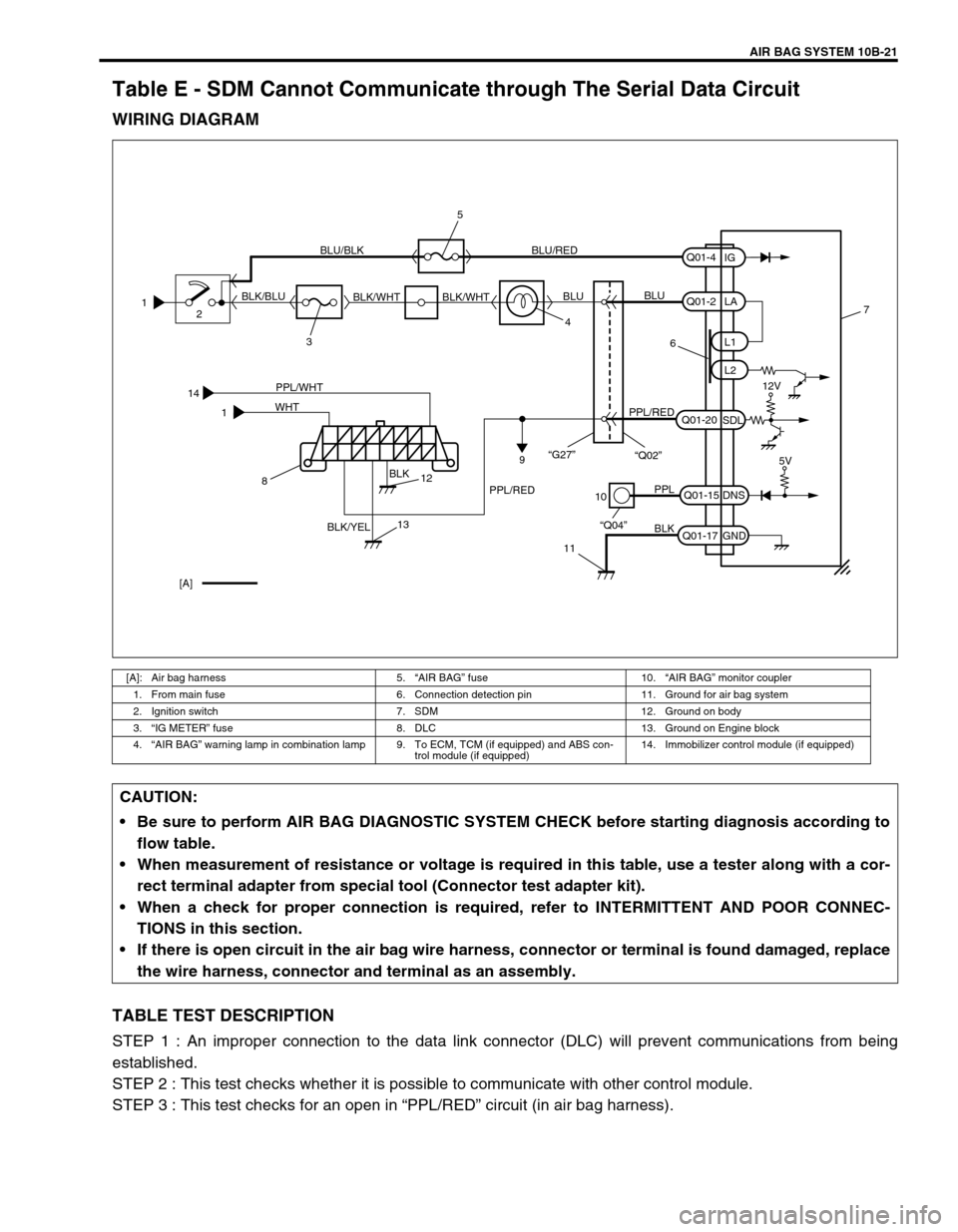
Table E - SDM Cannot Communicate through The Serial Data Circuit
WIRING DIAGRAM
TABLE TEST DESCRIPTION
STEP 1 : An improper connection to the data link connector (DLC) will prevent communications from being
established.
STEP 2 : This test checks whether it is possible to communicate with other control module.
STEP 3 : This test checks for an open in “PPL/RED” circuit (in air bag harness).
[A]: Air bag harness 5.“AIR BAG” fuse 10.“AIR BAG” monitor coupler
1. From main fuse 6. Connection detection pin 11. Ground for air bag system
2. Ignition switch 7. SDM 12. Ground on body
3.“IG METER” fuse 8. DLC 13. Ground on Engine block
4.“AIR BAG” warning lamp in combination lamp 9. To ECM, TCM (if equipped) and ABS con-
trol module (if equipped)14. Immobilizer control module (if equipped)
14
1PPL/WHT
BLK
BLK/YEL WHT
10
11
PPL
BLK
“Q04”Q01-15
Q01-17DNS
GND7
[A]5V
812
13
1
2
34 BLK/BLUBLU/BLK BLU/RED
BLK/WHT BLK/WHTBLUBLU
6
PPL/REDPPL/RED
9
Q01-2
Q01-20L1
L2
SDLLA
Q01-4
IG
12V
“G27”
“Q02”
5
CAUTION:
Be sure to perform AIR BAG DIAGNOSTIC SYSTEM CHECK before starting diagnosis according to
flow table.
When measurement of resistance or voltage is required in this table, use a tester along with a cor-
rect terminal adapter from special tool (Connector test adapter kit).
When a check for proper connection is required, refer to INTERMITTENT AND POOR CONNEC-
TIONS in this section.
If there is open circuit in the air bag wire harness, connector or terminal is found damaged, replace
the wire harness, connector and terminal as an assembly.
Page:
< prev 1-8 9-16 17-24