Page 305 of 656

6A2-18 ENGINE MECHANICAL (H27 ENGINE)
INSPECTION
Valve guides
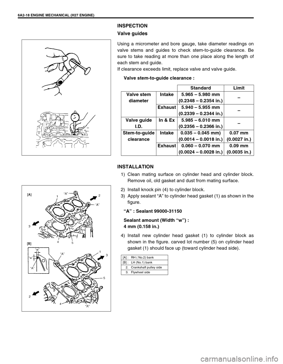
Using a micrometer and bore gauge, take diameter readings on
valve stems and guides to check stem-to-guide clearance. Be
sure to take reading at more than one place along the length of
each stem and guide.
If clearance exceeds limit, replace valve and valve guide.
Valve stem-to-guide clearance :
INSTALLATION
1) Clean mating surface on cylinder head and cylinder block.
Remove oil, old gasket and dust from mating surface.
2) Install knock pin (4) to cylinder block.
3) Apply sealant “A” to cylinder head gasket (1) as shown in the
figure.
“A” : Sealant 99000-31150
Sealant amount (Width “w”) :
4 mm (0.158 in.)
4) Install new cylinder head gasket (1) to cylinder block as
shown in the figure. carved lot number (5) on cylinder head
gasket (1) should face up (toward cylinder head side).Standard Limit
Valve stem
diameterIntake 5.965 – 5.980 mm
(0.2348 – 0.2354 in.)–
Exhaust 5.940 – 5.955 mm
(0.2339 – 0.2344 in.)–
Valve guide
I.D.In & Ex 5.985 – 6.010 mm
(0.2356 – 0.2366 in.)–
Stem-to-guide
clearanceIntake 0.035 – 0.045 mm)
(0.0014 – 0.0018 in.)0.07 mm
(0.0027 in.)
Exhaust 0.060 – 0.070 mm
(0.0024 – 0.0028 in.)0.09 mm
(0.0035 in.)
[A] : RH ( No.2) bank
[B] : LH (No.1) bank
2. Crankshaft pulley side
3. Flywheel side
Page 306 of 656

ENGINE MECHANICAL (H27 ENGINE) 6A2-19
5) Install cylinder head to block.
After applying oil to cylinder head bolts, tighten them gradu-
ally as follows.
a) Tighten all bolts to 53 N·m (5.3 kg-m, 38.5 lb-ft) according
to numerical order in the figure.
b) In the same manner as in a), tighten them to 84 N·m (8.4
kg-m, 61.0 lb-ft).
c) Loosen all bolts until tightening torque is reduced to 0 in
reverse order of tightening.
d) In the same manner as in a), tighten them to 53 N·m (5.3
kg-m, 38.5 lb-ft).
e) In the same manner as in a) again, tighten them to speci-
fied torque.
Tightening torque
Cylinder head bolt (a) : 105 N·m (10.5 kg-m, 76.0 lb-ft)
Cylinder head bolt (hex hole bolt) (b) :
11 N·m (1.1 kg-m, 7.5 lb-ft)
6) Install water outlet cap.
7) Check timing mark on crankshaft as shown in the figure.
8) Install valve lash adjuster, camshaft, CMP sensor and RH
bank 2nd timing chain.
Refer to “CAMSHAFT AND VALVE LASH ADJUSTER” and
“RH (NO.2) BANK 2ND TIMING CHAIN AND CHAIN TEN-
SIONER” in this section. For CMP sensor, refer to “CMP
SENSOR” in Section 6F2.
9) Install 1st timing chain.
Refer to “1ST TIMING CHAIN AND CHAIN TENSIONER” in
this section.
10) Install LH bank 2nd timing chain.
Refer to “LH (NO.1) BANK 2ND TIMING CHAIN AND CHAIN
TENSIONER” in this section.
11) Install timing chain cover.
Refer to “TIMING CHAIN COVER” in this section. NOTE:
Don’t forget to install (b) bolts as shown in the figure.
1. Hex hole bolt
2. Crankshaft pulley side
3. Flywheel side
[A] RH bank
[B] LH bank
1. Crank timing pulley key
2. Oil jet
Page 308 of 656
ENGINE MECHANICAL (H27 ENGINE) 6A2-21
Piston, Piston Rings, Connecting Rods and Cylinders
1. Top ring 5. Connecting rod :
Clean bearing installing surface when install.9. Piston pin circlip Tightening Torque
2. 2nd ring 6. Connecting rod bearing cap :
Clean bearing installing surface when install.10. Cylinder block Do not reuse
3. Oil ring 7. Connecting rod bearing :
Clean outer surface when install.11. Bearing cap nut Apply engine oil to sliding
surface of each parts.
4. Piston 8. Piston pin
Page 311 of 656

6A2-24 ENGINE MECHANICAL (H27 ENGINE)
ASSEMBLY
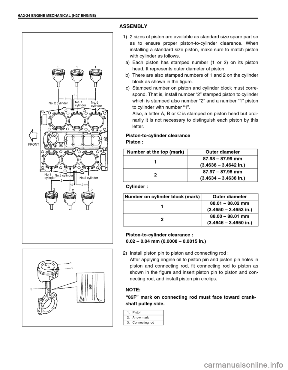
1) 2 sizes of piston are available as standard size spare part so
as to ensure proper piston-to-cylinder clearance. When
installing a standard size piston, make sure to match piston
with cylinder as follows.
a) Each piston has stamped number (1 or 2) on its piston
head. It represents outer diameter of piston.
b) There are also stamped numbers of 1 and 2 on the cylinder
block as shown in the figure.
c) Stamped number on piston and cylinder block must corre-
spond. That is, install number “2” stamped piston to cylinder
which is stamped also number “2” and a number “1” piston
to cylinder with number “1”.
Also, a letter A, B or C is stamped on piston head but ordi-
narily it is not necessary to distinguish each piston by this
letter.
Piston-to-cylinder clearance
Piston :
Cylinder :
Piston-to-cylinder clearance :
0.02 – 0.04 mm (0.0008 – 0.0015 in.)
2) Install piston pin to piston and connecting rod :
After applying engine oil to piston pin and piston pin holes in
piston and connecting rod, fit connecting rod to piston as
shown in the figure and insert piston pin to piston and con-
necting rod, and install piston pin circlips. Number at the top (mark) Outer diameter
187.98 – 87.99 mm
(3.4638 – 3.4642 in.)
287.97 – 87.98 mm
(3.4634 – 3.4638 in.)
Number on cylinder block (mark) Outer diameter
188.01 – 88.02 mm
(3.4650 – 3.4653 in.)
288.00 – 88.01 mm
(3.4646 – 3.4650 in.)
NOTE:
“86F” mark on connecting rod must face toward crank-
shaft pulley side.
1. Piston
2. Arrow mark
3. Connecting rod
Page 314 of 656

ENGINE MECHANICAL (H27 ENGINE) 6A2-27
12) Disconnect the following electric lead wires :
•Injector wire coupler
•CMP sensor coupler
•Ignition coil couplers
•CKP sensor coupler
•MAP sensor coupler
•TP sensor (1) coupler
•IAC valve (2) coupler
•Earth wire (3) from surge tank
•EVAP canister purge valve coupler
•EGR valve coupler
•Oxygen sensor -1 and -2 couplers referring to “Exhaust Man-
ifold” in this section
•Coolant temperature sensor coupler
•Knock sensor coupler
•Generator wires
•Starter wires
•Oil pressure wire
•P/S pump wire
•Earth wire from generator bracket
•Engine block heater (if equipped)
13) Remove clamps and brackets.
14) Disconnect the following hoses :
•Heater hose from heater water pipe
•Heater hose from water outlet cap
•EVAP canister hose from canister pipe
•Brake booster vacuum hose
15) Remove EVAP canister purge valve (5).
16) Disconnect the following hoses at the location shown in the
figure :
•Fuel feed hose (1) from fuel feed pipe
•Fuel return hose from (2) fuel return pipe
17) Remove P/S pump assembly. Refer to “POWER STEERING
PUMP” in Section 3B1.
18) Remove A/C compressor assembly. Refer to “COMPRES-
SOR ASSEMBLY” in Section 1B.
19) Remove steering shaft lower assembly. Refer to “STEERING
LOWER SHAFT ASSEMBLY” in Section 3C1.
20) Raise vehicle.
21) Remove front differential housing with differential from chas-
sis if equipped. Refer to “DISMOUNTING” in Section 7E.
22) Remove exhaust No.1 pipe. Refer to “EXHAUST MANI-
FOLD” in this section.
23) Remove exhaust manifold stiffener from transmission.
4. Clamp bracket
6. EGR valve
7. Heater hose
2
14
3
75
6
Page 315 of 656

6A2-28 ENGINE MECHANICAL (H27 ENGINE)
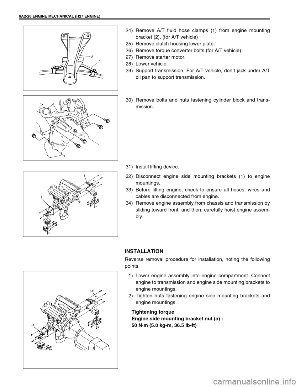
24) Remove A/T fluid hose clamps (1) from engine mounting
bracket (2). (for A/T vehicle)
25) Remove clutch housing lower plate.
26) Remove torque converter bolts (for A/T vehicle).
27) Remove starter motor.
28) Lower vehicle.
29) Support transmission. For A/T vehicle, don’t jack under A/T
oil pan to support transmission.
30) Remove bolts and nuts fastening cylinder block and trans-
mission.
31) Install lifting device.
32) Disconnect engine side mounting brackets (1) to engine
mountings.
33) Before lifting engine, check to ensure all hoses, wires and
cables are disconnected from engine.
34) Remove engine assembly from chassis and transmission by
sliding toward front, and then, carefully hoist engine assem-
bly.
INSTALLATION
Reverse removal procedure for installation, noting the following
points.
1) Lower engine assembly into engine compartment. Connect
engine to transmission and engine side mounting brackets to
engine mountings.
2) Tighten nuts fastening engine side mounting brackets and
engine mountings.
Tightening torque
Engine side mounting bracket nut (a) :
50 N·m (5.0 kg-m, 36.5 lb-ft)
Page 316 of 656

ENGINE MECHANICAL (H27 ENGINE) 6A2-29
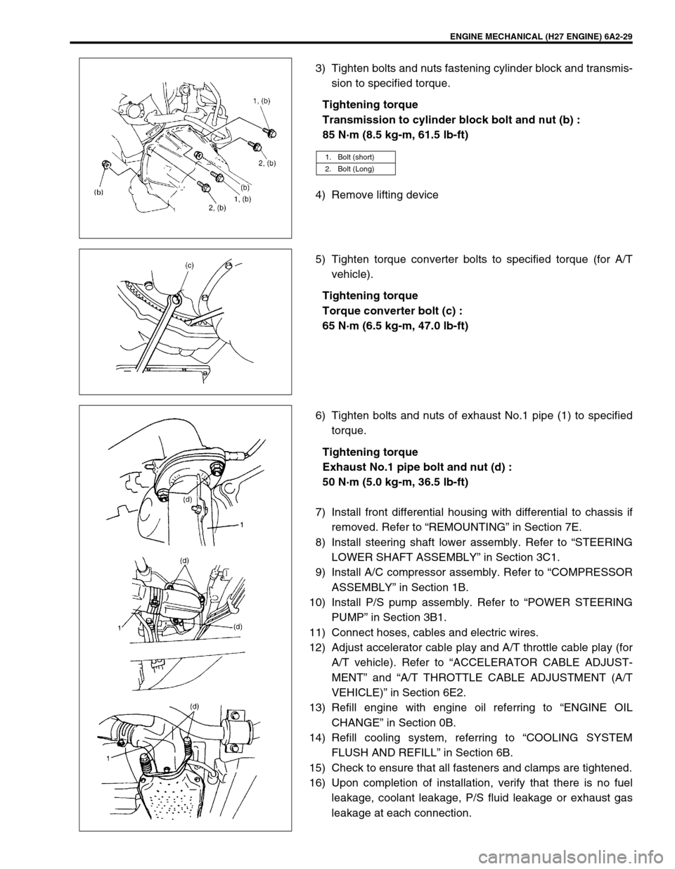
3) Tighten bolts and nuts fastening cylinder block and transmis-
sion to specified torque.
Tightening torque
Transmission to cylinder block bolt and nut (b) :
85 N·m (8.5 kg-m, 61.5 lb-ft)
4) Remove lifting device
5) Tighten torque converter bolts to specified torque (for A/T
vehicle).
Tightening torque
Torque converter bolt (c) :
65 N·m (6.5 kg-m, 47.0 lb-ft)
6) Tighten bolts and nuts of exhaust No.1 pipe (1) to specified
torque.
Tightening torque
Exhaust No.1 pipe bolt and nut (d) :
50 N·m (5.0 kg-m, 36.5 lb-ft)
7) Install front differential housing with differential to chassis if
removed. Refer to “REMOUNTING” in Section 7E.
8) Install steering shaft lower assembly. Refer to “STEERING
LOWER SHAFT ASSEMBLY” in Section 3C1.
9) Install A/C compressor assembly. Refer to “COMPRESSOR
ASSEMBLY” in Section 1B.
10) Install P/S pump assembly. Refer to “POWER STEERING
PUMP” in Section 3B1.
11) Connect hoses, cables and electric wires.
12) Adjust accelerator cable play and A/T throttle cable play (for
A/T vehicle). Refer to “ACCELERATOR CABLE ADJUST-
MENT” and “A/T THROTTLE CABLE ADJUSTMENT (A/T
VEHICLE)” in Section 6E2.
13) Refill engine with engine oil referring to “ENGINE OIL
CHANGE” in Section 0B.
14) Refill cooling system, referring to “COOLING SYSTEM
FLUSH AND REFILL” in Section 6B.
15) Check to ensure that all fasteners and clamps are tightened.
16) Upon completion of installation, verify that there is no fuel
leakage, coolant leakage, P/S fluid leakage or exhaust gas
leakage at each connection.
1. Bolt (short)
2. Bolt (Long)
Page 317 of 656
6A2-30 ENGINE MECHANICAL (H27 ENGINE)
Main Bearings, Crankshaft and Cylinder Block
1. Cylinder block 6. Rear oil seal 11. O-ring [A]: Sealant application amount
2. Lower crankcase :
Apply sealant 99000-31150 to lower
crankcase mating surface.7. Flywheel (M/T) Drive plate
(A/T)12. Clutch housing plate Tightening Torque
3. Crankshaft 8. Water pump 13. Cap bolt Do not reuse
4. Main bearing 9. O-ring 14. Lower crankcase bolt Apply engine oil to sliding
surface of each parts.
5. Thrust bearing :
Set bearing facing grooved side to
crank weds.10. Timing chain oil jet 15. Knock sensor“a”: Width 3 mm (0.12 in.)
“b”: Height 2 mm (0.08 in.)