1999 SUBARU LEGACY low oil pressure
[x] Cancel search: low oil pressurePage 856 of 1456

(3) Remove the following parts from front cas-
ing.
CAUTION:
Discard old seal washer; replace with a new
one.
B4M1138A
(1) Seal washer
(2) Knock pin.....2 ea.
(3) Cam ring
(4) Rotor
(5) Vane.....10 ea.
(6) Side plate
(7) O-ring.....2 ea.
2) Control valve
Slightly loosen outlet connector, and remove con-
nector. Remove the following parts for pump cas-
ing.
ISpool valve assembly
IFlow control spring
IConnector
IO-ring
G4M0180
3) Shaft
(1) Remove snap ring from front casing.
G4M0181
(2) Remove shaft using a hand press.
CAUTION:
IDiscard old drive shaft assembly; replace
with a new one.
IBe careful not to scratch or dent casing's
surface which serves as a seal.
G4M0182
(3) Pry oil seal off using a screwdriver.
CAUTION:
Be careful not to scratch inner surface of cas-
ing.
G4M0183
4) Remove pressure switch.
D: INSPECTION
Perform the following inspection procedures and
repair or replace defective parts.
63
[W8D0]4-3SERVICE PROCEDURE
8. Oil Pump (Power Steering System)
Page 859 of 1456
improper installation. Eliminate the cause of
trouble.
(2) Check followings by referring to ªCHECKº
article.
IExcessive play in pulley shaft
IDitch deflection of pulley
IResistance to rotation of pulley
IMeasurement of generated oil pressure
F: INSTALLATION
1) Install bracket on engine.
Tightening torque:
22
±2 N´m (2.2±0.2 kg-m, 15.9±1.4 ft-lb)
2) Install oil pump on oil tank as follows outside
the vehicle:
NOTE:
Prior to installation, make sure that all oil is
removed from oil pump, oil tank and pipe.
3) Place oil pump in vise.
CAUTION:
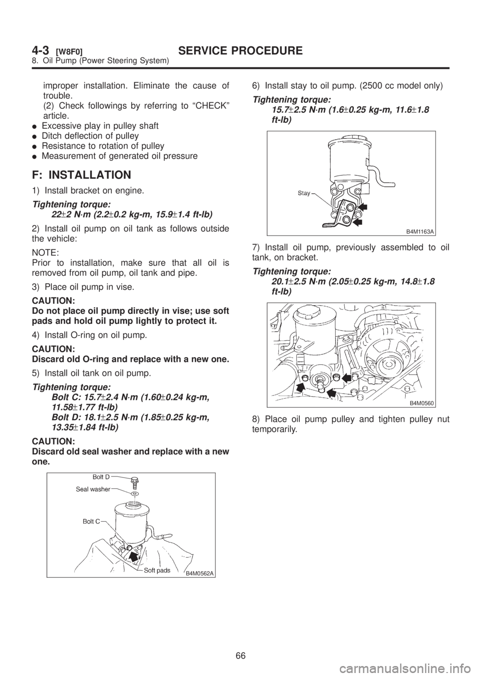
Do not place oil pump directly in vise; use soft
pads and hold oil pump lightly to protect it.
4) Install O-ring on oil pump.
CAUTION:
Discard old O-ring and replace with a new one.
5) Install oil tank on oil pump.
Tightening torque:
Bolt C: 15.7
±2.4 N´m (1.60±0.24 kg-m,
11.58
±1.77 ft-lb)
Bolt D: 18.1
±2.5 N´m (1.85±0.25 kg-m,
13.35
±1.84 ft-lb)
CAUTION:
Discard old seal washer and replace with a new
one.
B4M0562A
6) Install stay to oil pump. (2500 cc model only)
Tightening torque:
15.7
±2.5 N´m (1.6±0.25 kg-m, 11.6±1.8
ft-lb)
B4M1163A
7) Install oil pump, previously assembled to oil
tank, on bracket.
Tightening torque:
20.1
±2.5 N´m (2.05±0.25 kg-m, 14.8±1.8
ft-lb)
B4M0560
8) Place oil pump pulley and tighten pulley nut
temporarily.
66
4-3[W8F0]SERVICE PROCEDURE
8. Oil Pump (Power Steering System)
Page 863 of 1456
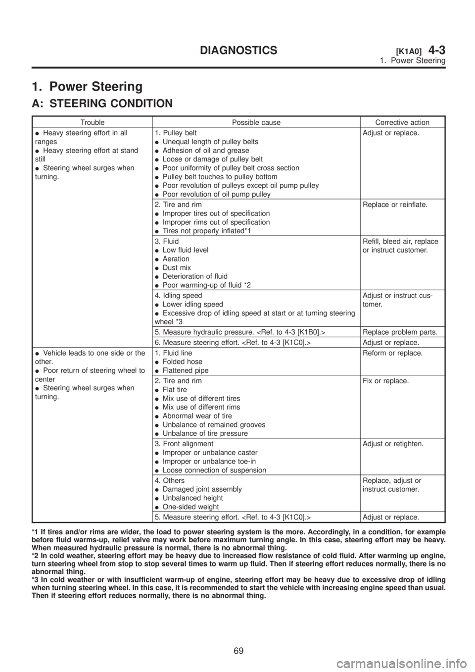
1. Power Steering
A: STEERING CONDITION
Trouble Possible cause Corrective action
IHeavy steering effort in all
ranges
IHeavy steering effort at stand
still
ISteering wheel surges when
turning.1. Pulley belt
IUnequal length of pulley belts
IAdhesion of oil and grease
ILoose or damage of pulley belt
IPoor uniformity of pulley belt cross section
IPulley belt touches to pulley bottom
IPoor revolution of pulleys except oil pump pulley
IPoor revolution of oil pump pulleyAdjust or replace.
2. Tire and rim
IImproper tires out of specification
IImproper rims out of specification
ITires not properly inflated*1Replace or reinflate.
3. Fluid
ILow fluid level
IAeration
IDust mix
IDeterioration of fluid
IPoor warming-up of fluid *2Refill, bleed air, replace
or instruct customer.
4. Idling speed
ILower idling speed
IExcessive drop of idling speed at start or at turning steering
wheel *3Adjust or instruct cus-
tomer.
5. Measure hydraulic pressure.
6. Measure steering effort.
IVehicle leads to one side or the
other.
IPoor return of steering wheel to
center
ISteering wheel surges when
turning.1. Fluid line
IFolded hose
IFlattened pipeReform or replace.
2. Tire and rim
IFlat tire
IMix use of different tires
IMix use of different rims
IAbnormal wear of tire
IUnbalance of remained grooves
IUnbalance of tire pressureFix or replace.
3. Front alignment
IImproper or unbalance caster
IImproper or unbalance toe-in
ILoose connection of suspensionAdjust or retighten.
4. Others
IDamaged joint assembly
IUnbalanced height
IOne-sided weightReplace, adjust or
instruct customer.
5. Measure steering effort.
*1 If tires and/or rims are wider, the load to power steering system is the more. Accordingly, in a condition, for example
before fluid warms-up, relief valve may work before maximum turning angle. In this case, steering effort may be heavy.
When measured hydraulic pressure is normal, there is no abnormal thing.
*2 In cold weather, steering effort may be heavy due to increased flow resistance of cold fluid. After warming up engine,
turn steering wheel from stop to stop several times to warm up fluid. Then if steering effort reduces normally, there is no
abnormal thing.
*3 In cold weather or with insufficient warm-up of engine, steering effort may be heavy due to excessive drop of idling
when turning steering wheel. In this case, it is recommended to start the vehicle with increasing engine speed than usual.
Then if steering effort reduces normally, there is no abnormal thing.
69
[K1A0]4-3DIAGNOSTICS
1. Power Steering
Page 944 of 1456

Trouble and possible cause Corrective action
In the case of the disc brake:
(1) Excessively worn pad or the support Replace the pad or the support.
In the case of the drum brake:
(1) Excessively worn shoe ridge Replace the back plate.
(2) Lack of oil on the shoe ridge surface and anchor Add more grease.
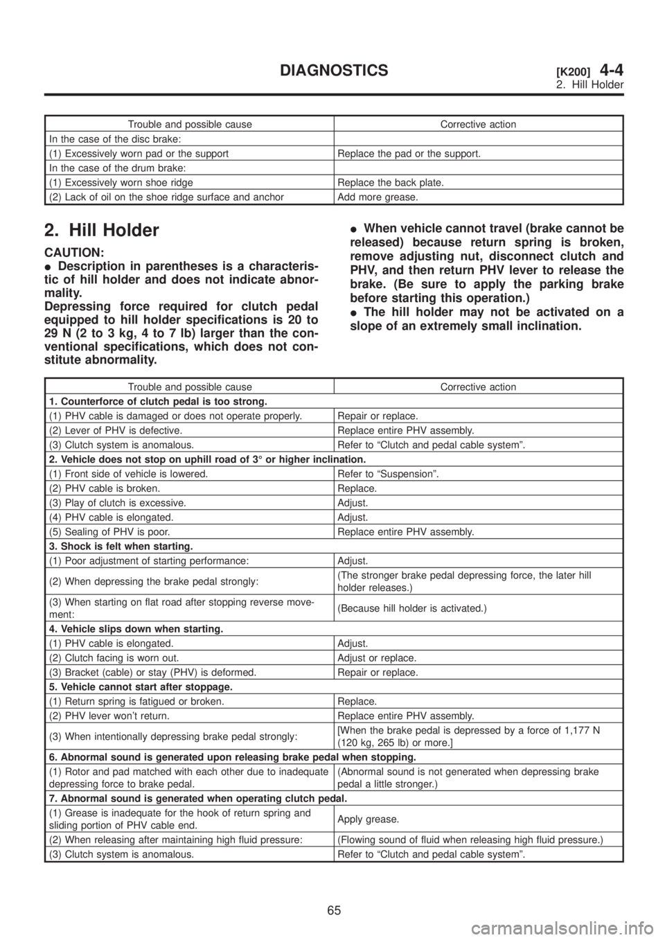
2. Hill Holder
CAUTION:
IDescription in parentheses is a characteris-
tic of hill holder and does not indicate abnor-
mality.
Depressing force required for clutch pedal
equipped to hill holder specifications is 20 to
29 N (2 to 3 kg, 4 to 7 lb) larger than the con-
ventional specifications, which does not con-
stitute abnormality.IWhen vehicle cannot travel (brake cannot be
released) because return spring is broken,
remove adjusting nut, disconnect clutch and
PHV, and then return PHV lever to release the
brake. (Be sure to apply the parking brake
before starting this operation.)
IThe hill holder may not be activated on a
slope of an extremely small inclination.
Trouble and possible cause Corrective action
1. Counterforce of clutch pedal is too strong.
(1) PHV cable is damaged or does not operate properly. Repair or replace.
(2) Lever of PHV is defective. Replace entire PHV assembly.
(3) Clutch system is anomalous. Refer to ªClutch and pedal cable systemº.
2. Vehicle does not stop on uphill road of 3É or higher inclination.
(1) Front side of vehicle is lowered. Refer to ªSuspensionº.
(2) PHV cable is broken. Replace.
(3) Play of clutch is excessive. Adjust.
(4) PHV cable is elongated. Adjust.
(5) Sealing of PHV is poor. Replace entire PHV assembly.
3. Shock is felt when starting.
(1) Poor adjustment of starting performance: Adjust.
(2) When depressing the brake pedal strongly:(The stronger brake pedal depressing force, the later hill
holder releases.)
(3) When starting on flat road after stopping reverse move-
ment:(Because hill holder is activated.)
4. Vehicle slips down when starting.
(1) PHV cable is elongated. Adjust.
(2) Clutch facing is worn out. Adjust or replace.
(3) Bracket (cable) or stay (PHV) is deformed. Repair or replace.
5. Vehicle cannot start after stoppage.
(1) Return spring is fatigued or broken. Replace.
(2) PHV lever won't return. Replace entire PHV assembly.
(3) When intentionally depressing brake pedal strongly:[When the brake pedal is depressed by a force of 1,177 N
(120 kg, 265 lb) or more.]
6. Abnormal sound is generated upon releasing brake pedal when stopping.
(1) Rotor and pad matched with each other due to inadequate
depressing force to brake pedal.(Abnormal sound is not generated when depressing brake
pedal a little stronger.)
7. Abnormal sound is generated when operating clutch pedal.
(1) Grease is inadequate for the hook of return spring and
sliding portion of PHV cable end.Apply grease.
(2) When releasing after maintaining high fluid pressure: (Flowing sound of fluid when releasing high fluid pressure.)
(3) Clutch system is anomalous. Refer to ªClutch and pedal cable systemº.
65
[K200]4-4DIAGNOSTICS
2. Hill Holder
Page 945 of 1456
Trouble and possible cause Corrective action
In the case of the disc brake:
(1) Excessively worn pad or the support Replace the pad or the support.
In the case of the drum brake:
(1) Excessively worn shoe ridge Replace the back plate.
(2) Lack of oil on the shoe ridge surface and anchor Add more grease.
2. Hill Holder
CAUTION:
IDescription in parentheses is a characteris-
tic of hill holder and does not indicate abnor-
mality.
Depressing force required for clutch pedal
equipped to hill holder specifications is 20 to
29 N (2 to 3 kg, 4 to 7 lb) larger than the con-
ventional specifications, which does not con-
stitute abnormality.IWhen vehicle cannot travel (brake cannot be
released) because return spring is broken,
remove adjusting nut, disconnect clutch and
PHV, and then return PHV lever to release the
brake. (Be sure to apply the parking brake
before starting this operation.)
IThe hill holder may not be activated on a
slope of an extremely small inclination.
Trouble and possible cause Corrective action
1. Counterforce of clutch pedal is too strong.
(1) PHV cable is damaged or does not operate properly. Repair or replace.
(2) Lever of PHV is defective. Replace entire PHV assembly.
(3) Clutch system is anomalous. Refer to ªClutch and pedal cable systemº.
2. Vehicle does not stop on uphill road of 3É or higher inclination.
(1) Front side of vehicle is lowered. Refer to ªSuspensionº.
(2) PHV cable is broken. Replace.
(3) Play of clutch is excessive. Adjust.
(4) PHV cable is elongated. Adjust.
(5) Sealing of PHV is poor. Replace entire PHV assembly.
3. Shock is felt when starting.
(1) Poor adjustment of starting performance: Adjust.
(2) When depressing the brake pedal strongly:(The stronger brake pedal depressing force, the later hill
holder releases.)
(3) When starting on flat road after stopping reverse move-
ment:(Because hill holder is activated.)
4. Vehicle slips down when starting.
(1) PHV cable is elongated. Adjust.
(2) Clutch facing is worn out. Adjust or replace.
(3) Bracket (cable) or stay (PHV) is deformed. Repair or replace.
5. Vehicle cannot start after stoppage.
(1) Return spring is fatigued or broken. Replace.
(2) PHV lever won't return. Replace entire PHV assembly.
(3) When intentionally depressing brake pedal strongly:[When the brake pedal is depressed by a force of 1,177 N
(120 kg, 265 lb) or more.]
6. Abnormal sound is generated upon releasing brake pedal when stopping.
(1) Rotor and pad matched with each other due to inadequate
depressing force to brake pedal.(Abnormal sound is not generated when depressing brake
pedal a little stronger.)
7. Abnormal sound is generated when operating clutch pedal.
(1) Grease is inadequate for the hook of return spring and
sliding portion of PHV cable end.Apply grease.
(2) When releasing after maintaining high fluid pressure: (Flowing sound of fluid when releasing high fluid pressure.)
(3) Clutch system is anomalous. Refer to ªClutch and pedal cable systemº.
65
[K200]4-4DIAGNOSTICS
2. Hill Holder
Page 982 of 1456
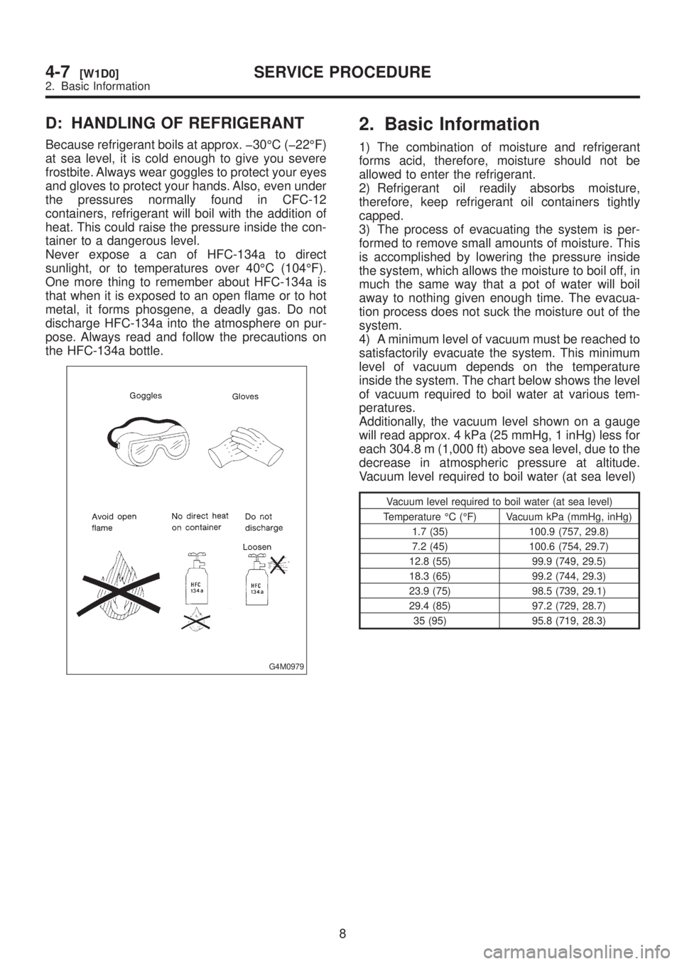
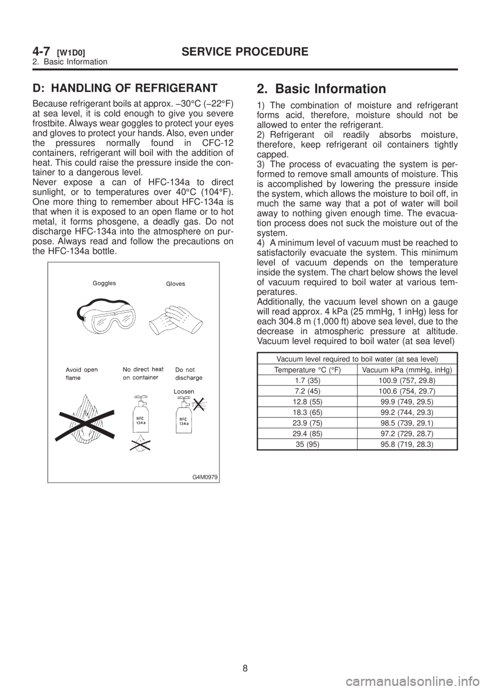
D: HANDLING OF REFRIGERANT
Because refrigerant boils at approx. þ30ÉC (þ22ÉF)
at sea level, it is cold enough to give you severe
frostbite. Always wear goggles to protect your eyes
and gloves to protect your hands. Also, even under
the pressures normally found in CFC-12
containers, refrigerant will boil with the addition of
heat. This could raise the pressure inside the con-
tainer to a dangerous level.
Never expose a can of HFC-134a to direct
sunlight, or to temperatures over 40ÉC (104ÉF).
One more thing to remember about HFC-134a is
that when it is exposed to an open flame or to hot
metal, it forms phosgene, a deadly gas. Do not
discharge HFC-134a into the atmosphere on pur-
pose. Always read and follow the precautions on
the HFC-134a bottle.
G4M0979
2. Basic Information
1) The combination of moisture and refrigerant
forms acid, therefore, moisture should not be
allowed to enter the refrigerant.
2) Refrigerant oil readily absorbs moisture,
therefore, keep refrigerant oil containers tightly
capped.
3) The process of evacuating the system is per-
formed to remove small amounts of moisture. This
is accomplished by lowering the pressure inside
the system, which allows the moisture to boil off, in
much the same way that a pot of water will boil
away to nothing given enough time. The evacua-
tion process does not suck the moisture out of the
system.
4) A minimum level of vacuum must be reached to
satisfactorily evacuate the system. This minimum
level of vacuum depends on the temperature
inside the system. The chart below shows the level
of vacuum required to boil water at various tem-
peratures.
Additionally, the vacuum level shown on a gauge
will read approx. 4 kPa (25 mmHg, 1 inHg) less for
each 304.8 m (1,000 ft) above sea level, due to the
decrease in atmospheric pressure at altitude.
Vacuum level required to boil water (at sea level)
Vacuum level required to boil water (at sea level)
Temperature ÉC (ÉF) Vacuum kPa (mmHg, inHg)
1.7 (35) 100.9 (757, 29.8)
7.2 (45) 100.6 (754, 29.7)
12.8 (55) 99.9 (749, 29.5)
18.3 (65) 99.2 (744, 29.3)
23.9 (75) 98.5 (739, 29.1)
29.4 (85) 97.2 (729, 28.7)
35 (95) 95.8 (719, 28.3)
8
4-7[W1D0]SERVICE PROCEDURE
2. Basic Information
Page 983 of 1456
D: HANDLING OF REFRIGERANT
Because refrigerant boils at approx. þ30ÉC (þ22ÉF)
at sea level, it is cold enough to give you severe
frostbite. Always wear goggles to protect your eyes
and gloves to protect your hands. Also, even under
the pressures normally found in CFC-12
containers, refrigerant will boil with the addition of
heat. This could raise the pressure inside the con-
tainer to a dangerous level.
Never expose a can of HFC-134a to direct
sunlight, or to temperatures over 40ÉC (104ÉF).
One more thing to remember about HFC-134a is
that when it is exposed to an open flame or to hot
metal, it forms phosgene, a deadly gas. Do not
discharge HFC-134a into the atmosphere on pur-
pose. Always read and follow the precautions on
the HFC-134a bottle.
G4M0979
2. Basic Information
1) The combination of moisture and refrigerant
forms acid, therefore, moisture should not be
allowed to enter the refrigerant.
2) Refrigerant oil readily absorbs moisture,
therefore, keep refrigerant oil containers tightly
capped.
3) The process of evacuating the system is per-
formed to remove small amounts of moisture. This
is accomplished by lowering the pressure inside
the system, which allows the moisture to boil off, in
much the same way that a pot of water will boil
away to nothing given enough time. The evacua-
tion process does not suck the moisture out of the
system.
4) A minimum level of vacuum must be reached to
satisfactorily evacuate the system. This minimum
level of vacuum depends on the temperature
inside the system. The chart below shows the level
of vacuum required to boil water at various tem-
peratures.
Additionally, the vacuum level shown on a gauge
will read approx. 4 kPa (25 mmHg, 1 inHg) less for
each 304.8 m (1,000 ft) above sea level, due to the
decrease in atmospheric pressure at altitude.
Vacuum level required to boil water (at sea level)
Vacuum level required to boil water (at sea level)
Temperature ÉC (ÉF) Vacuum kPa (mmHg, inHg)
1.7 (35) 100.9 (757, 29.8)
7.2 (45) 100.6 (754, 29.7)
12.8 (55) 99.9 (749, 29.5)
18.3 (65) 99.2 (744, 29.3)
23.9 (75) 98.5 (739, 29.1)
29.4 (85) 97.2 (729, 28.7)
35 (95) 95.8 (719, 28.3)
8
4-7[W1D0]SERVICE PROCEDURE
2. Basic Information
Page 995 of 1456
8. Leak Testing
A: INSPECTION
The following points should be kept in mind when
conducting a refrigerant leak test.
1) The A/C system to be tested must have an
adequate refrigerant charge to begin with.
2) The area where the leak test is conducted must
be free of wind and drafts, with still air being the
ideal condition.
3) The atmosphere where the leak test is con-
ducted must be free of refrigerant contamination.
4) Operate the A/C system for approx. 10 minutes,
then turn the engine off an begin the leak test.
5) Refrigerant gas is heavier than air, therefore
always hold the probe below the connection being
tested.
6) When checking for a leak along a length of
hose or tube, the leak detector probe must be
moved slowly, approx. 25 mm (1 in) per second
making sure probe does not come in contact with
the component being tested.
7) When checking for a leak at a certain point, the
leak detector probe must be held at that point for
at least 5 seconds.
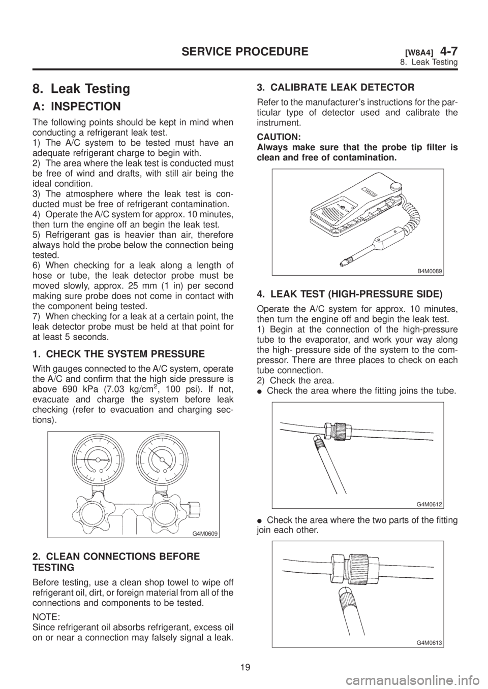
1. CHECK THE SYSTEM PRESSURE
With gauges connected to the A/C system, operate
the A/C and confirm that the high side pressure is
above 690 kPa (7.03 kg/cm
2, 100 psi). If not,
evacuate and charge the system before leak
checking (refer to evacuation and charging sec-
tions).
G4M0609
2. CLEAN CONNECTIONS BEFORE
TESTING
Before testing, use a clean shop towel to wipe off
refrigerant oil, dirt, or foreign material from all of the
connections and components to be tested.
NOTE:
Since refrigerant oil absorbs refrigerant, excess oil
on or near a connection may falsely signal a leak.
3. CALIBRATE LEAK DETECTOR
Refer to the manufacturer's instructions for the par-
ticular type of detector used and calibrate the
instrument.
CAUTION:
Always make sure that the probe tip filter is
clean and free of contamination.
B4M0089
4. LEAK TEST (HIGH-PRESSURE SIDE)
Operate the A/C system for approx. 10 minutes,
then turn the engine off and begin the leak test.
1) Begin at the connection of the high-pressure
tube to the evaporator, and work your way along
the high- pressure side of the system to the com-
pressor. There are three places to check on each
tube connection.
2) Check the area.
ICheck the area where the fitting joins the tube.
G4M0612
ICheck the area where the two parts of the fitting
join each other.
G4M0613
19
[W8A4]4-7SERVICE PROCEDURE
8. Leak Testing