Page 1223 of 1456

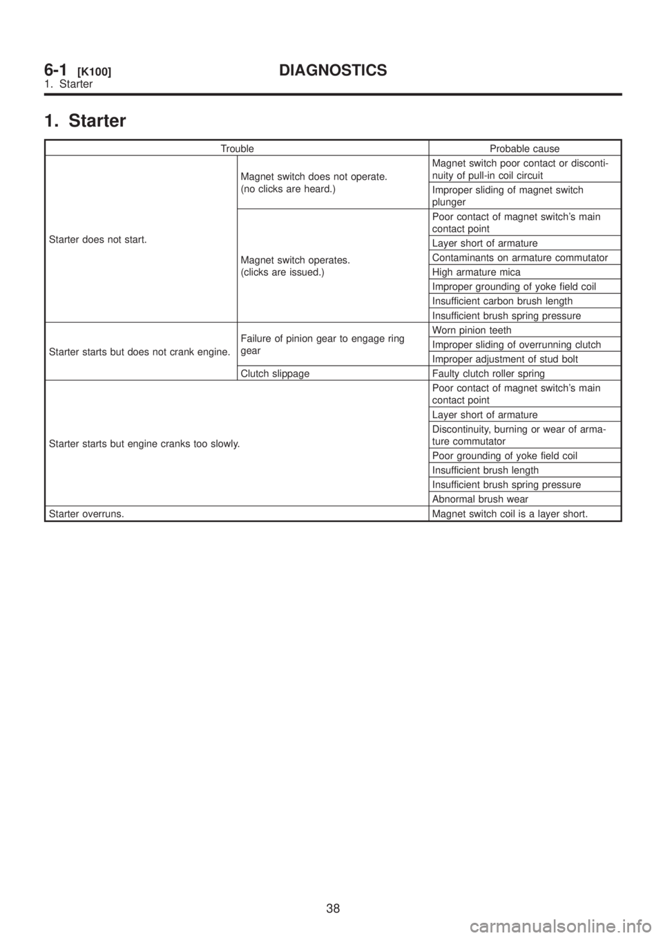
1. Starter
Trouble Probable cause
Starter does not start.Magnet switch does not operate.
(no clicks are heard.)Magnet switch poor contact or disconti-
nuity of pull-in coil circuit
Improper sliding of magnet switch
plunger
Magnet switch operates.
(clicks are issued.)Poor contact of magnet switch's main
contact point
Layer short of armature
Contaminants on armature commutator
High armature mica
Improper grounding of yoke field coil
Insufficient carbon brush length
Insufficient brush spring pressure
Starter starts but does not crank engine.Failure of pinion gear to engage ring
gearWorn pinion teeth
Improper sliding of overrunning clutch
Improper adjustment of stud bolt
Clutch slippage Faulty clutch roller spring
Starter starts but engine cranks too slowly.Poor contact of magnet switch's main
contact point
Layer short of armature
Discontinuity, burning or wear of arma-
ture commutator
Poor grounding of yoke field coil
Insufficient brush length
Insufficient brush spring pressure
Abnormal brush wear
Starter overruns. Magnet switch coil is a layer short.
38
6-1[K100]DIAGNOSTICS
1. Starter
Page 1226 of 1456

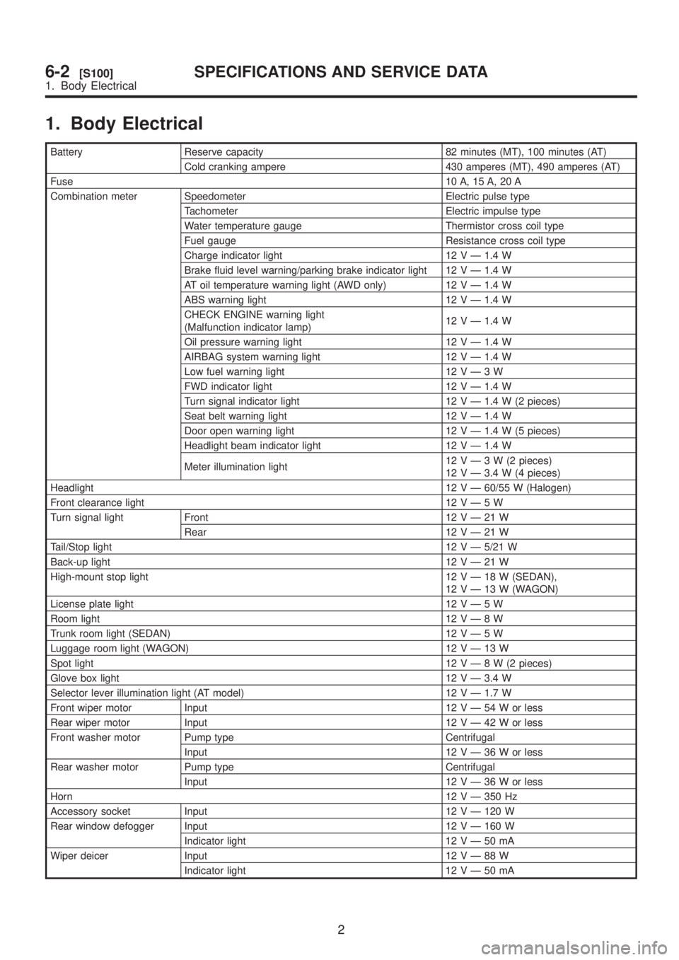
1. Body Electrical
Battery Reserve capacity 82 minutes (MT), 100 minutes (AT)
Cold cranking ampere 430 amperes (MT), 490 amperes (AT)
Fuse10 A, 15 A, 20 A
Combination meter Speedometer Electric pulse type
Tachometer Electric impulse type
Water temperature gauge Thermistor cross coil type
Fuel gauge Resistance cross coil type
Charge indicator light 12 V Ð 1.4 W
Brake fluid level warning/parking brake indicator light 12 V Ð 1.4 W
AT oil temperature warning light (AWD only) 12 V Ð 1.4 W
ABS warning light 12 V Ð 1.4 W
CHECK ENGINE warning light
(Malfunction indicator lamp)12 V Ð 1.4 W
Oil pressure warning light 12 V Ð 1.4 W
AIRBAG system warning light 12 V Ð 1.4 W
Low fuel warning light 12VÐ3W
FWD indicator light 12 V Ð 1.4 W
Turn signal indicator light 12 V Ð 1.4 W (2 pieces)
Seat belt warning light 12 V Ð 1.4 W
Door open warning light 12 V Ð 1.4 W (5 pieces)
Headlight beam indicator light 12 V Ð 1.4 W
Meter illumination light12VÐ3W(2pieces)
12 V Ð 3.4 W (4 pieces)
Headlight12 V Ð 60/55 W (Halogen)
Front clearance light 12VÐ5W
Turn signal light Front 12VÐ21W
Rear 12VÐ21W
Tail/Stop light12 V Ð 5/21 W
Back-up light12VÐ21W
High-mount stop light 12VÐ18W(SEDAN),
12VÐ13W(WAGON)
License plate light 12VÐ5W
Room light12VÐ8W
Trunk room light (SEDAN) 12VÐ5W
Luggage room light (WAGON) 12VÐ13W
Spot light12VÐ8W(2pieces)
Glove box light 12 V Ð 3.4 W
Selector lever illumination light (AT model) 12 V Ð 1.7 W
Front wiper motor Input 12VÐ54Worless
Rear wiper motor Input 12VÐ42Worless
Front washer motor Pump type Centrifugal
Input 12VÐ36Worless
Rear washer motor Pump type Centrifugal
Input 12VÐ36Worless
Horn12 V Ð 350 Hz
Accessory socket Input 12 V Ð 120 W
Rear window defogger Input 12 V Ð 160 W
Indicator light 12VÐ50mA
Wiper deicer Input 12VÐ88W
Indicator light 12VÐ50mA
2
6-2[S100]SPECIFICATIONS AND SERVICE DATA
1. Body Electrical
Page 1231 of 1456

4. Headlight
A: ADJUSTMENT
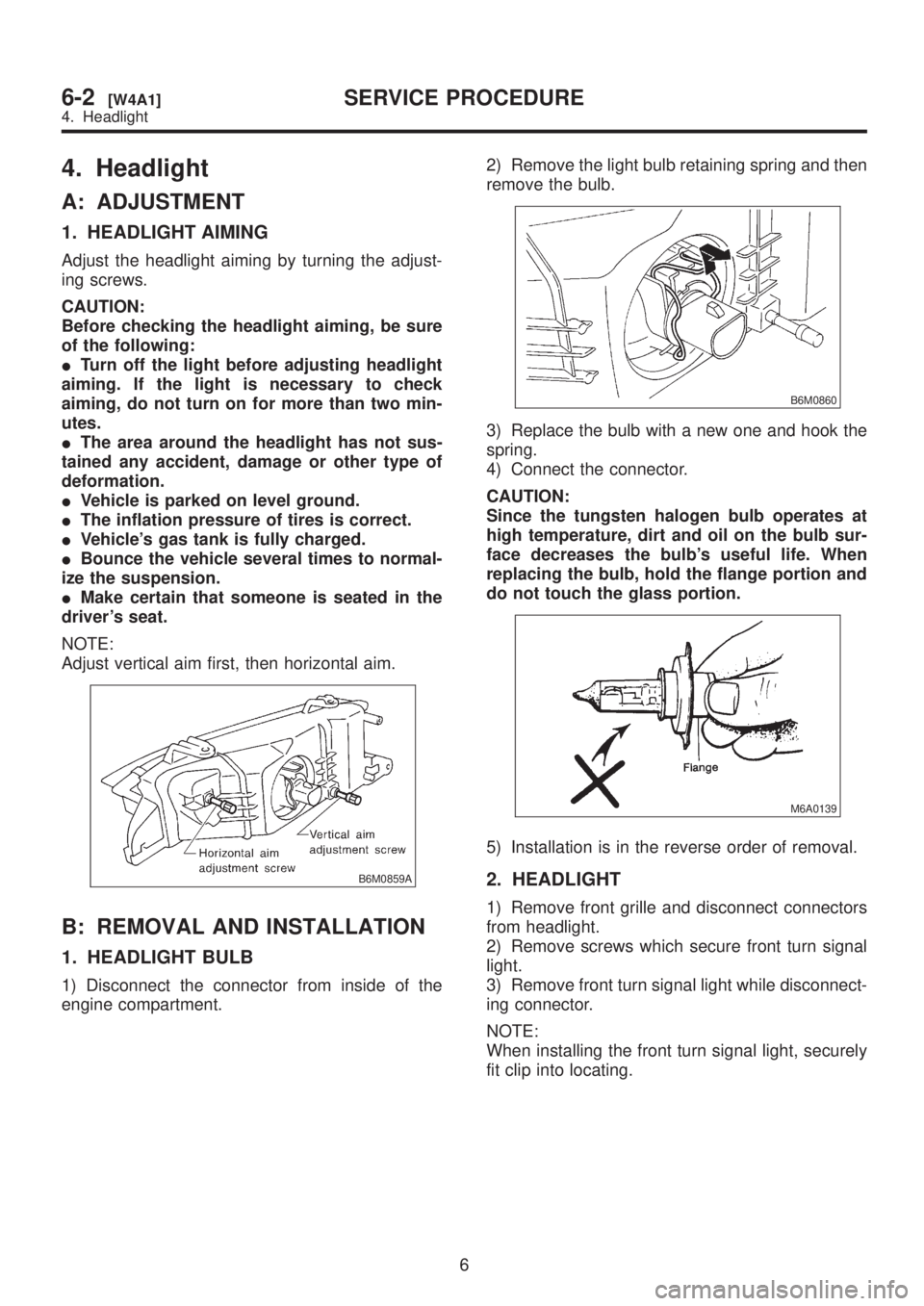
1. HEADLIGHT AIMING
Adjust the headlight aiming by turning the adjust-
ing screws.
CAUTION:
Before checking the headlight aiming, be sure
of the following:
ITurn off the light before adjusting headlight
aiming. If the light is necessary to check
aiming, do not turn on for more than two min-
utes.
IThe area around the headlight has not sus-
tained any accident, damage or other type of
deformation.
IVehicle is parked on level ground.
IThe inflation pressure of tires is correct.
IVehicle's gas tank is fully charged.
IBounce the vehicle several times to normal-
ize the suspension.
IMake certain that someone is seated in the
driver's seat.
NOTE:
Adjust vertical aim first, then horizontal aim.
B6M0859A
B: REMOVAL AND INSTALLATION
1. HEADLIGHT BULB
1) Disconnect the connector from inside of the
engine compartment.2) Remove the light bulb retaining spring and then
remove the bulb.
B6M0860
3) Replace the bulb with a new one and hook the
spring.
4) Connect the connector.
CAUTION:
Since the tungsten halogen bulb operates at
high temperature, dirt and oil on the bulb sur-
face decreases the bulb's useful life. When
replacing the bulb, hold the flange portion and
do not touch the glass portion.
M6A0139
5) Installation is in the reverse order of removal.
2. HEADLIGHT
1) Remove front grille and disconnect connectors
from headlight.
2) Remove screws which secure front turn signal
light.
3) Remove front turn signal light while disconnect-
ing connector.
NOTE:
When installing the front turn signal light, securely
fit clip into locating.
6
6-2[W4A1]SERVICE PROCEDURE
4. Headlight
Page 1256 of 1456
B: BULB REPLACEMENT
B6M0761C
(1) Tachometer and temperature
gauge illumination
(2) Oil pressure
(3) CHECK ENGINE (Malfunction
Indicator Light)
(4) Tachometer illumination
(5) Turn signal (RH)
(6) Headlight beam(7) Door open (Front-Right)
(8) Seat belt
(9) Door open (Front-Left)
(10) Door open (Rear-Right)
(11) Door open (Rear-Left)
(12) Rear gate open (Wagon)
(13) Turn signal (LH)
(14) Speedometer illumination(15) Speedometer and fuel gauge
illumination
(16) Low fuel
(17) Charge
(18) Brake fluid level/parking brake
(19) FWD
(20) AT oil temperature
(21) ABS
28
6-2[W14B0]SERVICE PROCEDURE
14. Combination Meter
Page 1413 of 1456
![SUBARU LEGACY 1999 Service Repair Manual 7. Electrical Unit Location
A: LIST
Electrical unit Index No.
ABS control module <Ref. to 4-4 [T300].>
ABS G sensor (MT) <Ref. to 4-4 [T300].>
A/C compressor relay <Ref. to 6-3 [D7B1].>
A/C fuse <Ref. SUBARU LEGACY 1999 Service Repair Manual 7. Electrical Unit Location
A: LIST
Electrical unit Index No.
ABS control module <Ref. to 4-4 [T300].>
ABS G sensor (MT) <Ref. to 4-4 [T300].>
A/C compressor relay <Ref. to 6-3 [D7B1].>
A/C fuse <Ref.](/manual-img/17/57435/w960_57435-1412.png)
7. Electrical Unit Location
A: LIST
Electrical unit Index No.
ABS control module
ABS G sensor (MT)
A/C compressor relay
A/C fuse
A/C main fan relay 1
A/C main fan relay 2
A/C pressure switch
A/C sub fan relay 2
ATF temperature sensor
Blower motor resistor
Blower relay
Camshaft position sensor
Check connector
Clutch switch (MT)
Crankshaft position sensor
Cruise control module
Cruise control pump
Data link connector (for
OBD-II G.S.T.)
Data link connector (for
S.S.M.)
Diagnosis connector
Diagnosis terminal (Ground)
Door lock timer
Engine control module
Engine coolant temperature
sensor
Engine hood switch (Secu-
rity)
Evaporator thermoswitch
F/B
FRESH/RECIRC actuator
Fuel pump relay
Fuel gauge module
Fuel gauge sub module
(AWD)
FWD switch (AT)
Headlight alarm relay
(Security)
Headlight relay LH
Electrical unit Index No.
Headlight relay RH
Horn relay
Hydraulic unit (ABS)
Ignition coil
Ignitor
Idle air control solenoid
valve
Illumination control module
Inhibitor switch
Knock sensor
Main fan relay
Main relay
Mass air flow sensor
Mode actuator
M/B
Oil pressure switch
Oxygen sensor
Pedal stroke sensor (TCS)
Power window and sunroof
relay
Power window circuit
breaker
Purge control solenoid valve
Rear defogger relay
Seat belt timer
Security control module
Shift lock control module
Starter interrupt relay (Secu-
rity)
Stop & brake switch (With
cruise control)
Sunroof control module
Tail and illumination relay
TCS control module
TCS motor relay
TCS valve relay
Throttle position sensor
Test mode connector
Transmission control mod-
ule
Turn & hazard module
Vehicle speed sensor 1
Vehicle speed sensor 2
133
[D7A0]6-3WIRING DIAGRAM
7. Electrical Unit Location
Page 1434 of 1456

E: ENGINE WIRING HARNESS AND TRANSMISSION CORD
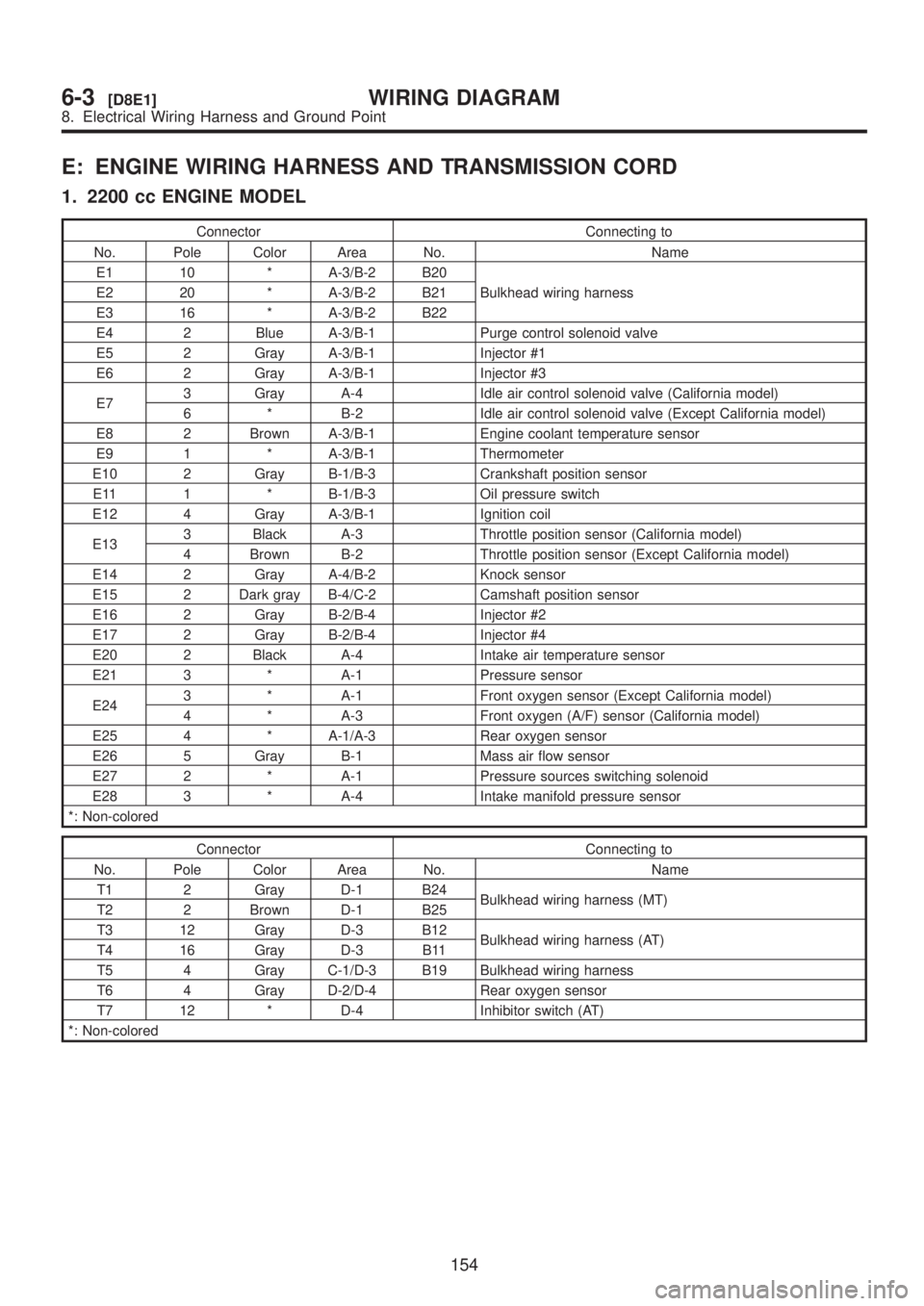
1. 2200 cc ENGINE MODEL
Connector Connecting to
No. Pole Color Area No. Name
E1 10 * A-3/B-2 B20
Bulkhead wiring harness E2 20 * A-3/B-2 B21
E3 16 * A-3/B-2 B22
E4 2 Blue A-3/B-1 Purge control solenoid valve
E5 2 Gray A-3/B-1 Injector #1
E6 2 Gray A-3/B-1 Injector #3
E73 Gray A-4 Idle air control solenoid valve (California model)
6 * B-2 Idle air control solenoid valve (Except California model)
E8 2 Brown A-3/B-1 Engine coolant temperature sensor
E9 1 * A-3/B-1 Thermometer
E10 2 Gray B-1/B-3 Crankshaft position sensor
E11 1 * B-1/B-3 Oil pressure switch
E12 4 Gray A-3/B-1 Ignition coil
E133 Black A-3 Throttle position sensor (California model)
4 Brown B-2 Throttle position sensor (Except California model)
E14 2 Gray A-4/B-2 Knock sensor
E15 2 Dark gray B-4/C-2 Camshaft position sensor
E16 2 Gray B-2/B-4 Injector #2
E17 2 Gray B-2/B-4 Injector #4
E20 2 Black A-4 Intake air temperature sensor
E21 3 * A-1 Pressure sensor
E243 * A-1 Front oxygen sensor (Except California model)
4 * A-3 Front oxygen (A/F) sensor (California model)
E25 4 * A-1/A-3 Rear oxygen sensor
E26 5 Gray B-1 Mass air flow sensor
E27 2 * A-1 Pressure sources switching solenoid
E28 3 * A-4 Intake manifold pressure sensor
*: Non-colored
Connector Connecting to
No. Pole Color Area No. Name
T1 2 Gray D-1 B24
Bulkhead wiring harness (MT)
T2 2 Brown D-1 B25
T3 12 Gray D-3 B12
Bulkhead wiring harness (AT)
T4 16 Gray D-3 B11
T5 4 Gray C-1/D-3 B19 Bulkhead wiring harness
T6 4 Gray D-2/D-4 Rear oxygen sensor
T7 12 * D-4 Inhibitor switch (AT)
*: Non-colored
154
6-3[D8E1]WIRING DIAGRAM
8. Electrical Wiring Harness and Ground Point