Page 368 of 1456
1. On-car Services
A: PRECAUTIONS
WARNING:
IPlace ªNo fireº signs near the working area.
IDisconnect ground terminal from battery.
IBe careful not to spill fuel on the floor.
B: RELEASING OF FUEL
PRESSURE
1) Take off floor mat.
2) Remove access hole lid.
G2M0340
3) Disconnect connector from fuel pump.
B2M0047
4) Start the engine, and run it until it stalls.
5) After the engine stalls, crank it for five more
seconds.
6) Turn ignition switch OFF.
C: DRAINING OF FUEL
1) Remove rear seat and seat back.2) Remove access hole lid.
G2M0340
3) Disconnect connector from fuel pump.
B2M0047
4) Release fuel pressure.
5) Disconnect fuel delivery hose (A), return hose
(B) and jet pump hose (C).
B2M0048B
6) Remove nuts which install fuel pump assembly
onto fuel tank.
G2M0343
7
[W1C0]2-8SERVICE PROCEDURE
1. On-car Services
Page 369 of 1456
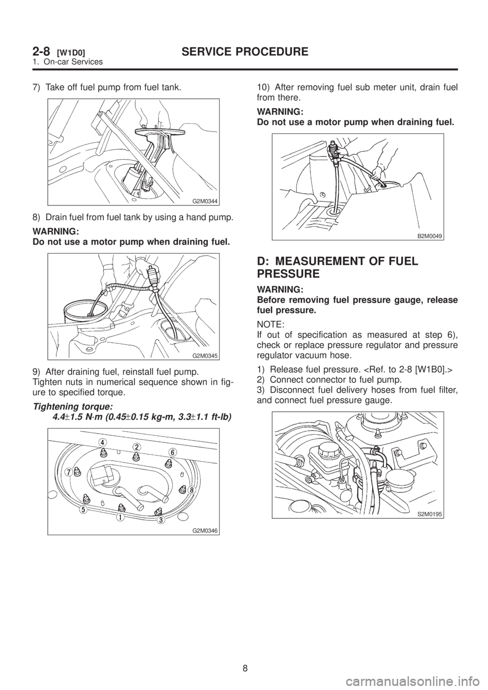
7) Take off fuel pump from fuel tank.
G2M0344
8) Drain fuel from fuel tank by using a hand pump.
WARNING:
Do not use a motor pump when draining fuel.
G2M0345
9) After draining fuel, reinstall fuel pump.
Tighten nuts in numerical sequence shown in fig-
ure to specified torque.
Tightening torque:
4.4
±1.5 N´m (0.45±0.15 kg-m, 3.3±1.1 ft-lb)
G2M0346
10) After removing fuel sub meter unit, drain fuel
from there.
WARNING:
Do not use a motor pump when draining fuel.
B2M0049
D: MEASUREMENT OF FUEL
PRESSURE
WARNING:
Before removing fuel pressure gauge, release
fuel pressure.
NOTE:
If out of specification as measured at step 6),
check or replace pressure regulator and pressure
regulator vacuum hose.
1) Release fuel pressure.
2) Connect connector to fuel pump.
3) Disconnect fuel delivery hoses from fuel filter,
and connect fuel pressure gauge.
S2M0195
8
2-8[W1D0]SERVICE PROCEDURE
1. On-car Services
Page 374 of 1456
20) Remove rear crossmember.
G4M0545
21) Remove two evaporation hoses from holding
clip.
B2M1744A
22) Loosen clamp, and disconnect fuel filler hose.
B2M1745
23) Loosen clamp, and then disconnect fuel deliv-
ery hose (A).
24) Move clips, and disconnect fuel return hose
(B) and evaporation hose (C).
B2M0310B
25) While holding fuel tank, remove bolts from
bands and dismount fuel tank.
WARNING:
A helper is required to perform this work.
S2M0169A
B: INSTALLATION
1) While a helper holds fuel tank, push fuel tank
harness into access hole with grommet.
2) Set fuel tank, and temporary tighten bolts for
installing fuel tank bands.
S2M0169A
3) Connect fuel filler hose, and tighten clamp.
B2M1745
4) Install two evaporation hoses to holding clip.
12
2-8[W2B0]SERVICE PROCEDURE
2. Fuel Tank
Page 385 of 1456

B: INSPECTION
Connect lead harness to connector terminal of fuel
pump, and apply battery power supply to check
whether the pump operate.
WARNING:
IWipe off the fuel completely.
IKeep battery as far apart from fuel pump as
possible.
IBe sure to turn the battery supply ON and
OFF on the battery side.
IDo not run fuel pump for a long time under
non-load condition.
G2M0366
C: INSTALLATION
Installation is in the reverse order of removal. Do
the following:
(1) Always use new gaskets.
(2) Ensure sealing portion is free from fuel or for-
eign particles before installation.
(3) Tighten nuts in numerical sequence shown in
Figure to specified torque.
Tightening torque:
4.4
±1.5 N´m (0.45±0.15 kg-m, 3.3±1.1 ft-lb)
G2M0346
6. Fuel Meter Unit
A: REMOVAL
NOTE:
Fuel meter unit is built in fuel pump assembly.
1) Release fuel pressure.
2) Disconnect fuel delivery hose (A), return hose
(B) and jet pump hose (C) (AWD model only).
B2M0048B
3) Remove nuts which install fuel pump assembly
onto fuel tank.
4) Take off fuel pump assembly.
G2M0344
22
2-8[W5B0]SERVICE PROCEDURE
6. Fuel Meter Unit
Page 386 of 1456

B: INSPECTION
Connect lead harness to connector terminal of fuel
pump, and apply battery power supply to check
whether the pump operate.
WARNING:
IWipe off the fuel completely.
IKeep battery as far apart from fuel pump as
possible.
IBe sure to turn the battery supply ON and
OFF on the battery side.
IDo not run fuel pump for a long time under
non-load condition.
G2M0366
C: INSTALLATION
Installation is in the reverse order of removal. Do
the following:
(1) Always use new gaskets.
(2) Ensure sealing portion is free from fuel or for-
eign particles before installation.
(3) Tighten nuts in numerical sequence shown in
Figure to specified torque.
Tightening torque:
4.4
±1.5 N´m (0.45±0.15 kg-m, 3.3±1.1 ft-lb)
G2M0346
6. Fuel Meter Unit
A: REMOVAL
NOTE:
Fuel meter unit is built in fuel pump assembly.
1) Release fuel pressure.
2) Disconnect fuel delivery hose (A), return hose
(B) and jet pump hose (C) (AWD model only).
B2M0048B
3) Remove nuts which install fuel pump assembly
onto fuel tank.
4) Take off fuel pump assembly.
G2M0344
22
2-8[W5B0]SERVICE PROCEDURE
6. Fuel Meter Unit
Page 648 of 1456
E: INSTALLATION
1) Mount the selector lever onto the vehicle body.
2) Tighten the six bolts to install the selector lever
to the vehicle body, then connect connectors.
Tightening torque:
5.9
±1.5 N´m (0.6±0.15 kg-m, 4.3±1.1 ft-lb)
S3M0017A
3) Install console box.
4) Set location of selector lever at ªNº position.
5) Set location of selector arm installed on the
transmission body at ªNº position.
G3M0715
6) Pass inner cable through selector arm pin and
then connect it using a washer and snap pin.
7) Attach outer cable to plate on transmission
case with the bolts.
Tightening torque:
14
±4 N´m (1.4±0.4 kg-m, 10.1±2.9 ft-lb)
S3M0016A
8) Insert the thread portion of the other inner cable
and into the connector hole of the selector lever,
and fix the other outer cable end to the bracket.
9) Adjust the inner cable length.
(1) Put connector into contact with nut (A).
(2) Tighten nut (B).
Tightening torque:
7.4
±2.0 N´m (0.75±0.2 kg-m, 5.4±1.4 ft-lb)
S3M0019A
10) After completion of fitting, make sure that the
selector lever operates smoothly all across the
operating range.
11) Connect the harnesses and check the follow-
ing items.
(1) The engine starts operating when selector
lever is in position ªPº, but not in other positions.
(2) The back-up light is lit when the selector
lever is in position ªRº, but not in other positions.
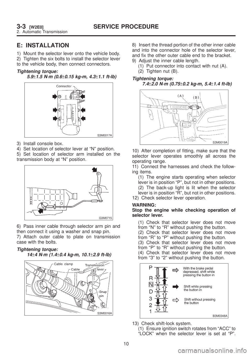
12) Check selector lever operation.
WARNING:
Stop the engine while checking operation of
selector lever.
(1) Check that selector lever does not move
from ªNº to ªRº without pushing the button.
(2) Check that selector lever does not move
from ªRº to ªPº without pushing the button.
(3) Check that selector lever does not move
from ªPº to ªRº without pushing the button.
(4) Check that selector lever does not move
from ª3º to ª2º without pushing the button.
B3M0348A
13) Check shift-lock system.
(1) Ensure ignition switch rotates from ªACCº to
ªLOCKº when the selector lever is set at ªPº.
10
3-3[W2E0]SERVICE PROCEDURE
2. Automatic Transmission
Page 801 of 1456
1. Supplemental Restraint
System ªAirbagº
A: PRECAUTION
Airbag system wiring harness is routed near the
steering wheel, steering shaft and column.
WARNING:
IAll Airbag system wiring harness and con-
nectors are colored yellow. Do not use electri-cal test equipment on these circuit.
IBe careful not to damage Airbag system wir-
ing harness when servicing the steering wheel,
steering shaft and column.
10
4-3[W1A0]SERVICE PROCEDURE
1. Supplemental Restraint System ªAirbagº
Page 802 of 1456
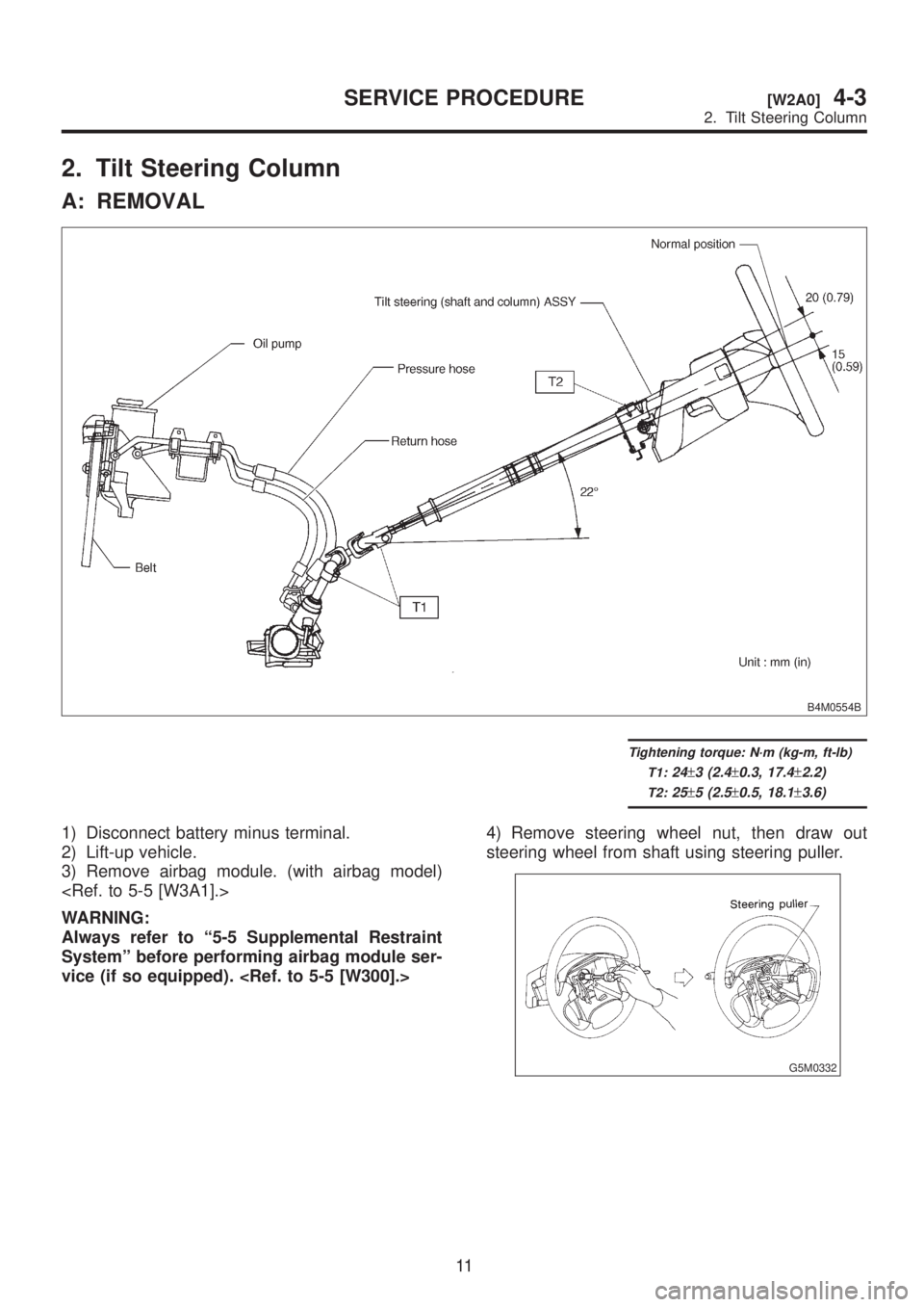
2. Tilt Steering Column
A: REMOVAL
B4M0554B
Tightening torque: N´m (kg-m, ft-lb)
T1:
24±3 (2.4±0.3, 17.4±2.2)
T2:25±5 (2.5±0.5, 18.1±3.6)
1) Disconnect battery minus terminal.
2) Lift-up vehicle.
3) Remove airbag module. (with airbag model)
WARNING:
Always refer to ª5-5 Supplemental Restraint
Systemº before performing airbag module ser-
vice (if so equipped). 4) Remove steering wheel nut, then draw out
steering wheel from shaft using steering puller.
G5M0332
11
[W2A0]4-3SERVICE PROCEDURE
2. Tilt Steering Column