1999 SUBARU LEGACY Ignition plug
[x] Cancel search: Ignition plugPage 33 of 1456
1. Foreword
A: GENERAL
This chapter describes major inspection and ser-
vice procedures for the engine mounted on the
body. For procedures not found in this chapter,
refer to the service procedure section in the appli-
cable chapter.
2. Ignition Timing
A: MEASUREMENT
CAUTION:
After warming-up, engine becomes very hot.
Be careful not to burn yourself during mea-
surement.
1) Warm-up the engine.
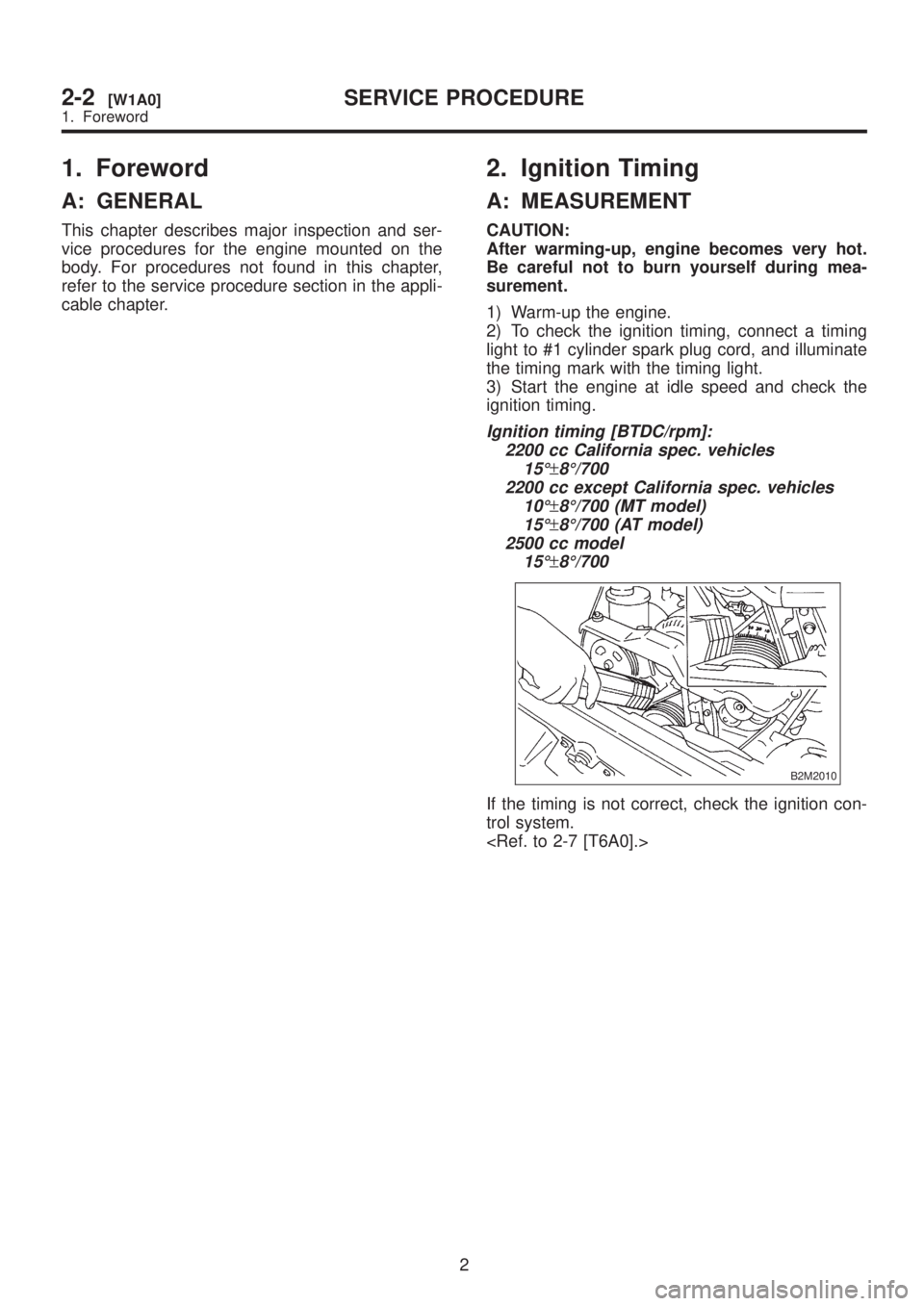
2) To check the ignition timing, connect a timing
light to #1 cylinder spark plug cord, and illuminate
the timing mark with the timing light.
3) Start the engine at idle speed and check the
ignition timing.
Ignition timing [BTDC/rpm]:
2200 cc California spec. vehicles
15É
±8É/700
2200 cc except California spec. vehicles
10É
±8É/700 (MT model)
15É
±8É/700 (AT model)
2500 cc model
15É
±8É/700
B2M2010
If the timing is not correct, check the ignition con-
trol system.
2
2-2[W1A0]SERVICE PROCEDURE
1. Foreword
Page 34 of 1456

1. Foreword
A: GENERAL
This chapter describes major inspection and ser-
vice procedures for the engine mounted on the
body. For procedures not found in this chapter,
refer to the service procedure section in the appli-
cable chapter.
2. Ignition Timing
A: MEASUREMENT
CAUTION:
After warming-up, engine becomes very hot.
Be careful not to burn yourself during mea-
surement.
1) Warm-up the engine.
2) To check the ignition timing, connect a timing
light to #1 cylinder spark plug cord, and illuminate
the timing mark with the timing light.
3) Start the engine at idle speed and check the
ignition timing.
Ignition timing [BTDC/rpm]:
2200 cc California spec. vehicles
15É
±8É/700
2200 cc except California spec. vehicles
10É
±8É/700 (MT model)
15É
±8É/700 (AT model)
2500 cc model
15É
±8É/700
B2M2010
If the timing is not correct, check the ignition con-
trol system.
2
2-2[W1A0]SERVICE PROCEDURE
1. Foreword
Page 35 of 1456

3. Engine Idle Speed
A: MEASUREMENT
1) Before checking idle speed, check the follow-
ing:
(1) Ensure that air cleaner element is free from
clogging, ignition timing is correct, spark plugs
are in good condition, and that hoses are con-
nected properly.
(2) Ensure that malfunction indicator light
(CHECK ENGINE light) does not illuminate.
2) Warm-up the engine.
3) Stop the engine, and turn ignition switch to
OFF.
4) When using SUBARU SELECT MONITOR;
NOTE:
For detailed operation procedures, refer to the
SUBARU SELECT MONITOR OPERATION
MANUAL.
(1) Insert the cartridge to SUBARU SELECT
MONITOR.
ST 24082AA090 CARTRIDGE
S2M0286A
(2) Connect SUBARU SELECT MONITOR to
the data link connector.
(3) Turn ignition switch to ON, and SUBARU
SELECT MONITOR switch to ON.
(4) Select {2. Each System Check} in Main
Menu.
(5) Select {EGI/EMPI} in Selection Menu.
(6) Select {1. Current Data Display & Save} in
EGI/EMPI Diagnosis.
(7) Select {1.12 Data Display} in Data Display
Menu.(8) Start the engine, and read engine idle
speed.
S2M0098
5) When using tachometer (Secondary pick-up
type).
(1) Attach the pick-up clip to No. 1 cylinder
spark plug cord.
(2) Start the engine, and read engine idle
speed.
B2M2011
NOTE:
IWhen using the OBD-II general scan tool, care-
fully read its operation manual.
IThis ignition system provides simultaneous igni-
tion for #1 and #2 plugs. It must be noted that
some tachometers may register twice that of actual
engine speed.
6) Check idle speed when unloaded. (With
headlights, heater fan, rear defroster, radiator fan,
air conditioning, etc. OFF)
Idle speed (No load and gears in neutral (MT),
or N or P (AT) position):
700
±100 rpm
7) Check idle speed when loaded. (Turn air con-
ditioning switch to |P¢rdquo;ON|P'ldquo; and oper-
ate compressor for at least one minute before
measurement.)
Idle speed [A/C ªONº, no load and gears in
neutral (MT) or N or P (AT) position]:
850
±50 rpm
3
[W3A0]2-2SERVICE PROCEDURE
3. Engine Idle Speed
Page 36 of 1456
![SUBARU LEGACY 1999 Service Repair Manual CAUTION:
Never rotate idle adjusting screw. If idle speed
is out of specifications, refer to General On-
board Diagnosis Table under ª2-7 On-Board
Diagnostics II Systemº.
<Ref. to 2-7 [T6A0].>4. Eng](/manual-img/17/57435/w960_57435-35.png "SUBARU LEGACY 1999 Service Repair Manual CAUTION:
Never rotate idle adjusting screw. If idle speed
is out of specifications, refer to General On-
board Diagnosis Table under ª2-7 On-Board
Diagnostics II Systemº.
<Ref. to 2-7 [T6A0].>4. Eng")
CAUTION:
Never rotate idle adjusting screw. If idle speed
is out of specifications, refer to General On-
board Diagnosis Table under ª2-7 On-Board
Diagnostics II Systemº.
A: MEASUREMENT
1. 2200 cc MODEL
1) After warming-up the engine, turn ignition
switch to OFF.
2) Make sure that the battery is fully charged.
3) Remove all the spark plugs.
4) Disconnect connectors from fuel injectors.
5) Fully open throttle valve.
6) Check the starter motor for satisfactory perfor-
mance and operation.
7) Hold the compression gauge tight against the
spark plug hole.
CAUTION:
When using a screw-in type compression
gauge, the screw (put into cylinder head spark
plug hole) should be less than 18 mm (0.71 in)
long.
8) Crank the engine by means of the starter motor,
and read the maximum value on the gauge when
the pointer is steady.
G2M0098
9) Perform at least two measurements per
cylinder, and make sure that the values are correct.
Compression (200 Ð 300 rpm and fully open
throttle):
Standard;
1,079 Ð 1,275 kPa (11.0 Ð 13.0 kg/cm
2,
156 Ð 185 psi)
Limit;
883 kPa (9.0 kg/cm
2, 128 psi)
Difference between cylinders;
196 kPa (2.0 kg/cm
2, 28 psi)
4
2-2[W4A1]SERVICE PROCEDURE
4. Engine Compression
Page 37 of 1456
![SUBARU LEGACY 1999 Service Repair Manual CAUTION:
Never rotate idle adjusting screw. If idle speed
is out of specifications, refer to General On-
board Diagnosis Table under ª2-7 On-Board
Diagnostics II Systemº.
<Ref. to 2-7 [T6A0].>4. Eng](/manual-img/17/57435/w960_57435-36.png "SUBARU LEGACY 1999 Service Repair Manual CAUTION:
Never rotate idle adjusting screw. If idle speed
is out of specifications, refer to General On-
board Diagnosis Table under ª2-7 On-Board
Diagnostics II Systemº.
<Ref. to 2-7 [T6A0].>4. Eng")
CAUTION:
Never rotate idle adjusting screw. If idle speed
is out of specifications, refer to General On-
board Diagnosis Table under ª2-7 On-Board
Diagnostics II Systemº.
A: MEASUREMENT
1. 2200 cc MODEL
1) After warming-up the engine, turn ignition
switch to OFF.
2) Make sure that the battery is fully charged.
3) Remove all the spark plugs.
4) Disconnect connectors from fuel injectors.
5) Fully open throttle valve.
6) Check the starter motor for satisfactory perfor-
mance and operation.
7) Hold the compression gauge tight against the
spark plug hole.
CAUTION:
When using a screw-in type compression
gauge, the screw (put into cylinder head spark
plug hole) should be less than 18 mm (0.71 in)
long.
8) Crank the engine by means of the starter motor,
and read the maximum value on the gauge when
the pointer is steady.
G2M0098
9) Perform at least two measurements per
cylinder, and make sure that the values are correct.
Compression (200 Ð 300 rpm and fully open
throttle):
Standard;
1,079 Ð 1,275 kPa (11.0 Ð 13.0 kg/cm
2,
156 Ð 185 psi)
Limit;
883 kPa (9.0 kg/cm
2, 128 psi)
Difference between cylinders;
196 kPa (2.0 kg/cm
2, 28 psi)
4
2-2[W4A1]SERVICE PROCEDURE
4. Engine Compression
Page 38 of 1456
2. 2500 cc MODEL
CAUTION:
After warming-up, engine becomes very hot.
Be careful not to burn yourself during mea-
surement.
1) After warming-up the engine, turn ignition
switch to OFF.
2) Make sure that the battery is fully charged.
3) Remove all the spark plugs.
4) Disconnect connectors from fuel injectors.
5) Fully open throttle valve.
6) Check the starter motor for satisfactory perfor-
mance and operation.
7) Hold the compression gauge tight against the
spark plug hole.
CAUTION:
When using a screw-in type compression
gauge, the screw (put into cylinder head spark
plug hole) should be less than 18 mm (0.71 in)
long.
8) Crank the engine by means of the starter motor,
and read the maximum value on the gauge when
the pointer is steady.
B2M0752A
9) Perform at least two measurements per
cylinder, and make sure that the values are correct.
Compression (350 rpm and fully open
throttle):
Standard;
1,216 kPa (12.4 kg/cm
2, 176 psi)
Limit;
941 kPa (9.6 kg/cm
2, 137 psi)
Difference between cylinders;
49 kPa (0.5 kg/cm
2, 7 psi), or less
5. Intake Manifold Vacuum
A: MEASUREMENT
1) Warm-up the engine.
2) Disconnect the brake vacuum hose and install
the vacuum gauge to the hose fitting on the mani-
fold.
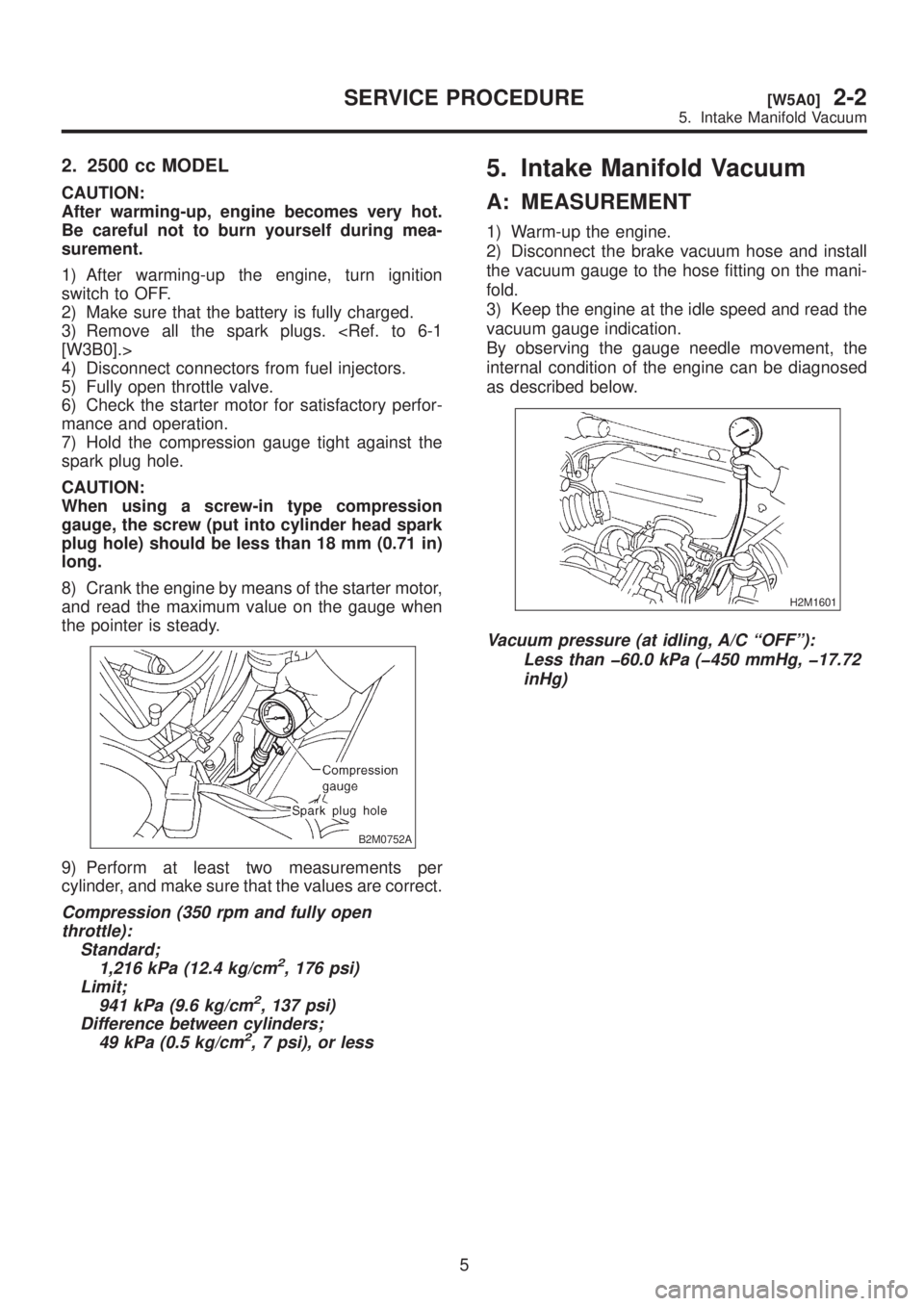
3) Keep the engine at the idle speed and read the
vacuum gauge indication.
By observing the gauge needle movement, the
internal condition of the engine can be diagnosed
as described below.
H2M1601
Vacuum pressure (at idling, A/C ªOFFº):
Less than þ60.0 kPa (þ450 mmHg, þ17.72
inHg)
5
[W5A0]2-2SERVICE PROCEDURE
5. Intake Manifold Vacuum
Page 39 of 1456
2. 2500 cc MODEL
CAUTION:
After warming-up, engine becomes very hot.
Be careful not to burn yourself during mea-
surement.
1) After warming-up the engine, turn ignition
switch to OFF.
2) Make sure that the battery is fully charged.
3) Remove all the spark plugs.
4) Disconnect connectors from fuel injectors.
5) Fully open throttle valve.
6) Check the starter motor for satisfactory perfor-
mance and operation.
7) Hold the compression gauge tight against the
spark plug hole.
CAUTION:
When using a screw-in type compression
gauge, the screw (put into cylinder head spark
plug hole) should be less than 18 mm (0.71 in)
long.
8) Crank the engine by means of the starter motor,
and read the maximum value on the gauge when
the pointer is steady.
B2M0752A
9) Perform at least two measurements per
cylinder, and make sure that the values are correct.
Compression (350 rpm and fully open
throttle):
Standard;
1,216 kPa (12.4 kg/cm
2, 176 psi)
Limit;
941 kPa (9.6 kg/cm
2, 137 psi)
Difference between cylinders;
49 kPa (0.5 kg/cm
2, 7 psi), or less
5. Intake Manifold Vacuum
A: MEASUREMENT
1) Warm-up the engine.
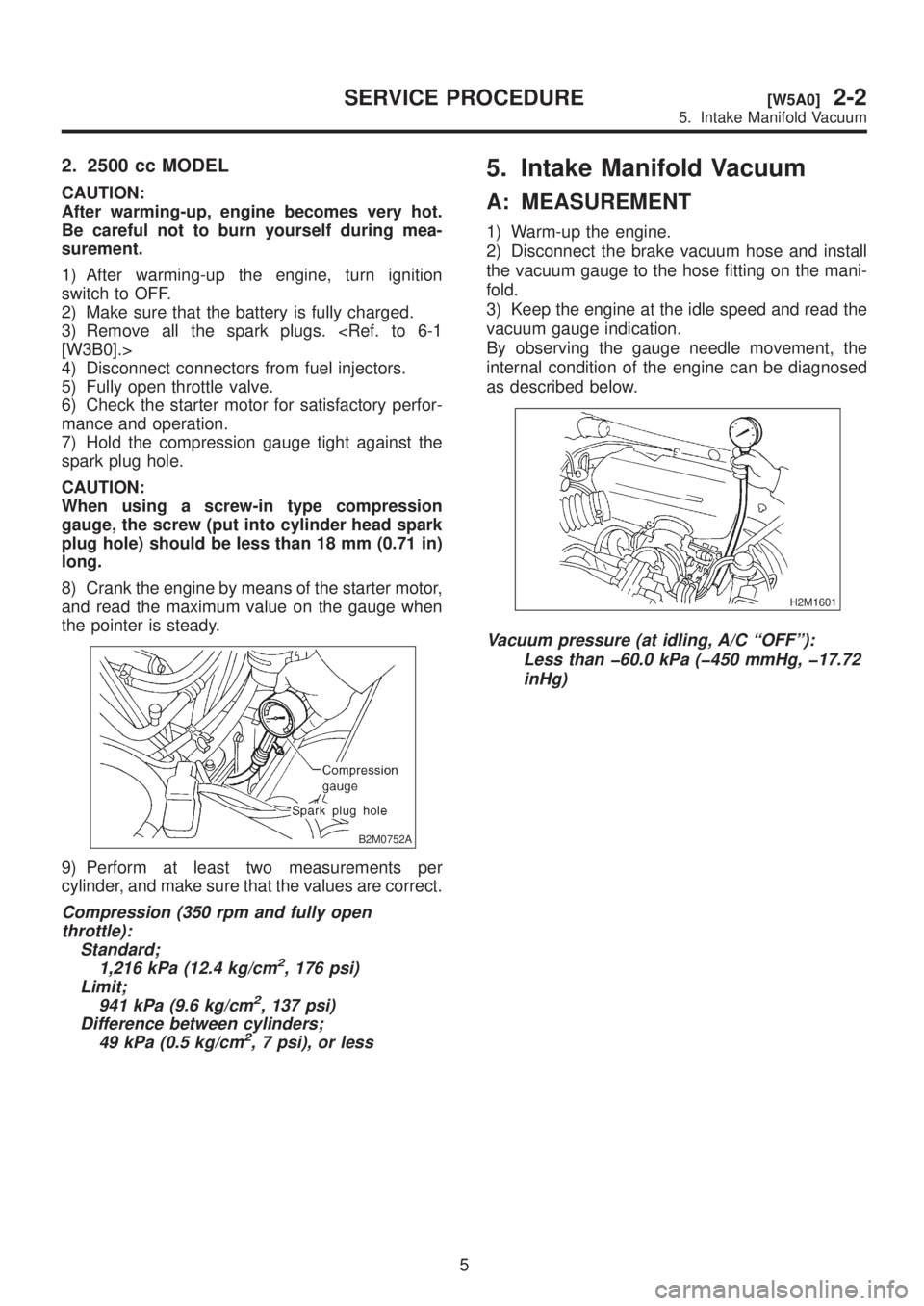
2) Disconnect the brake vacuum hose and install
the vacuum gauge to the hose fitting on the mani-
fold.
3) Keep the engine at the idle speed and read the
vacuum gauge indication.
By observing the gauge needle movement, the
internal condition of the engine can be diagnosed
as described below.
H2M1601
Vacuum pressure (at idling, A/C ªOFFº):
Less than þ60.0 kPa (þ450 mmHg, þ17.72
inHg)
5
[W5A0]2-2SERVICE PROCEDURE
5. Intake Manifold Vacuum
Page 132 of 1456

2. Engine Noise
Type of sound Condition Possible cause
Regular clicking soundSound increases as engine
speed increases.IValve mechanism is defective.
IIncorrect valve clearance
IWorn valve rocker
IWorn camshaft
IBroken valve spring
Heavy and dull clankOil pressure is low.IWorn crankshaft main bearing
IWorn connecting rod bearing (big end)
Oil pressure is normal.ILoose flywheel mounting bolts
IDamaged engine mounting
High-pitched clank
(Spark knock)Sound is noticeable when
accelerating with an overload.IIgnition timing advanced
IAccumulation of carbon inside combustion chamber
IWrong spark plug
IImproper gasoline
Clank when engine speed is
medium (1,000 to 2,000 rpm)Sound is reduced when fuel
injector connector of noisy cyl-
inder is disconnected.
(NOTE*)IWorn crankshaft main bearing
IWorn bearing at crankshaft end of connecting rod
Knocking sound when engine
is operating under idling speed
and engine is warmSound is reduced when fuel
injector connector of noisy cyl-
inder is disconnected.
(NOTE*)IWorn cylinder liner and piston ring
IBroken or stuck piston ring
IWorn piston pin and hole at piston end of connecting rod
Sound is not reduced if each
fuel injector connector is dis-
connected in turn. (NOTE*)IUnusually worn valve lifter
IWorn cam gear
IWorn camshaft journal bore in crankcase
Squeaky sound ÐIInsufficient generator lubrication
Rubbing sound ÐIDefective generator brush and rotor contact
Gear scream when starting
engineÐIDefective ignition starter switch
IWorn gear and starter pinion
Sound like polishing glass with
a dry clothÐILoose drive belt
IDefective engine coolant pump shaft
Hissing sound ÐILoss of compression
IAir leakage in air intake system, hoses, connections or
manifolds
Timing belt noise ÐILoose timing belt
IBelt contacting case/adjacent part
Valve tappet noise ÐIIncorrect valve clearance
NOTE*:
When disconnecting fuel injector connector, Malfunction Indicator Light (CHECK ENGINE light) illuminates and trouble code is
stored in ECM memory.
Therefore, carry out the CLEAR MEMORY MODE
necting fuel injector connector.
78
2-3a[K200]DIAGNOSTICS
2. Engine Noise