Page 824 of 1456

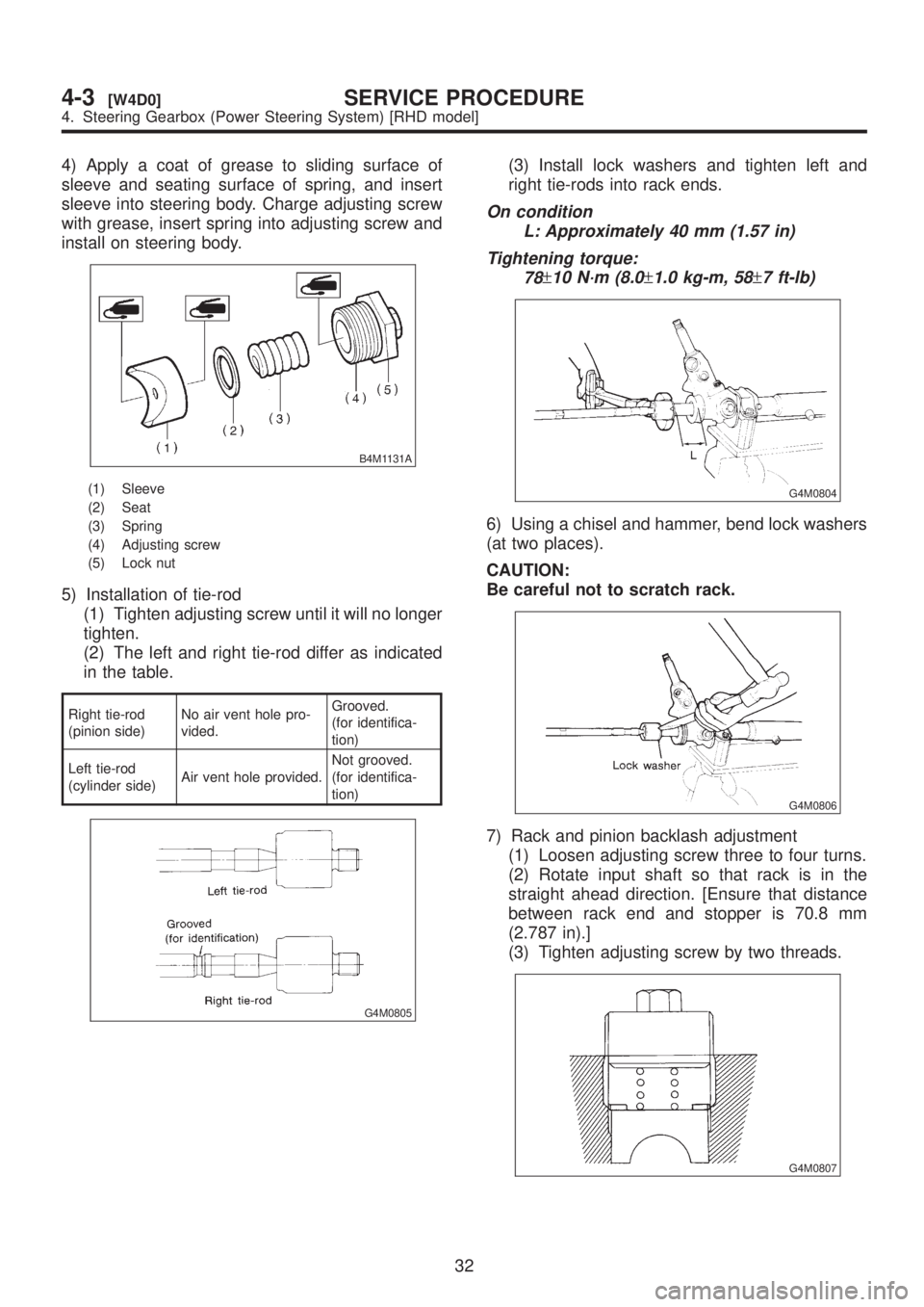
4) Apply a coat of grease to sliding surface of
sleeve and seating surface of spring, and insert
sleeve into steering body. Charge adjusting screw
with grease, insert spring into adjusting screw and
install on steering body.
B4M1131A
(1) Sleeve
(2) Seat
(3) Spring
(4) Adjusting screw
(5) Lock nut
5) Installation of tie-rod
(1) Tighten adjusting screw until it will no longer
tighten.
(2) The left and right tie-rod differ as indicated
in the table.
Right tie-rod
(pinion side)No air vent hole pro-
vided.Grooved.
(for identifica-
tion)
Left tie-rod
(cylinder side)Air vent hole provided.Not grooved.
(for identifica-
tion)
G4M0805
(3) Install lock washers and tighten left and
right tie-rods into rack ends.
On condition
L: Approximately 40 mm (1.57 in)
Tightening torque:
78
±10 N´m (8.0±1.0 kg-m, 58±7 ft-lb)
G4M0804
6) Using a chisel and hammer, bend lock washers
(at two places).
CAUTION:
Be careful not to scratch rack.
G4M0806
7) Rack and pinion backlash adjustment
(1) Loosen adjusting screw three to four turns.
(2) Rotate input shaft so that rack is in the
straight ahead direction. [Ensure that distance
between rack end and stopper is 70.8 mm
(2.787 in).]
(3) Tighten adjusting screw by two threads.
G4M0807
32
4-3[W4D0]SERVICE PROCEDURE
4. Steering Gearbox (Power Steering System) [RHD model]
Page 1063 of 1456

4. TRUNK LID OPENER
1) Remove rear seats, center pillar lower cover,
floor mat, rear arch cover and side sill cover (on the
driver's side).
2) Remove all clips which hold cable.
3) Disconnect cable from pull handle assembly.
4) Remove bolts and detach pull handle assembly.
5) Loosen bolts which hold lock assembly, and
remove it.
6) Remove striker from trunk lid.
G5M0147
7) Disconnect cable from striker.
NOTE:
IBe careful not to bend or break cable.
IBasic model vehicles do not have trunk lid
opener system.
8) Installation is in the reverse order of removal.
CAUTION:
IWhen installing cover to pull handle
assembly, observe the following:
IBe careful not to catch harness.
IEngage pull handle assembly pawls
firmly.
NOTE:
After installing opener cable, ensure it moves
smoothly.
B: ADJUSTMENT
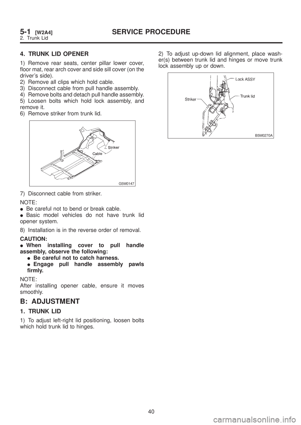
1. TRUNK LID
1) To adjust left-right lid positioning, loosen bolts
which hold trunk lid to hinges.2) To adjust up-down lid alignment, place wash-
er(s) between trunk lid and hinges or move trunk
lock assembly up or down.
B5M0270A
40
5-1[W2A4]SERVICE PROCEDURE
2. Trunk Lid
Page 1231 of 1456

4. Headlight
A: ADJUSTMENT
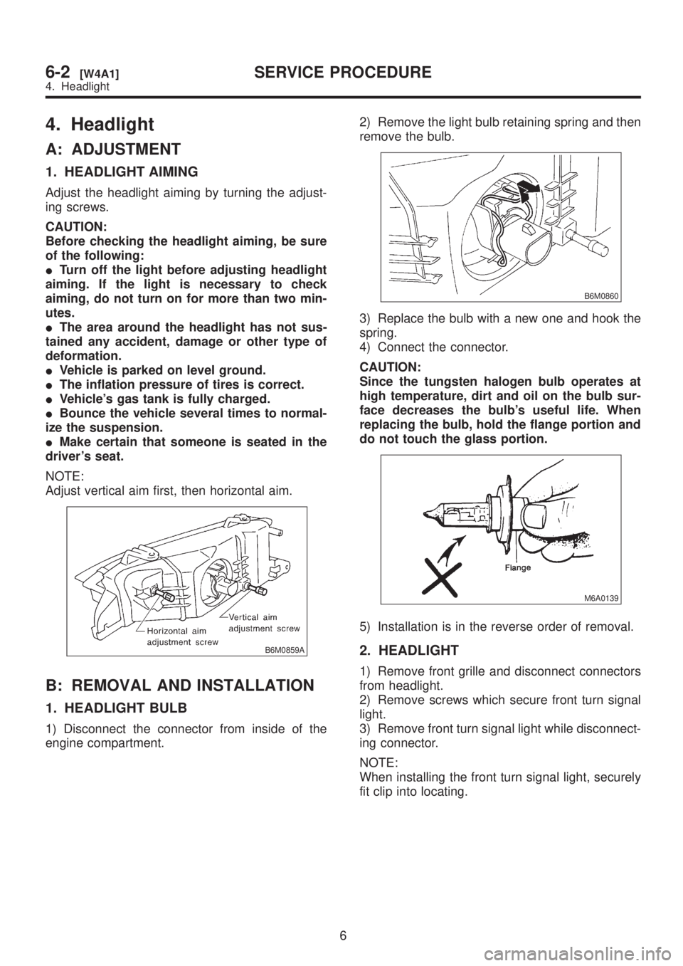
1. HEADLIGHT AIMING
Adjust the headlight aiming by turning the adjust-
ing screws.
CAUTION:
Before checking the headlight aiming, be sure
of the following:
ITurn off the light before adjusting headlight
aiming. If the light is necessary to check
aiming, do not turn on for more than two min-
utes.
IThe area around the headlight has not sus-
tained any accident, damage or other type of
deformation.
IVehicle is parked on level ground.
IThe inflation pressure of tires is correct.
IVehicle's gas tank is fully charged.
IBounce the vehicle several times to normal-
ize the suspension.
IMake certain that someone is seated in the
driver's seat.
NOTE:
Adjust vertical aim first, then horizontal aim.
B6M0859A
B: REMOVAL AND INSTALLATION
1. HEADLIGHT BULB
1) Disconnect the connector from inside of the
engine compartment.2) Remove the light bulb retaining spring and then
remove the bulb.
B6M0860
3) Replace the bulb with a new one and hook the
spring.
4) Connect the connector.
CAUTION:
Since the tungsten halogen bulb operates at
high temperature, dirt and oil on the bulb sur-
face decreases the bulb's useful life. When
replacing the bulb, hold the flange portion and
do not touch the glass portion.
M6A0139
5) Installation is in the reverse order of removal.
2. HEADLIGHT
1) Remove front grille and disconnect connectors
from headlight.
2) Remove screws which secure front turn signal
light.
3) Remove front turn signal light while disconnect-
ing connector.
NOTE:
When installing the front turn signal light, securely
fit clip into locating.
6
6-2[W4A1]SERVICE PROCEDURE
4. Headlight