Page 237 of 1456
C: CHECKING OF COOLING
SYSTEM
1) Remove radiator cap, top off radiator, and
attach tester to radiator in place of cap.
B2M0136
2) Apply a pressure of 157 kPa (1.6 kg/cm2,23
psi) to radiator to check if:
(1) Engine coolant leaks at/around radiator.
(2) Engine coolant leaks at/around hoses or
connections.
CAUTION:
IEngine should be off.
IWipe engine coolant from check points in
advance.
IBe careful to prevent engine coolant from
spurting out when removing tester.
IBe careful also not to deform filler neck of
radiator when installing or removing tester.
2. Water Pump
A: REMOVAL AND INSTALLATION
1. 2200 cc MODEL
1) Disconnect ground cable from battery.
B2M1723
2) Lift-up the vehicle.
3) Remove under cover.
B2M0014
4) Drain engine coolant completely.
[W1A0].>
B2M0015A
8
2-5[W1C0]SERVICE PROCEDURE
2. Water Pump
Page 249 of 1456
5. Radiator Cap
A: INSPECTION
1) Attach radiator cap to tester.
G2M0223
2) Increase pressure until tester gauge pointer
stops. Radiator cap is functioning properly if it
holds the service limit pressure for five to six sec-
onds.
Standard pressure:
78 Ð 98 kPa (0.8 Ð 1.0 kg/cm2,11Ð14
psi)
Service limit pressure:
69 kPa (0.7 kg/cm
2, 10 psi)
CAUTION:
Be sure to remove foreign matter and rust from
the cap in advance; otherwise, results of pres-
sure test will be incorrect.
6. Radiator Main Fan and Fan
Motor
A: REMOVAL AND INSTALLATION
1) Disconnect battery ground cable.
B2M1723
2) Lift-up the vehicle.
3) Remove under cover.
B2M0014
4) Disconnect connector of main fan motor.
B2M2043
18
2-5[W5A0]SERVICE PROCEDURE
5. Radiator Cap
Page 250 of 1456
5. Radiator Cap
A: INSPECTION
1) Attach radiator cap to tester.
G2M0223
2) Increase pressure until tester gauge pointer
stops. Radiator cap is functioning properly if it
holds the service limit pressure for five to six sec-
onds.
Standard pressure:
78 Ð 98 kPa (0.8 Ð 1.0 kg/cm2,11Ð14
psi)
Service limit pressure:
69 kPa (0.7 kg/cm
2, 10 psi)
CAUTION:
Be sure to remove foreign matter and rust from
the cap in advance; otherwise, results of pres-
sure test will be incorrect.
6. Radiator Main Fan and Fan
Motor
A: REMOVAL AND INSTALLATION
1) Disconnect battery ground cable.
B2M1723
2) Lift-up the vehicle.
3) Remove under cover.
B2M0014
4) Disconnect connector of main fan motor.
B2M2043
18
2-5[W5A0]SERVICE PROCEDURE
5. Radiator Cap
Page 452 of 1456
(5) Connect radiator inlet hose.
S2M0031
(6) Connect radiator outlet hose.
(7) Connect ATF cooler hoses. (AT vehicles)
B2M0016A
(8) Install reservoir tank.
(9) Install V-belt cover.
B2M2307
18) Install under cover.
B2M0014
19) Install battery in the vehicle, and connect
cables.
20) Fill coolant.
Engine coolant capacity;
5.8
(6.1 US qt, 5.1 lmp qt)
21) Charge A/C system with refrigerant.
22) Remove front hood stay, and close front hood.
23) Take off the vehicle from lift arms.
20
2-11[W1C0]SERVICE PROCEDURE
1. Engine
Page 528 of 1456

Automatic
transmis-
sionTransmis-
sionSelector positionP (Park)Transmission in
neutral, output mem-
ber immovable, and
engine start possible
R (Reverse)Transmission in
reverse for backing
N (Neutral)Transmission in
neutral, and engine
start possible
D (Drive)Automatic gear
change
1st
¬
®2nd¬
®3rd¬
®4th
3 (3rd)Automatic gear
change
1st
¬
®2nd¬
®3rd
¬4th
2 (2nd)2nd gear locked
(Deceleration pos-
sible 4th®3rd®
2nd)
1 (1st)1st gear locked
(Deceleration pos-
sible 4th®3rd®
2nd®1st)
Control method Hydraulic remote control
Oil pumpType Trochoid constant-displacement pump
Driving method Driven by engine
Number of teethInner rotor 9
Outer rotor 10
Hydraulic
controlTypeElectronic/hydraulic control [Four forward speed changes by electri-
cal signals of vehicle speed and accelerator (throttle) opening]
Fluid Dexron II or Dexron III type Automatic transmission fluid
Fluid capacity2200 cc 8.4 Ð 8.7(8.9 Ð 9.2 US qt, 7.4 Ð 7.7 Imp qt)
2500 cc 9.3 Ð 9.6(9.8 Ð 10.1 US qt, 8.2 Ð 8.4 Imp qt)
Lubrica-
tionLubrication system Forced feed lubrication with oil pump
Oil Automatic transmission fluid (above mentioned.)
Cooling Cooling system Liquid-cooled cooler incorporated in radiator
HarnessInhibitor switch 12 poles
Transmission harness 17 poles
TransferTransfer clutch Hydraulic multi-plate clutch
Plate number of transfer clutchDrive plate & driven
plate2200 cc 4
2500 cc 5
Control method Electronic, hydraulic type
LubricantThe same Automatic Transmission
Fluid used in automatic transmission.
1st reduction gear ratio 1.000 (53/53)
3
[S1A0]3-2SPECIFICATIONS AND SERVICE DATA
1. Automatic Transmission and Differential
Page 976 of 1456

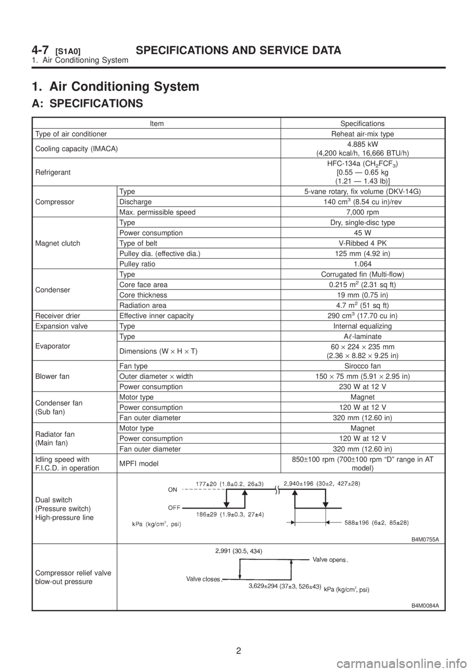
1. Air Conditioning System
A: SPECIFICATIONS
Item Specifications
Type of air conditioner Reheat air-mix type
Cooling capacity (IMACA)4.885 kW
(4,200 kcal/h, 16,666 BTU/h)
RefrigerantHFC-134a (CH
2FCF3)
[0.55 Ð 0.65 kg
(1.21 Ð 1.43 lb)]
CompressorType 5-vane rotary, fix volume (DKV-14G)
Discharge 140 cm
3(8.54 cu in)/rev
Max. permissible speed 7,000 rpm
Magnet clutchType Dry, single-disc type
Power consumption 45 W
Type of belt V-Ribbed 4 PK
Pulley dia. (effective dia.) 125 mm (4.92 in)
Pulley ratio 1.064
CondenserType Corrugated fin (Multi-flow)
Core face area 0.215 m
2(2.31 sq ft)
Core thickness 19 mm (0.75 in)
Radiation area 4.7 m
2(51 sq ft)
Receiver drier Effective inner capacity 290 cm3(17.70 cu in)
Expansion valve Type Internal equalizing
EvaporatorType A-laminate
Dimensions (W´H´T)60´224´235 mm
(2.36´8.82´9.25 in)
Blower fanFan type Sirocco fan
Outer diameter´width 150´75 mm (5.91´2.95 in)
Power consumption 230 W at 12 V
Condenser fan
(Sub fan)Motor type Magnet
Power consumption 120 W at 12 V
Fan outer diameter 320 mm (12.60 in)
Radiator fan
(Main fan)Motor type Magnet
Power consumption 120 W at 12 V
Fan outer diameter 320 mm (12.60 in)
Idling speed with
F.I.C.D. in operationMPFI model850±100 rpm (700±100 rpm ªDº range in AT
model)
Dual switch
(Pressure switch)
High-pressure line
B4M0755A
Compressor relief valve
blow-out pressure
B4M0084A
2
4-7[S1A0]SPECIFICATIONS AND SERVICE DATA
1. Air Conditioning System