Page 289 of 1456
16) Disconnect spark plug cords from ignition coil
and ignitor assembly.
B2M2312
17) Disconnect PCV hose assembly from intake
manifold.
B2M2313
18) Disconnect engine coolant hoses from throttle
body.
B2M2299
19) Disconnect brake booster hose.
B2M2314
20) Remove air cleaner case stay RH and engine
harness bracket, and disconnect engine harness
connectors from bulkhead harness connectors.21) Pull out engine harness connector from
bracket.
B2M2315
22) Disconnect connectors from engine coolant
temperature sensor (A) and thermometer (B).
B2M0345B
23) Disconnect knock sensor connector.
B2M2327A
24) Disconnect connector from camshaft position
sensor.
B2M2317B
28
2-7[W4A1]SERVICE PROCEDURE
4. Intake Manifold
Page 293 of 1456
18) Disconnect PCV hose (A) and pressure regu-
lator vacuum hose (B) from intake manifold.
19) Disconnect vacuum hose (C) to cruise control
diaphragm. (With cruise control models)
S2M0089A
20) Disconnect engine coolant hose from throttle
body.
B2M2304
21) Disconnect brake booster hose.
B2M2314
22) Remove air intake chamber stay RH, engine
harness bracket from transmission housing, and
disconnect engine harness connectors from bulk-
head harness connectors.
B2M2315
23) Disconnect connectors from engine coolant
temperature sensor (A) and thermometer (B).
B2M0345B
24) Disconnect knock sensor connector.
B2M2327A
25) Disconnect connector from camshaft position
sensor.
B2M2317B
32
2-7[W4A2]SERVICE PROCEDURE
4. Intake Manifold
Page 297 of 1456
20) Remove EGR pipe.
S2M0078
21) Remove engine harness bracket from trans-
mission housing, and disconnect engine harness
connectors from bulkhead harness connectors.
S2M0082A
22) Disconnect connectors from engine coolant
temperature sensor (A) and thermometer (B).
B2M0345B
23) Disconnect knock sensor connector.
B2M1243A
24) Disconnect connector from camshaft position
sensor.
S2M0183
25) Disconnect connector from crankshaft position
sensor.
B2M1252A
26) Disconnect connector from oil pressure switch
B2M1253A
27) Disconnect fuel hoses from fuel pipes.
WARNING:
Catch fuel from hoses in a container.
S2M0090A
36
2-7[W4A3]SERVICE PROCEDURE
4. Intake Manifold
Page 321 of 1456
5. Engine Coolant Temperature
Sensor
A: REMOVAL AND INSTALLATION
1. 2200 cc CALIFORNIA SPEC. VEHICLES
1) Disconnect battery ground cable.
B2M1723
2) Remove bolt which installs air intake duct (A)
on the front side of body.
B2M2283A
3) Remove bolt which installs air intake duct (B)
on body.
B2M2284A
4) Remove air intake duct (A) and (B) as a unit.
B2M2012
5) Disconnect connector from engine coolant tem-
perature sensor.
G2M0407
6) Remove engine coolant temperature sensor.
7) Installation is in the reverse order of removal.
Tightening torque:
25
±3 N´m (2.5±0.3 kg-m, 18.1±2.2 ft-lb)
S2M0513
60
2-7[W5A1]SERVICE PROCEDURE
5. Engine Coolant Temperature Sensor
Page 322 of 1456
2. EXCEPT 2200 cc CALIFORNIA SPEC.
VEHICLES
1) Disconnect battery ground cable.
B2M1723
2) Disconnect connector from mass air flow sen-
sor.
B2M2018
3) Loosen clamp which connects air intake duct to
air intake chamber.
B2M2019
4) Remove two clips of air cleaner upper cover.
B2M2289
5) Remove air intake duct and air cleaner upper
cover as a unit.
B2M2020
6) Disconnect connector from engine coolant tem-
perature sensor.
G2M0407
7) Remove bolts which install idle air control sole-
noid valve, and move it aside. (2500 cc model only)
NOTE:
At this time, do not disconnect engine coolant
hoses from idle air control solenoid valve.
B2M0166
61
[W5A2]2-7SERVICE PROCEDURE
5. Engine Coolant Temperature Sensor
Page 323 of 1456
8) Remove engine coolant temperature sensor.
9) Installation is in the reverse order of removal.
Tightening torque:
25
±3 N´m (2.5±0.3 kg-m, 18.1±2.2 ft-lb)
S2M0095
6. Crankshaft Position Sensor
A: REMOVAL AND INSTALLATION
1) Remove bolt which install crankshaft position
sensor to cylinder block.
G2M0408
2) Remove crankshaft position sensor, and dis-
connect connector from it.
G2M0409
3) Installation is in the reverse order of removal.
Tightening torque:
6.4
±0.5 N´m (0.65±0.05 kg-m, 4.7±0.4 ft-lb)
G2M0408
62
2-7[W6A0]SERVICE PROCEDURE
6. Crankshaft Position Sensor
Page 324 of 1456
8) Remove engine coolant temperature sensor.
9) Installation is in the reverse order of removal.
Tightening torque:
25
±3 N´m (2.5±0.3 kg-m, 18.1±2.2 ft-lb)
S2M0095
6. Crankshaft Position Sensor
A: REMOVAL AND INSTALLATION
1) Remove bolt which install crankshaft position
sensor to cylinder block.
G2M0408
2) Remove crankshaft position sensor, and dis-
connect connector from it.
G2M0409
3) Installation is in the reverse order of removal.
Tightening torque:
6.4
±0.5 N´m (0.65±0.05 kg-m, 4.7±0.4 ft-lb)
G2M0408
62
2-7[W6A0]SERVICE PROCEDURE
6. Crankshaft Position Sensor
Page 568 of 1456

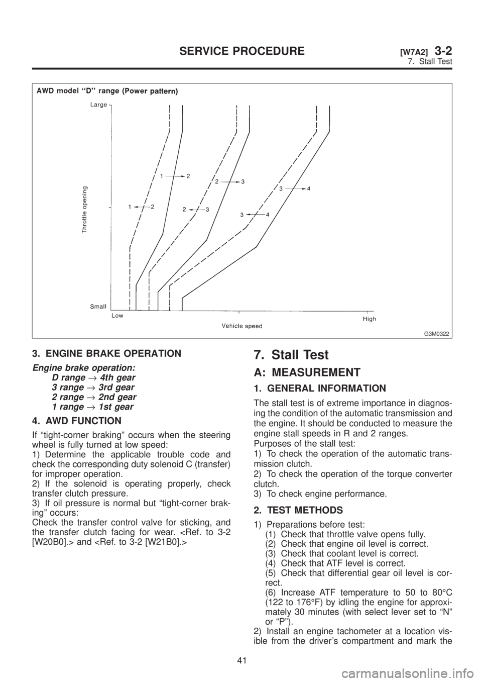
G3M0322
3. ENGINE BRAKE OPERATION
Engine brake operation:
D range
®4th gear
3 range
®3rd gear
2 range
®2nd gear
1 range
®1st gear
4. AWD FUNCTION
If ªtight-corner brakingº occurs when the steering
wheel is fully turned at low speed:
1) Determine the applicable trouble code and
check the corresponding duty solenoid C (transfer)
for improper operation.
2) If the solenoid is operating properly, check
transfer clutch pressure.
3) If oil pressure is normal but ªtight-corner brak-
ingº occurs:
Check the transfer control valve for sticking, and
the transfer clutch facing for wear.
[W20B0].> and
7. Stall Test
A: MEASUREMENT
1. GENERAL INFORMATION
The stall test is of extreme importance in diagnos-
ing the condition of the automatic transmission and
the engine. It should be conducted to measure the
engine stall speeds in R and 2 ranges.
Purposes of the stall test:
1) To check the operation of the automatic trans-
mission clutch.
2) To check the operation of the torque converter
clutch.
3) To check engine performance.
2. TEST METHODS
1) Preparations before test:
(1) Check that throttle valve opens fully.
(2) Check that engine oil level is correct.
(3) Check that coolant level is correct.
(4) Check that ATF level is correct.
(5) Check that differential gear oil level is cor-
rect.
(6) Increase ATF temperature to 50 to 80ÉC
(122 to 176ÉF) by idling the engine for approxi-
mately 30 minutes (with select lever set to ªNº
or ªPº).
2) Install an engine tachometer at a location vis-
ible from the driver's compartment and mark the
41
[W7A2]3-2SERVICE PROCEDURE
7. Stall Test