Page 869 of 1456
![SUBARU LEGACY 1999 Service Repair Manual Trouble Possible cause Corrective action
Rattling noise (intermittent)
While engine is running.Interference with adjacent parts Check clearance.
Correct if necessary.
<Ref. to 4-3 [K1F0].>
Loosened in SUBARU LEGACY 1999 Service Repair Manual Trouble Possible cause Corrective action
Rattling noise (intermittent)
While engine is running.Interference with adjacent parts Check clearance.
Correct if necessary.
<Ref. to 4-3 [K1F0].>
Loosened in](/manual-img/17/57435/w960_57435-868.png)
Trouble Possible cause Corrective action
Rattling noise (intermittent)
While engine is running.Interference with adjacent parts Check clearance.
Correct if necessary.
Loosened installation of oil pump, oil tank, pump bracket, gear-
box or crossmemberRetighten.
Loosened installation of oil pump pulley or other pulley(s) Retighten.
Loosened linkage or play of steering or suspension
Loosened tightening of joint or steering columnRetighten or replace.
Sound generates from the inside of gearbox or oil pump. Replace the gearbox or oil
pump.
Knocking
When turning steering wheel
in both direction with small
angle repeatedly at engine
ON or OFF.Excessive backlash
Loosened lock nut for adjusting backlashAdjust and retighten.
Loosened tightening or play of tie-rod, tie-rod end Retighten or replace.
Grinding noise (continuous)
While engine is running.Vane pump aeration Inspect and retighten fluid line
connection.
Refill fluid and vent air.
Vane pump seizing Replace oil pump.
Pulley bearing seizing of oil pump Replace oil pump.
Folded hose, flat pipe Replace.
Squeal, squeak (intermittent
or continuous)
While engine is running.Maladjustment of pulley belt
Damaged or charged pulley belt
Unequal length of pulley beltsAdjust or replace.
(Replace two belts as a set.)
Run out or soilage of V-groove surface of oil pump pulley Clean or replace.
Sizzling noise (continuous)
While engine is running.Fluid aeration Fix wrong part causing aera-
tion.
Replace fluid and vent air.
Damaged pipe of gearbox Replace pipe.
Abnormal inside of hose or pipe
Flat hose or pipeRectify or replace.
Abnormal inside of oil tank Replace.
Removed oil tank cap Install cap.
Whistle (continuous)
While engine is running.Abnormal pipe of gearbox or abnormal inside of hose Replace bad parts of gearbox
or hose.
Whine or growl (continuous or
intermittent)
While engine is running with/
without steering turned.Loosened installation of oil pump, oil pump bracket Retighten.
Abnormal inside of oil pump, hose Replace oil pump, hose, if the
noise can be heard when run-
ning as well as stand still.
Torque converter growl air conditioner compression growl Remove power steering pul-
ley belt and confirm.
Creaking noise (intermittent)
While engine is running with
steering turned.Abnormal inside of gearbox Replace bad parts of gear-
box.
Abnormal bearing for steering shaft Apply grease or replace.
Generates when turning steering wheel with brake (service or
parking) applied.If the noise goes off when
brake is released, it is normal.
Vibration
While engine is running with/
without steering turned.Too low engine speed at start Adjust and instruct custom-
ers.
Vane pump aeration Fix wrong part.
Vent air.
Damaged valve in oil pump, gearbox Replace oil pump, bad parts
of gearbox.
Looseness of play of steering, suspension parts Retighten.
75
[K1E0]4-3DIAGNOSTICS
1. Power Steering
Page 933 of 1456

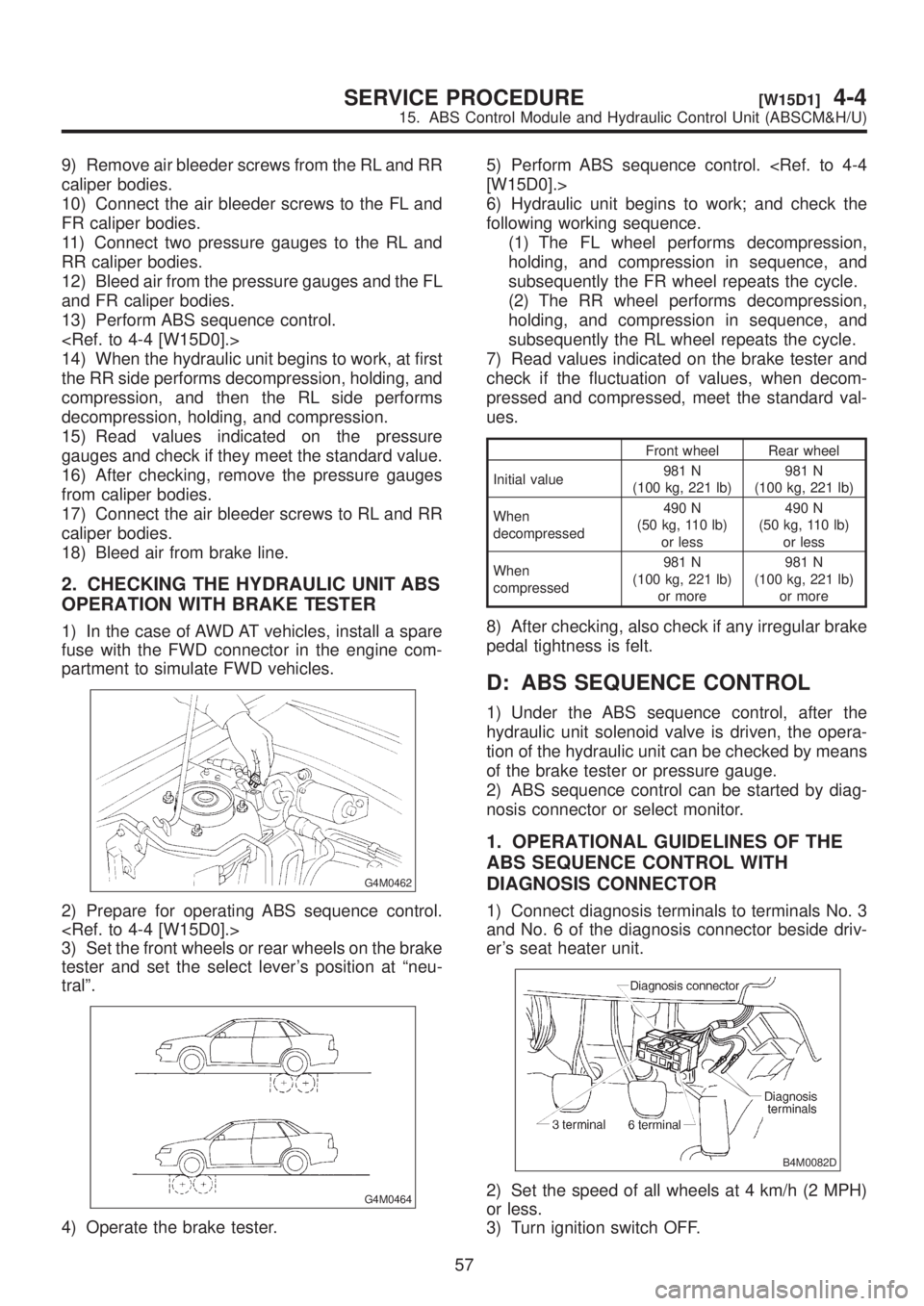
7) Disconnect brake pipes from ABSCM&H/U.
CAUTION:
Wrap brake pipes with vinyl bag to avoid spill-
ing brake fluid on vehicle body.
8) Remove ABSCM&H/U from engine compart-
ment.
CAUTION:
IABSCM&H/U cannot be disassembled. Do
not attempt to loosen bolts and nuts.
IDo not drop or bump ABSCM&H/U.
IDo not turn the ABSCM&H/U upside down or
place it on its side.
IBe careful to prevent foreign particles from
getting into ABSCM&H/U.
IApply a coat of rust-preventive wax (Nippeco
LT or GB) to bracket attaching bolt after tight-
ening.
IDo not pull harness disconnecting harness
connector.
B4M1222
B: INSPECTION
1) Check connected and fixed condition of con-
nector.
2) Check specifications of the mark with
ABSCM&H/U.
Mark Model
C5 AWD AT
C6 AWD MT
B4M1248A
C: CHECKING THE HYDRAULIC
UNIT ABS OPERATION
1. CHECKING THE HYDRAULIC UNIT ABS
OPERATION BY PRESSURE GAUGE
1) Lift-up vehicle and remove wheels.
2) Disconnect the air bleeder screws from the FL
and FR caliper bodies.
3) Connect two pressure gauges to the FL and FR
caliper bodies.
CAUTION:
IPressure gauges used exclusively for brake
fluid must be used.
IDo not employ pressure gauge previously
used for transmission since the piston seal is
expanded which may lead to malfunction of the
brake.
NOTE:
Wrap sealing tape around the pressure gauge.
B4M0633A
4) Bleed air from the pressure gauges.
5) Perform ABS sequence control.
6) When the hydraulic unit begins to work, and
first the FL side performs decompression, holding,
and compression, and then the FR side performs
decompression, holding, and compression.
7) Read values indicated on the pressure gauge
and check if the fluctuation of the values between
decompression and compression meets the stan-
dard values. Also check if any irregular brake pedal
tightness is felt.
Front wheel Rear wheel
Initial value3,432 kPa
(35 kg/cm
2, 498 psi)3,432 kPa
(35 kg/cm2, 498 psi)
When
decom-
pressed490 kPa
(5 kg/cm
2, 71 psi)
or less490 kPa
(5 kg/cm2, 71 psi)
or less
When
compressed3,432 kPa
(35 kg/cm
2, 498 psi)
or more3,432 kPa
(35 kg/cm2, 498 psi)
or more
8) Remove pressure gauges from FL and FR cali-
per bodies.
56
4-4[W15B0]SERVICE PROCEDURE
15. ABS Control Module and Hydraulic Control Unit (ABSCM&H/U)
Page 934 of 1456

9) Remove air bleeder screws from the RL and RR
caliper bodies.
10) Connect the air bleeder screws to the FL and
FR caliper bodies.
11) Connect two pressure gauges to the RL and
RR caliper bodies.
12) Bleed air from the pressure gauges and the FL
and FR caliper bodies.
13) Perform ABS sequence control.
14) When the hydraulic unit begins to work, at first
the RR side performs decompression, holding, and
compression, and then the RL side performs
decompression, holding, and compression.
15) Read values indicated on the pressure
gauges and check if they meet the standard value.
16) After checking, remove the pressure gauges
from caliper bodies.
17) Connect the air bleeder screws to RL and RR
caliper bodies.
18) Bleed air from brake line.
2. CHECKING THE HYDRAULIC UNIT ABS
OPERATION WITH BRAKE TESTER
1) In the case of AWD AT vehicles, install a spare
fuse with the FWD connector in the engine com-
partment to simulate FWD vehicles.
G4M0462
2) Prepare for operating ABS sequence control.
3) Set the front wheels or rear wheels on the brake
tester and set the select lever's position at ªneu-
tralº.
G4M0464
4) Operate the brake tester.5) Perform ABS sequence control.
[W15D0].>
6) Hydraulic unit begins to work; and check the
following working sequence.
(1) The FL wheel performs decompression,
holding, and compression in sequence, and
subsequently the FR wheel repeats the cycle.
(2) The RR wheel performs decompression,
holding, and compression in sequence, and
subsequently the RL wheel repeats the cycle.
7) Read values indicated on the brake tester and
check if the fluctuation of values, when decom-
pressed and compressed, meet the standard val-
ues.
Front wheel Rear wheel
Initial value981 N
(100 kg, 221 lb)981 N
(100 kg, 221 lb)
When
decompressed490 N
(50 kg, 110 lb)
or less490 N
(50 kg, 110 lb)
or less
When
compressed981 N
(100 kg, 221 lb)
or more981 N
(100 kg, 221 lb)
or more
8) After checking, also check if any irregular brake
pedal tightness is felt.
D: ABS SEQUENCE CONTROL
1) Under the ABS sequence control, after the
hydraulic unit solenoid valve is driven, the opera-
tion of the hydraulic unit can be checked by means
of the brake tester or pressure gauge.
2) ABS sequence control can be started by diag-
nosis connector or select monitor.
1. OPERATIONAL GUIDELINES OF THE
ABS SEQUENCE CONTROL WITH
DIAGNOSIS CONNECTOR
1) Connect diagnosis terminals to terminals No. 3
and No. 6 of the diagnosis connector beside driv-
er's seat heater unit.
B4M0082D
2) Set the speed of all wheels at 4 km/h (2 MPH)
or less.
3) Turn ignition switch OFF.
57
[W15D1]4-4SERVICE PROCEDURE
15. ABS Control Module and Hydraulic Control Unit (ABSCM&H/U)