Page 439 of 1456

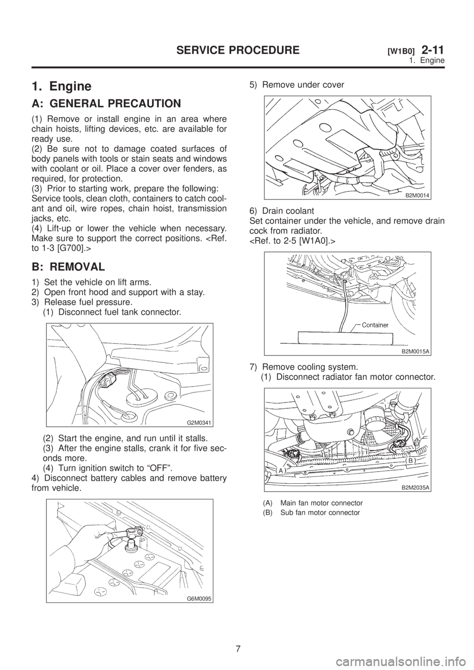
1. Engine
A: GENERAL PRECAUTION
(1) Remove or install engine in an area where
chain hoists, lifting devices, etc. are available for
ready use.
(2) Be sure not to damage coated surfaces of
body panels with tools or stain seats and windows
with coolant or oil. Place a cover over fenders, as
required, for protection.
(3) Prior to starting work, prepare the following:
Service tools, clean cloth, containers to catch cool-
ant and oil, wire ropes, chain hoist, transmission
jacks, etc.
(4) Lift-up or lower the vehicle when necessary.
Make sure to support the correct positions.
to 1-3 [G700].>
B: REMOVAL
1) Set the vehicle on lift arms.
2) Open front hood and support with a stay.
3) Release fuel pressure.
(1) Disconnect fuel tank connector.
G2M0341
(2) Start the engine, and run until it stalls.
(3) After the engine stalls, crank it for five sec-
onds more.
(4) Turn ignition switch to ªOFFº.
4) Disconnect battery cables and remove battery
from vehicle.
G6M0095
5) Remove under cover
B2M0014
6) Drain coolant
Set container under the vehicle, and remove drain
cock from radiator.
B2M0015A
7) Remove cooling system.
(1) Disconnect radiator fan motor connector.
B2M2035A
(A) Main fan motor connector
(B) Sub fan motor connector
7
[W1B0]2-11SERVICE PROCEDURE
1. Engine
Page 452 of 1456
(5) Connect radiator inlet hose.
S2M0031
(6) Connect radiator outlet hose.
(7) Connect ATF cooler hoses. (AT vehicles)
B2M0016A
(8) Install reservoir tank.
(9) Install V-belt cover.
B2M2307
18) Install under cover.
B2M0014
19) Install battery in the vehicle, and connect
cables.
20) Fill coolant.
Engine coolant capacity;
5.8
(6.1 US qt, 5.1 lmp qt)
21) Charge A/C system with refrigerant.
22) Remove front hood stay, and close front hood.
23) Take off the vehicle from lift arms.
20
2-11[W1C0]SERVICE PROCEDURE
1. Engine
Page 967 of 1456

1. Precaution
A: SUPPLEMENTAL RESTRAINT
SYSTEM ªAIRBAGº
CAUTION:
IAll Airbag system wiring harness and con-
nectors are colored yellow. Do not use electri-
cal test equipment on these circuit.
IBe careful not to damage Airbag system wir-
ing harness when servicing the instrument
panel, heater unit, blower motor and control
unit.
Airbag system wiring harness is routed near the
instrument panel, heater unit, blower motor and
control unit.
2. Heater Unit
A: REMOVAL AND INSTALLATION
1) Disconnect GND cable from battery.
2) Remove heater hoses (inlet, outlet) in engine
compartment.
NOTE:
Drain as much coolant from heater unit as
possible, and plug disconnected hose with cloth.
3) Remove instrument panel.
[W1A0].>
4) Remove steering support beam.
[C600].>
5) Remove evaporator. (With A/C model)
4-7 [W14A0].>
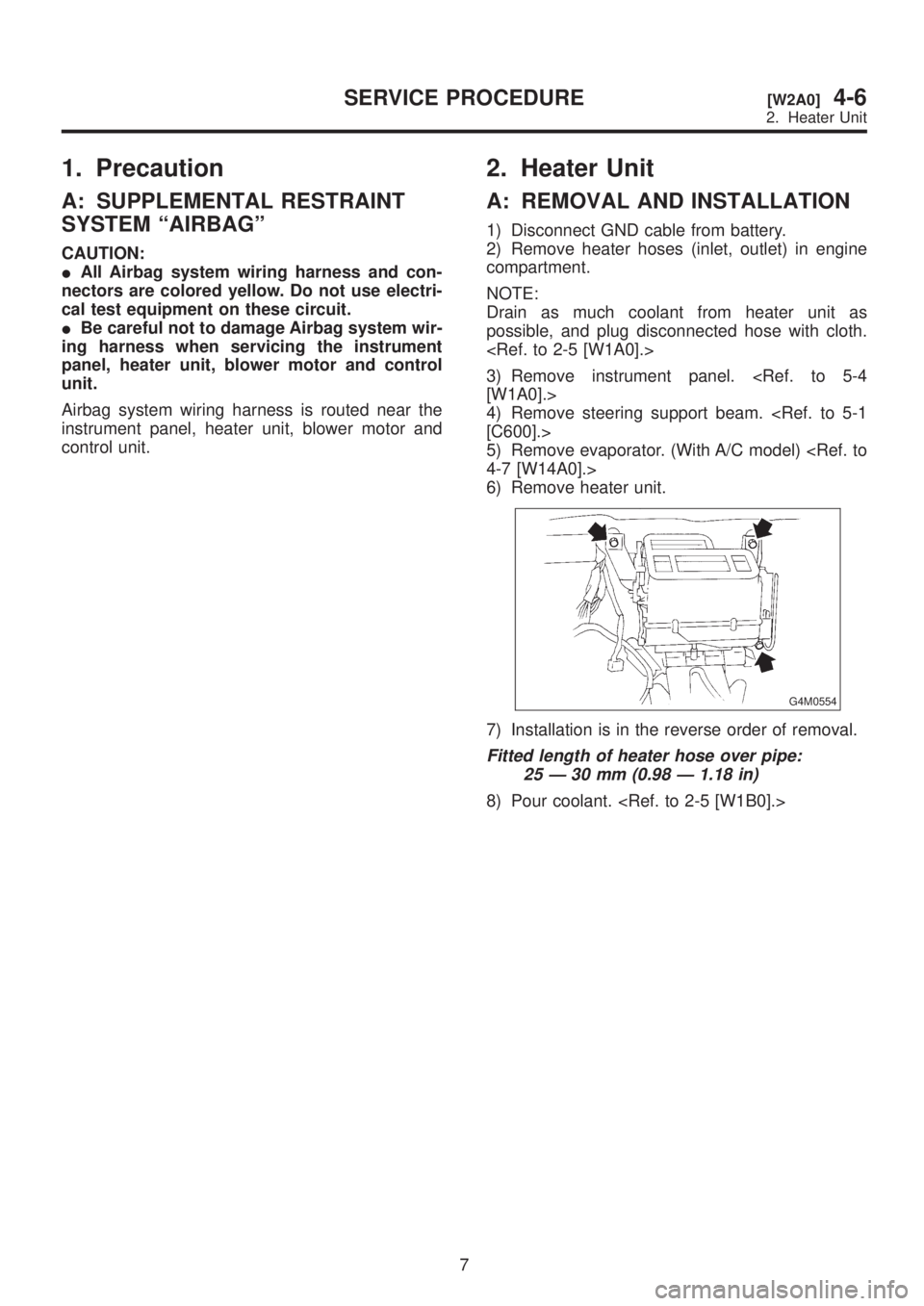
6) Remove heater unit.
G4M0554
7) Installation is in the reverse order of removal.
Fitted length of heater hose over pipe:
25 Ð 30 mm (0.98 Ð 1.18 in)
8) Pour coolant.
7
[W2A0]4-6SERVICE PROCEDURE
2. Heater Unit
Page 968 of 1456

1. Precaution
A: SUPPLEMENTAL RESTRAINT
SYSTEM ªAIRBAGº
CAUTION:
IAll Airbag system wiring harness and con-
nectors are colored yellow. Do not use electri-
cal test equipment on these circuit.
IBe careful not to damage Airbag system wir-
ing harness when servicing the instrument
panel, heater unit, blower motor and control
unit.
Airbag system wiring harness is routed near the
instrument panel, heater unit, blower motor and
control unit.
2. Heater Unit
A: REMOVAL AND INSTALLATION
1) Disconnect GND cable from battery.
2) Remove heater hoses (inlet, outlet) in engine
compartment.
NOTE:
Drain as much coolant from heater unit as
possible, and plug disconnected hose with cloth.
3) Remove instrument panel.
[W1A0].>
4) Remove steering support beam.
[C600].>
5) Remove evaporator. (With A/C model)
4-7 [W14A0].>
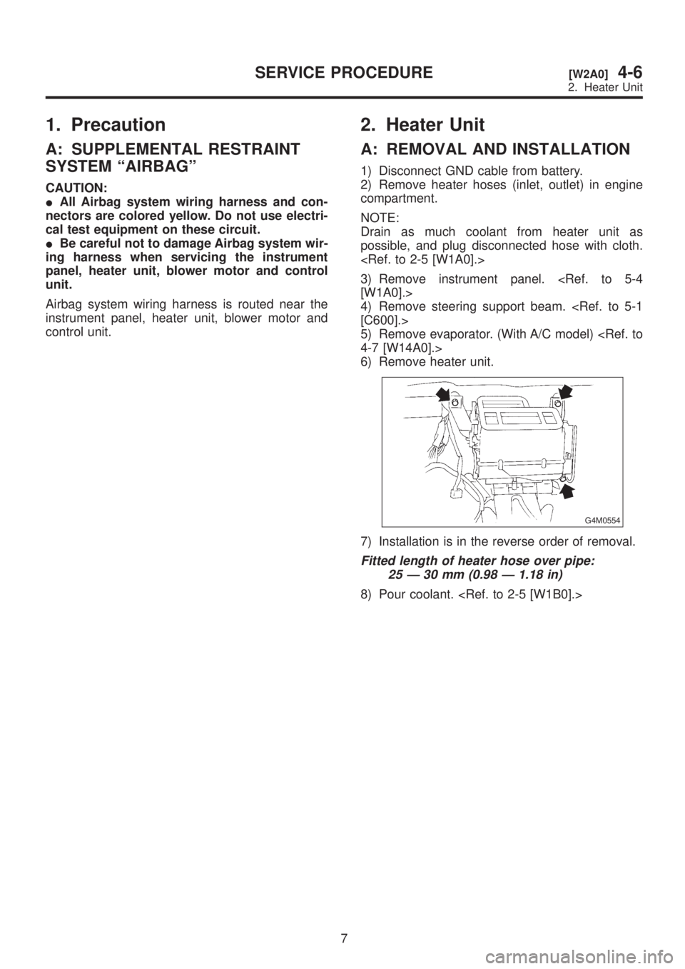
6) Remove heater unit.
G4M0554
7) Installation is in the reverse order of removal.
Fitted length of heater hose over pipe:
25 Ð 30 mm (0.98 Ð 1.18 in)
8) Pour coolant.
7
[W2A0]4-6SERVICE PROCEDURE
2. Heater Unit