1999 SUBARU FORESTER oil
[x] Cancel search: oilPage 193 of 345
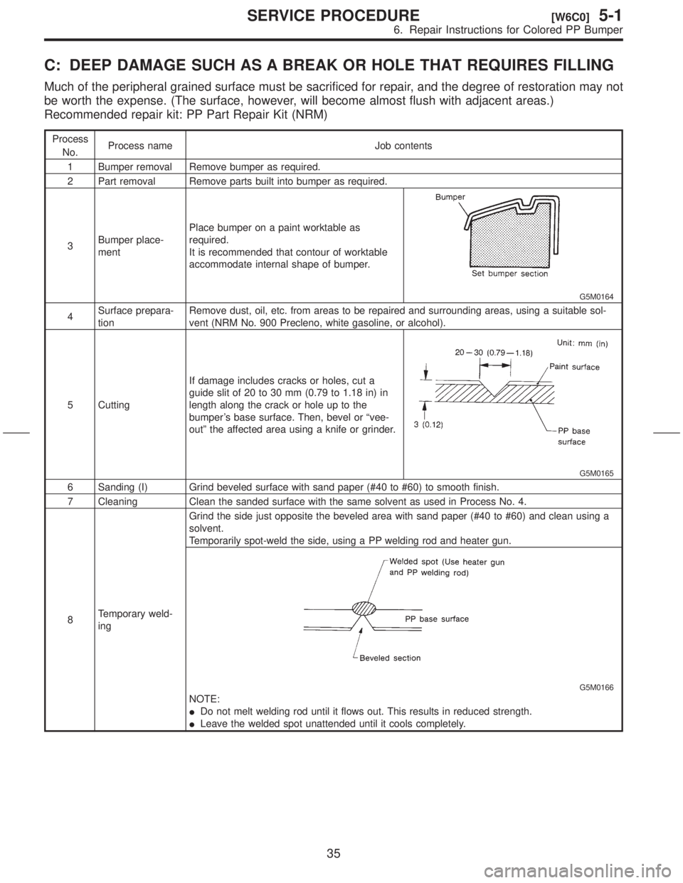
C: DEEP DAMAGE SUCH AS A BREAK OR HOLE THAT REQUIRES FILLING
Much of the peripheral grained surface must be sacrificed for repair, and the degree of restoration may not
be worth the expense. (The surface, however, will become almost flush with adjacent areas.)
Recommended repair kit: PP Part Repair Kit (NRM)
Process
No.Process name Job contents
1 Bumper removal Remove bumper as required.
2 Part removal Remove parts built into bumper as required.
3Bumper place-
mentPlace bumper on a paint worktable as
required.
It is recommended that contour of worktable
accommodate internal shape of bumper.
G5M0164
4Surface prepara-
tionRemove dust, oil, etc. from areas to be repaired and surrounding areas, using a suitable sol-
vent (NRM No. 900 Precleno, white gasoline, or alcohol).
5 CuttingIf damage includes cracks or holes, cut a
guide slit of 20 to 30 mm (0.79 to 1.18 in) in
length along the crack or hole up to the
bumper's base surface. Then, bevel or ªvee-
outº the affected area using a knife or grinder.
G5M0165
6 Sanding (I) Grind beveled surface with sand paper (#40 to #60) to smooth finish.
7 Cleaning Clean the sanded surface with the same solvent as used in Process No. 4.
8Temporary weld-
ingGrind the side just opposite the beveled area with sand paper (#40 to #60) and clean using a
solvent.
Temporarily spot-weld the side, using a PP welding rod and heater gun.
G5M0166
NOTE:
IDo not melt welding rod until it flows out. This results in reduced strength.
ILeave the welded spot unattended until it cools completely.
35
[W6C0]5-1SERVICE PROCEDURE
6. Repair Instructions for Colored PP Bumper
Page 234 of 345
3. Rear Gate
A: REMOVAL AND INSTALLATION
CAUTION:
IBe careful not to scratch coated surfaces of
vehicle body and window glass during
removal. Place a cloth over the affected area.
IBe careful not to damage trim panels.
IUse an assistant when handling heavy parts.
IBe careful not to damage or lose small parts.
1. REAR GATE ASSEMBLY
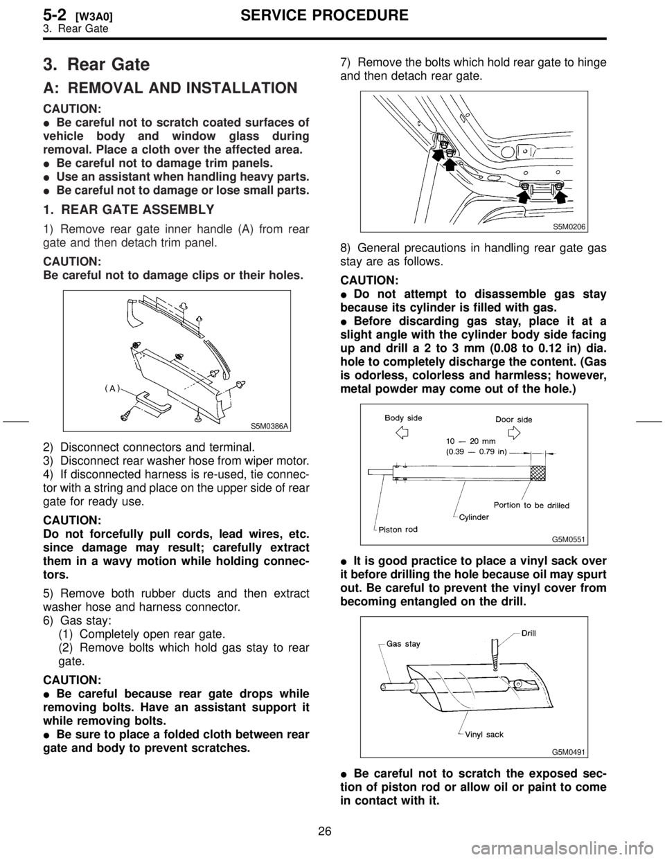
1) Remove rear gate inner handle (A) from rear
gate and then detach trim panel.
CAUTION:
Be careful not to damage clips or their holes.
S5M0386A
2) Disconnect connectors and terminal.
3) Disconnect rear washer hose from wiper motor.
4) If disconnected harness is re-used, tie connec-
tor with a string and place on the upper side of rear
gate for ready use.
CAUTION:
Do not forcefully pull cords, lead wires, etc.
since damage may result; carefully extract
them in a wavy motion while holding connec-
tors.
5) Remove both rubber ducts and then extract
washer hose and harness connector.
6) Gas stay:
(1) Completely open rear gate.
(2) Remove bolts which hold gas stay to rear
gate.
CAUTION:
IBe careful because rear gate drops while
removing bolts. Have an assistant support it
while removing bolts.
IBe sure to place a folded cloth between rear
gate and body to prevent scratches.7) Remove the bolts which hold rear gate to hinge
and then detach rear gate.
S5M0206
8) General precautions in handling rear gate gas
stay are as follows.
CAUTION:
IDo not attempt to disassemble gas stay
because its cylinder is filled with gas.
IBefore discarding gas stay, place it at a
slight angle with the cylinder body side facing
up and drilla2to3mm(0.08 to 0.12 in) dia.
hole to completely discharge the content. (Gas
is odorless, colorless and harmless; however,
metal powder may come out of the hole.)
G5M0551
IIt is good practice to place a vinyl sack over
it before drilling the hole because oil may spurt
out. Be careful to prevent the vinyl cover from
becoming entangled on the drill.
G5M0491
IBe careful not to scratch the exposed sec-
tion of piston rod or allow oil or paint to come
in contact with it.
26
5-2[W3A0]SERVICE PROCEDURE
3. Rear Gate
Page 274 of 345
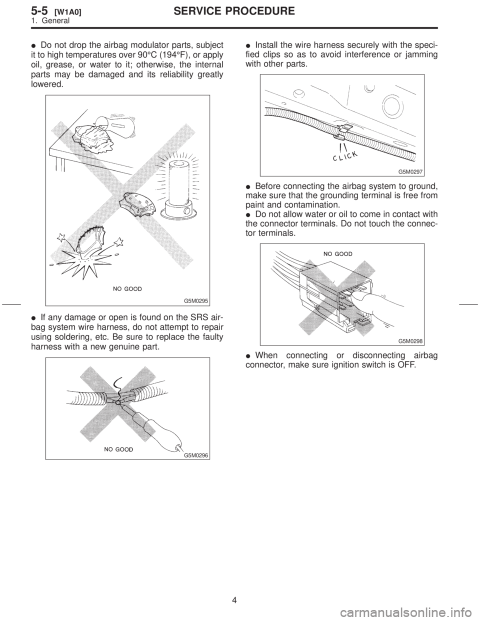
IDo not drop the airbag modulator parts, subject
it to high temperatures over 90ÉC (194ÉF), or apply
oil, grease, or water to it; otherwise, the internal
parts may be damaged and its reliability greatly
lowered.
G5M0295
IIf any damage or open is found on the SRS air-
bag system wire harness, do not attempt to repair
using soldering, etc. Be sure to replace the faulty
harness with a new genuine part.
G5M0296
IInstall the wire harness securely with the speci-
fied clips so as to avoid interference or jamming
with other parts.
G5M0297
IBefore connecting the airbag system to ground,
make sure that the grounding terminal is free from
paint and contamination.
IDo not allow water or oil to come in contact with
the connector terminals. Do not touch the connec-
tor terminals.
G5M0298
IWhen connecting or disconnecting airbag
connector, make sure ignition switch is OFF.
4
5-5[W1A0]SERVICE PROCEDURE
1. General
Page 275 of 345
2. Inspection and Replacement
Standards
A: VEHICLES WHICH BECOME
INVOLVED IN A COLLISION
If the vehicle equipped with an SRS airbag system
is damaged in a collision, the airbag system parts
must be checked and replaced in accordance with
the following standards:
IAfter faulty parts are replaced, the warning light
operation must be checked.
IWhen the ignition switch is turned ON, it lights
up for about 7 seconds and then it goes out for at
least 30 seconds.
IThe trouble code stored in memory must be
erased after the check.
B: AIRBAG MODULE (DRIVER AND
PASSENGER)
1. INSPECTION STANDARD
IThe vehicle damaged in a collision (regardless
of whether or not airbag is deployed).
IThe designated trouble code is output during
self-diagnosis.
2. REPLACEMENT STANDARD
IAirbag is deployed.
IThe pad surface is scratched or cracked.
IHarness and/or connector is deformed or
cracked, their circuits are broken, lead wire is
exposed, etc.
IMounting bracket is cracked or deformed.
IThe module surface is fouled with foreign mat-
ter. (grease, oil, water, cleaning solvent, etc.)
IAirbag module dropped to the floor/ground.
IAirbag module determined as faulty during self-
diagnosis.
C: AIRBAG MODULE (SIDE)
1. INSPECTION STANDARD
IThe vehicle damaged in a side collision (regard-
less of whether or not airbag is deployed).
IThe designated trouble code is output during
self-diagnosis.
2. REPLACEMENT STANDARD
ISide airbag is deployed.
IThe front seat assembly is damaged or
deformed.
IHarness and/or connector is deformed or
cracked, their circuits are broken, lead wire is
exposed, etc.
IMounting bracket is cracked or deformed.ISide airbag module determined as faulty during
self-diagnosis.
D: MAIN HARNESS
1. INSPECTION STANDARD
IA vehicle damaged in a collision (regardless of
whether or not airbag is deployed).
IThe designated trouble code is output during
self-diagnosis.
2. REPLACEMENT STANDARD
IHarness circuit is broken, lead wire is exposed,
corrugated tube is cracked, etc.
IConnector is scratched or cracked.
IThe designated trouble code is output during
self-diagnosis.
E: AIRBAG CONTROL MODULE
1. INSPECTION STANDARD
IA vehicle damaged in a collision (regardless of
whether or not airbag is deployed).
IThe designated trouble code is output during
self-diagnosis.
2. REPLACEMENT STANDARD
IControl module is cracked or deformed.
IMounting bracket is cracked or deformed.
IConnector is scratched or cracked.
IControl module dropped to the floor/ground.
IControl module determined as faulty during
diagnostics.
IFront or side airbag is deployed.
F: ROLL CONNECTOR
1. INSPECTION STANDARD
IA vehicle damaged in a collision (regardless of
whether or not airbag is deployed).
IThe designated trouble code is output during
self-diagnosis.
2. REPLACEMENT STANDARD
ICombination switch or steering roll connector is
deformed or cracked.
5
[W2F2]5-5SERVICE PROCEDURE
2. Inspection and Replacement Standards
Page 278 of 345
3. Airbag Module
A: REMOVAL AND INSTALLATION
CAUTION:
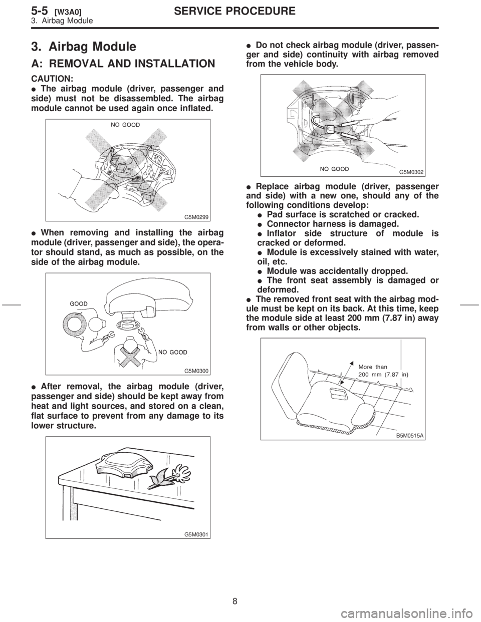
IThe airbag module (driver, passenger and
side) must not be disassembled. The airbag
module cannot be used again once inflated.
G5M0299
IWhen removing and installing the airbag
module (driver, passenger and side), the opera-
tor should stand, as much as possible, on the
side of the airbag module.
G5M0300
IAfter removal, the airbag module (driver,
passenger and side) should be kept away from
heat and light sources, and stored on a clean,
flat surface to prevent from any damage to its
lower structure.
G5M0301
IDo not check airbag module (driver, passen-
ger and side) continuity with airbag removed
from the vehicle body.
G5M0302
IReplace airbag module (driver, passenger
and side) with a new one, should any of the
following conditions develop:
IPad surface is scratched or cracked.
IConnector harness is damaged.
IInflator side structure of module is
cracked or deformed.
IModule is excessively stained with water,
oil, etc.
IModule was accidentally dropped.
IThe front seat assembly is damaged or
deformed.
IThe removed front seat with the airbag mod-
ule must be kept on its back. At this time, keep
the module side at least 200 mm (7.87 in) away
from walls or other objects.
B5M0515A
8
5-5[W3A0]SERVICE PROCEDURE
3. Airbag Module
Page 293 of 345
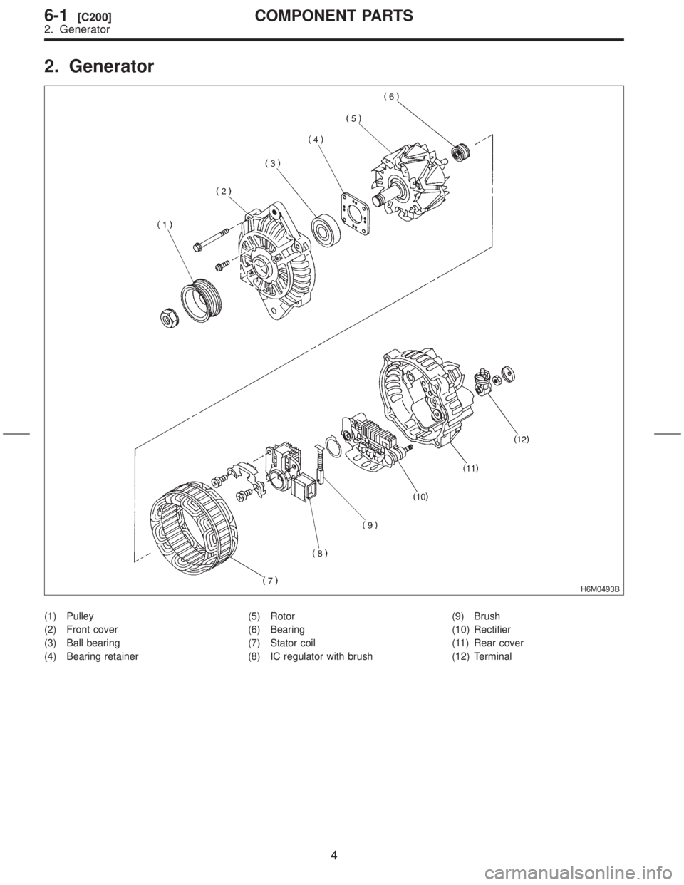
2. Generator
H6M0493B
(1) Pulley
(2) Front cover
(3) Ball bearing
(4) Bearing retainer(5) Rotor
(6) Bearing
(7) Stator coil
(8) IC regulator with brush(9) Brush
(10) Rectifier
(11) Rear cover
(12) Terminal
4
6-1[C200]COMPONENT PARTS
2. Generator
Page 295 of 345
![SUBARU FORESTER 1999 Service Repair Manual 1. Starter
A: REMOVAL AND INSTALLATION
1) Disconnect battery ground cable.
G6M0095
2) Remove air cleaner case and air intake duct.
<Ref. to 2-7 [W1A0].>
H2M2931
3) Remove air intake chamber stay.
S2M0 SUBARU FORESTER 1999 Service Repair Manual 1. Starter
A: REMOVAL AND INSTALLATION
1) Disconnect battery ground cable.
G6M0095
2) Remove air cleaner case and air intake duct.
<Ref. to 2-7 [W1A0].>
H2M2931
3) Remove air intake chamber stay.
S2M0](/manual-img/17/57427/w960_57427-294.png)
1. Starter
A: REMOVAL AND INSTALLATION
1) Disconnect battery ground cable.
G6M0095
2) Remove air cleaner case and air intake duct.
H2M2931
3) Remove air intake chamber stay.
S2M0900A
S2M0901A
4) Disconnect connector and terminal from starter.
S6M0002A
(A) Terminal
(B) Connector
5) Remove starter from transmission.
G2M0309
6) Install in the reverse order of removal.
Tightening torque:
50
±4 N´m (5.1±0.4 kg-m, 37±2.9 ft-lb)
G2M0309
B: TEST
1. SWITCH ASSEMBLY OPERATION
1) Connect terminal S of switch assembly to posi-
tive terminal of battery with a lead wire, and starter
body to ground terminal of battery. Pinion should
be forced endwise on shaft.
CAUTION:
With pinion forced endwise on shaft, starter
motor can sometimes rotate because current
flows, through pull-in coil, to motor. This is not
a problem.
6
6-1[W1A0]SERVICE PROCEDURE
1. Starter
Page 300 of 345
2. YOKE
Make sure pole is set in position.
3. OVERRUNNING CLUTCH
Inspect teeth of pinion for wear and damage.
Replace if it is damaged. Rotate pinion in direction
of rotation (counterclockwise). It should rotate
smoothly. But in opposite direction, it should be
locked.
CAUTION:
Do not clean overrunning clutch with oil to pre-
vent grease from flowing out.
4. BRUSH AND BRUSH HOLDER
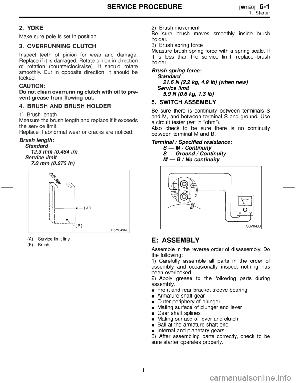
1) Brush length
Measure the brush length and replace if it exceeds
the service limit.
Replace if abnormal wear or cracks are noticed.
Brush length:
Standard
12.3 mm (0.484 in)
Service limit
7.0 mm (0.276 in)
H6M0496C
(A) Service limit line
(B) Brush
2) Brush movement
Be sure brush moves smoothly inside brush
holder.
3) Brush spring force
Measure brush spring force with a spring scale. If
it is less than the service limit, replace brush
holder.
Brush spring force:
Standard
21.6 N (2.2 kg, 4.9 lb) (when new)
Service limit
5.9 N (0.6 kg, 1.3 lb)
5. SWITCH ASSEMBLY
Be sure there is continuity between terminals S
and M, and between terminal S and ground. Use
a circuit tester (set in ªohmº).
Also check to be sure there is no continuity
between terminal M and B.
Terminal / Specified resistance:
SÐM/Continuity
S Ð Ground / Continuity
MÐB/Nocontinuity
S6M0403
E: ASSEMBLY
Assemble in the reverse order of disassembly. Do
the following:
1) Carefully assemble all parts in the order of
assembly and occasionally inspect nothing has
been overlooked.
2) Apply grease to the following parts during
assembly.
IFront and rear bracket sleeve bearing
IArmature shaft gear
IOuter periphery of plunger
IMating surface of plunger and lever
IGear shaft splines
IMating surface of lever and clutch
IBall at the armature shaft end
IInternal and planetary gears
3) After assembling parts correctly, check to be
sure starter operates properly.
11
[W1E0]6-1SERVICE PROCEDURE
1. Starter