Page 310 of 345

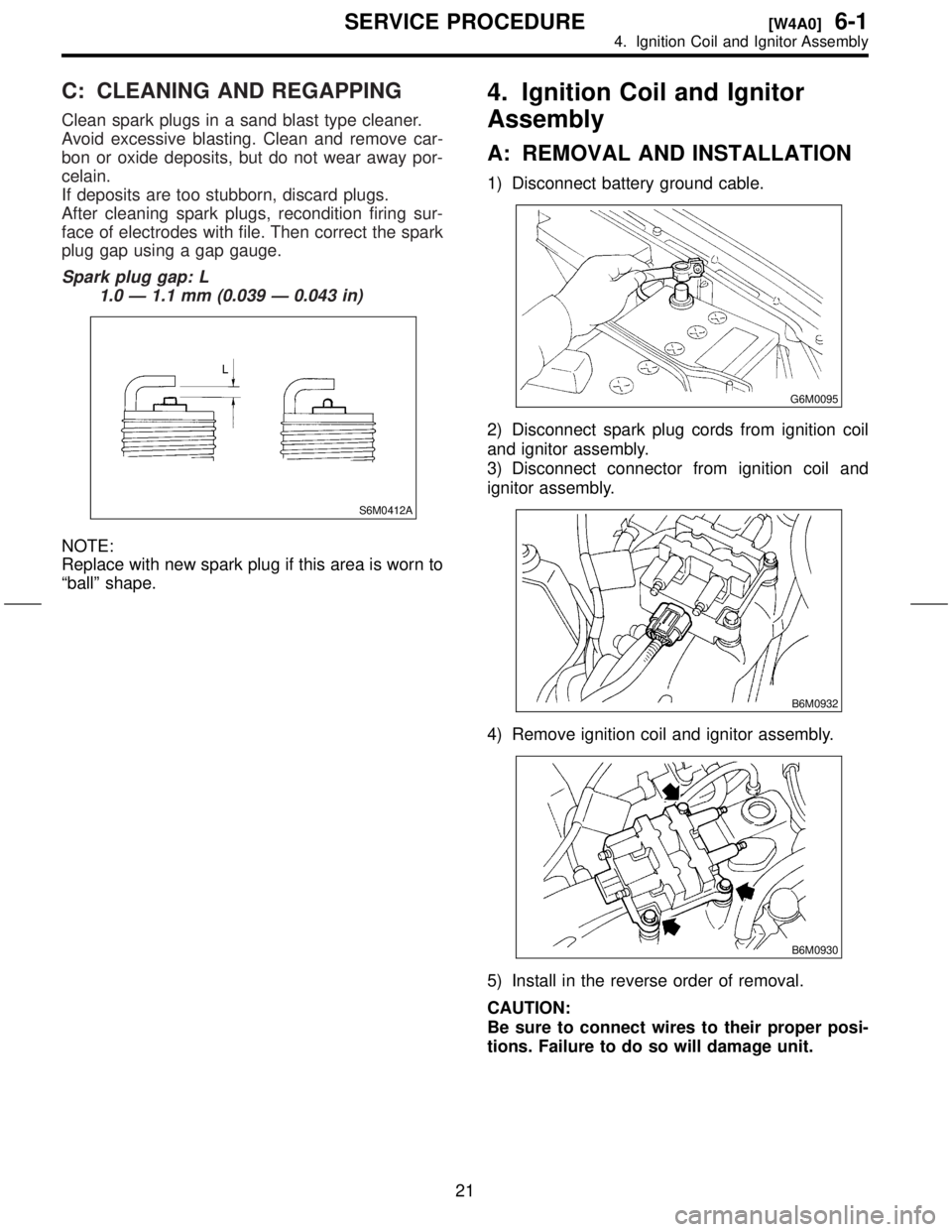
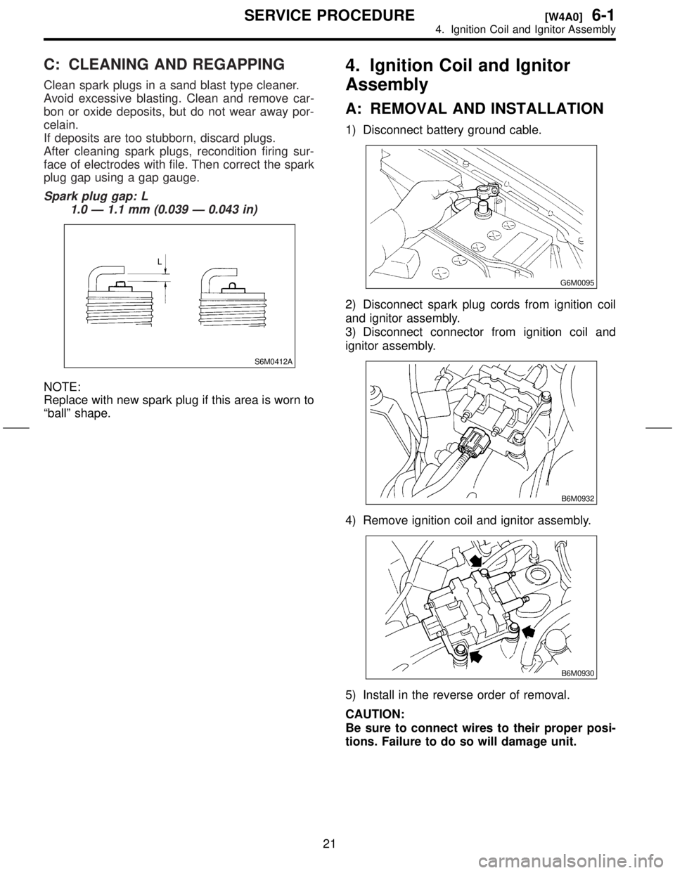
7) Install in the reverse order of removal.
Tightening torque (Spark plug):
20.6
±2.9 N´m (2.10±0.30 kg-m, 15.19±2.14
ft-lb)
CAUTION:
The above torque should be only applied to
new spark plugs without oil on their threads.
In case their threads are lubricated, the torque
should be reduced by approximately 1/3 of the
specified torque in order to avoid over-stress-
ing.
B: INSPECTION
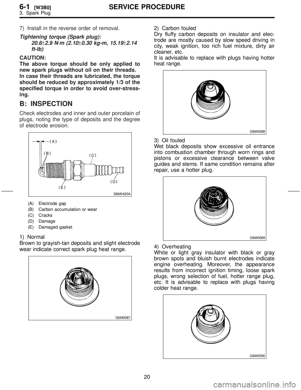
Check electrodes and inner and outer porcelain of
plugs, noting the type of deposits and the degree
of electrode erosion.
S6M0420A
(A) Electrode gap
(B) Carbon accumulation or wear
(C) Cracks
(D) Damage
(E) Damaged gasket
1) Normal
Brown to grayish-tan deposits and slight electrode
wear indicate correct spark plug heat range.
G6M0087
2) Carbon fouled
Dry fluffy carbon deposits on insulator and elec-
trode are mostly caused by slow speed driving in
city, weak ignition, too rich fuel mixture, dirty air
cleaner, etc.
It is advisable to replace with plugs having hotter
heat range.
G6M0088
3) Oil fouled
Wet black deposits show excessive oil entrance
into combustion chamber through worn rings and
pistons or excessive clearance between valve
guides and stems. If same condition remains after
repair, use a hotter plug.
G6M0089
4) Overheating
White or light gray insulator with black or gray
brown spots and bluish burnt electrodes indicate
engine overheating. Moreover, the appearance
results from incorrect ignition timing, loose spark
plugs, wrong selection of fuel, hotter range plug,
etc. It is advisable to replace with plugs having
colder heat range.
G6M0090
20
6-1[W3B0]SERVICE PROCEDURE
3. Spark Plug
Page 311 of 345

C: CLEANING AND REGAPPING
Clean spark plugs in a sand blast type cleaner.
Avoid excessive blasting. Clean and remove car-
bon or oxide deposits, but do not wear away por-
celain.
If deposits are too stubborn, discard plugs.
After cleaning spark plugs, recondition firing sur-
face of electrodes with file. Then correct the spark
plug gap using a gap gauge.
Spark plug gap: L
1.0 Ð 1.1 mm (0.039 Ð 0.043 in)
S6M0412A
NOTE:
Replace with new spark plug if this area is worn to
ªballº shape.
4. Ignition Coil and Ignitor
Assembly
A: REMOVAL AND INSTALLATION
1) Disconnect battery ground cable.
G6M0095
2) Disconnect spark plug cords from ignition coil
and ignitor assembly.
3) Disconnect connector from ignition coil and
ignitor assembly.
B6M0932
4) Remove ignition coil and ignitor assembly.
B6M0930
5) Install in the reverse order of removal.
CAUTION:
Be sure to connect wires to their proper posi-
tions. Failure to do so will damage unit.
21
[W4A0]6-1SERVICE PROCEDURE
4. Ignition Coil and Ignitor Assembly
Page 312 of 345

C: CLEANING AND REGAPPING
Clean spark plugs in a sand blast type cleaner.
Avoid excessive blasting. Clean and remove car-
bon or oxide deposits, but do not wear away por-
celain.
If deposits are too stubborn, discard plugs.
After cleaning spark plugs, recondition firing sur-
face of electrodes with file. Then correct the spark
plug gap using a gap gauge.
Spark plug gap: L
1.0 Ð 1.1 mm (0.039 Ð 0.043 in)
S6M0412A
NOTE:
Replace with new spark plug if this area is worn to
ªballº shape.
4. Ignition Coil and Ignitor
Assembly
A: REMOVAL AND INSTALLATION
1) Disconnect battery ground cable.
G6M0095
2) Disconnect spark plug cords from ignition coil
and ignitor assembly.
3) Disconnect connector from ignition coil and
ignitor assembly.
B6M0932
4) Remove ignition coil and ignitor assembly.
B6M0930
5) Install in the reverse order of removal.
CAUTION:
Be sure to connect wires to their proper posi-
tions. Failure to do so will damage unit.
21
[W4A0]6-1SERVICE PROCEDURE
4. Ignition Coil and Ignitor Assembly
Page 313 of 345
B: INSPECTION
Using accurate tester, inspect the following items,
and replace if defective.
1) Primary resistance
2) Secondary coil resistance
CAUTION:
If the resistance is extremely low, this indicates
the presence of a short-circuit.
Specified resistance:
[Primary side]
Between terminal No. 1 and No. 2
0.73
W±10%
Between terminal No. 2 and No. 4
0.73
W±10%
B6M0931
[Secondary side]
Between (A) and (B)
12.8 k
W±15%
Between (C) and (D)
12.8 k
W±15%
3) Insulation between primary terminal and case:
10 MWor more.
B6M0773I
5. Spark Plug Cord
A: INSPECTION
Check for:
1) Damage to cords, deformation, burning or rust
formation of terminals
2) Resistance values of cords
Resistance value:
#1 cord: 7.40 Ð 17.27
#2 cord: 6.24 Ð 14.56
#3 cord: 6.54 Ð 15.25
#4 cord: 6.59 Ð 15.37
S6M0337
22
6-1[W4B0]SERVICE PROCEDURE
5. Spark Plug Cord
Page 315 of 345

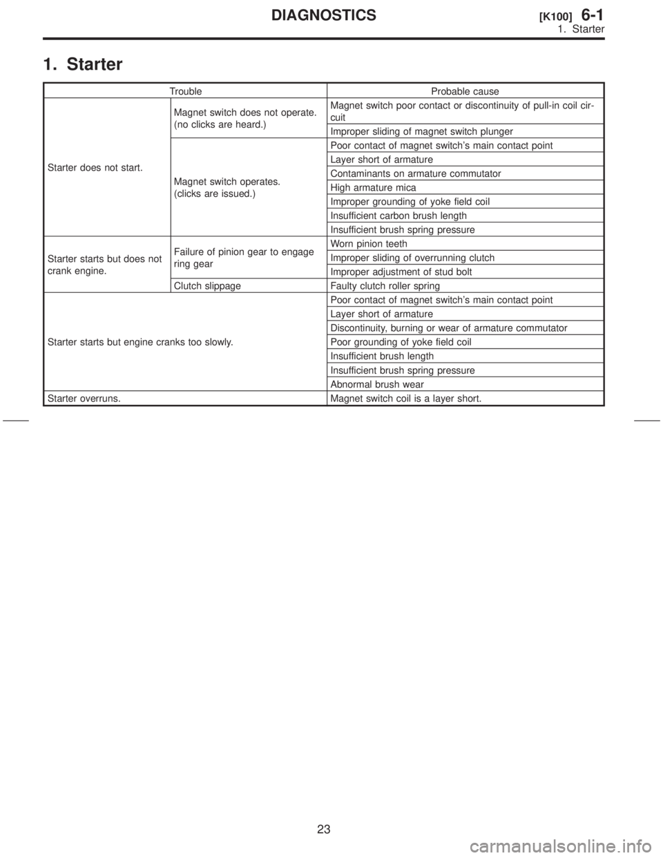
1. Starter
Trouble Probable cause
Starter does not start.Magnet switch does not operate.
(no clicks are heard.)Magnet switch poor contact or discontinuity of pull-in coil cir-
cuit
Improper sliding of magnet switch plunger
Magnet switch operates.
(clicks are issued.)Poor contact of magnet switch's main contact point
Layer short of armature
Contaminants on armature commutator
High armature mica
Improper grounding of yoke field coil
Insufficient carbon brush length
Insufficient brush spring pressure
Starter starts but does not
crank engine.Failure of pinion gear to engage
ring gearWorn pinion teeth
Improper sliding of overrunning clutch
Improper adjustment of stud bolt
Clutch slippage Faulty clutch roller spring
Starter starts but engine cranks too slowly.Poor contact of magnet switch's main contact point
Layer short of armature
Discontinuity, burning or wear of armature commutator
Poor grounding of yoke field coil
Insufficient brush length
Insufficient brush spring pressure
Abnormal brush wear
Starter overruns. Magnet switch coil is a layer short.
23
[K100]6-1DIAGNOSTICS
1. Starter
Page 317 of 345
1.
BatteryT
Capacity
Reverse
Cold
Combination Speedometer
T
Fuel
T
T
2
Charge 2
Oil 2
ABS 2
CHECK
\(Malfunction 12
HI-beam 2
Door
Seat 2
Brake 2
FWD 2
AIRBAG 2
Meter 2V\3203W
A 2
Security
Low 2
Headlight 12
Front 2V\3202
Front 1
Rear T
2
T 2V\3202
Back-up 2V\3202
License 1
High-mounted 2V\3201
Room 1
Spot 1
Luggage 1
Front 2V\3205less
Rear 2V\3204less
Front Pump
Input
2V\3203less
Rear Pump
Input
2V\3203less
Horn 12
Accessory 2
Rear
defogger Input
2
Indicator 2V\3205
Cargo 2
2
6-2[S100]SPECIFICA
1.
Page 327 of 345

B: REMOVAL AND INSTALLATION
1. BLADE
1) Pull out blade following the arrow direction,
from arm while pushing up locking clip (A).
B6M0107B
2) Install in the reverse order of removal.
2. WIPER ARM
1) Open front hood.
2) Remove cap. Remove the nut which secure
wiper arm, and remove wiper arm.
S6M0050
3) Install in the reverse order of removal.
NOTE:
Remove metal sludge from the wiper arm fixture
before installing it.
Tightening torque:
20
±3 N´m (2.0±0.3 kg-m, 14.5±2.2 ft-lb)
3. WIPER MOTOR AND LINK
1) Disconnect ground cable from battery.
2) Detach cowl panel.
NOTE:
Apply silicone oil or soap water to both sides of
cowl net to facilitate removal.3) Disconnect electric connector, and remove
motor attaching bolts.
Tightening torque:
5.9
±1.5 N´m (0.6±0.15 kg-m, 4.3±1.1 ft-lb)
S6M0051
4) Remove cowl cover.
5) Remove nut securing motor link on the back
side of motor.
Tightening torque:
15
±3 N´m (1.5±0.3 kg-m, 11±2.2 ft-lb)
S6M0052
6) Remove bolts which secure sleeve unit.
Tightening torque:
5.9
±1.5 N´m (0.6±0.15 kg-m, 4.3±1.1 ft-lb)
S6M0053
9
[W5B3]6-2SERVICE PROCEDURE
5. Front Wiper and Washer
Page 332 of 345
3. REAR WIPER RELAY
1) Connect battery to terminal No. 1 and ground
terminal No. 2.
2) Check continuity between terminals.
When current
flowsBetween terminals
No. 3 and No. 4Continuity does
not exist.
Between terminals
No. 3 and No. 5Continuity exists.
When current
does not flowBetween terminals
No. 3 and No. 4Continuity exists.
Between terminals
No. 3 and No. 5Continuity does
not exist.
Between terminals
No. 1 and No. 2Continuity exists.
S6M0075B
7. Rear Window Defogger
A: INSPECTION
1. HEAT WIRES
1) Start the engine so that battery is being
charged.
2) Turn defogger switch to ON.
3) Check each heat wire at its center position for
discontinuity by setting direct current voltmeter.
NOTE:
INormal indication is about 6 volts.
G6M0135
IWhen measuring voltage, wind a piece of tin foil
around the tip of the tester probe and press the foil
against the wire with your finger.
G6M0136
14
6-2[W6C3]SERVICE PROCEDURE
7. Rear Window Defogger