1999 SUBARU FORESTER arm
[x] Cancel search: armPage 116 of 345
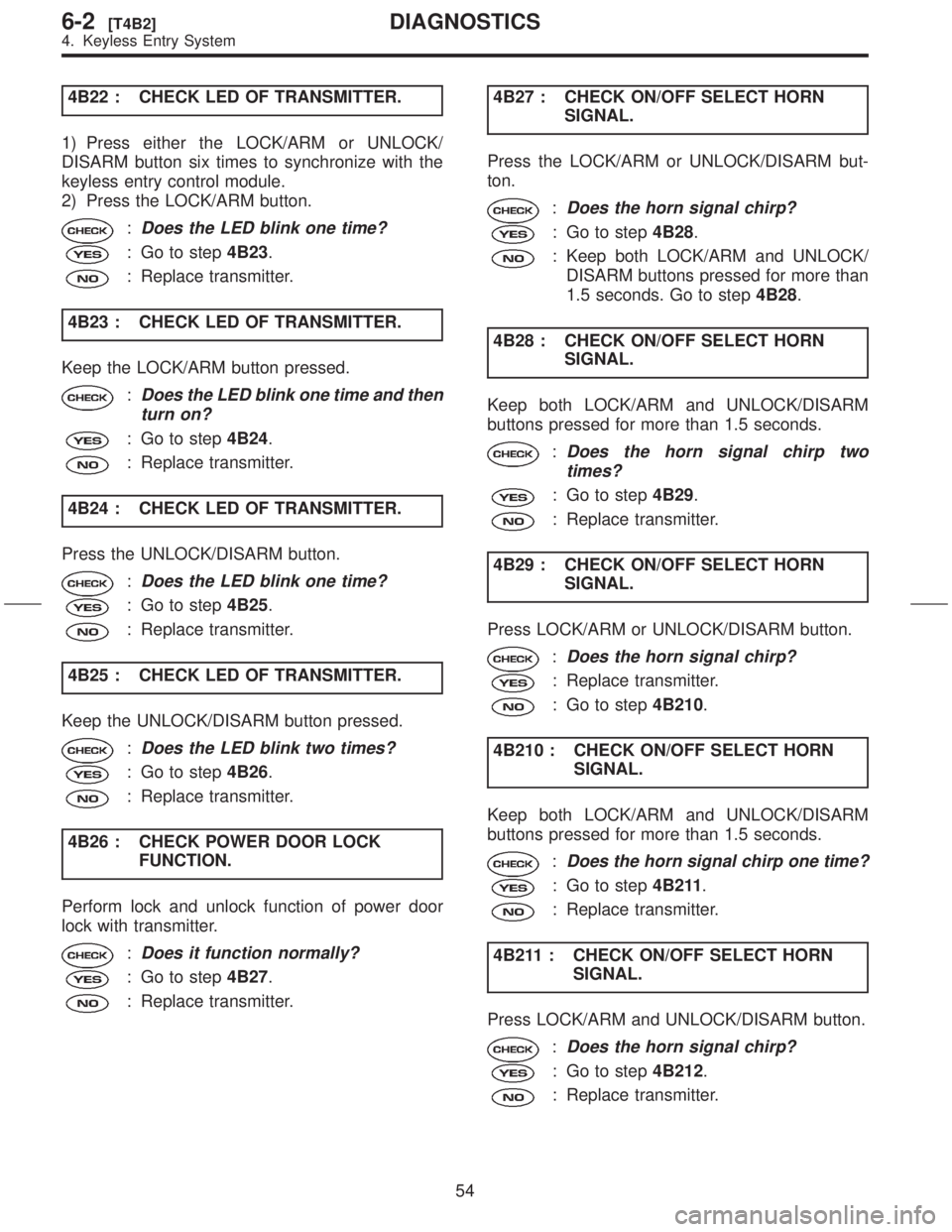
4B22 : CHECK LED OF TRANSMITTER.
1) Press either the LOCK/ARM or UNLOCK/
DISARM button six times to synchronize with the
keyless entry control module.
2) Press the LOCK/ARM button.
:Does the LED blink one time?
: Go to step4B23.
: Replace transmitter.
4B23 : CHECK LED OF TRANSMITTER.
Keep the LOCK/ARM button pressed.
:Does the LED blink one time and then
turn on?
: Go to step4B24.
: Replace transmitter.
4B24 : CHECK LED OF TRANSMITTER.
Press the UNLOCK/DISARM button.
:Does the LED blink one time?
: Go to step4B25.
: Replace transmitter.
4B25 : CHECK LED OF TRANSMITTER.
Keep the UNLOCK/DISARM button pressed.
:Does the LED blink two times?
: Go to step4B26.
: Replace transmitter.
4B26 : CHECK POWER DOOR LOCK
FUNCTION.
Perform lock and unlock function of power door
lock with transmitter.
:Does it function normally?
: Go to step4B27.
: Replace transmitter.4B27 : CHECK ON/OFF SELECT HORN
SIGNAL.
Press the LOCK/ARM or UNLOCK/DISARM but-
ton.
:Does the horn signal chirp?
: Go to step4B28.
: Keep both LOCK/ARM and UNLOCK/
DISARM buttons pressed for more than
1.5 seconds. Go to step4B28.
4B28 : CHECK ON/OFF SELECT HORN
SIGNAL.
Keep both LOCK/ARM and UNLOCK/DISARM
buttons pressed for more than 1.5 seconds.
:Does the horn signal chirp two
times?
: Go to step4B29.
: Replace transmitter.
4B29 : CHECK ON/OFF SELECT HORN
SIGNAL.
Press LOCK/ARM or UNLOCK/DISARM button.
:Does the horn signal chirp?
: Replace transmitter.
: Go to step4B210.
4B210 : CHECK ON/OFF SELECT HORN
SIGNAL.
Keep both LOCK/ARM and UNLOCK/DISARM
buttons pressed for more than 1.5 seconds.
:Does the horn signal chirp one time?
: Go to step4B211.
: Replace transmitter.
4B211 : CHECK ON/OFF SELECT HORN
SIGNAL.
Press LOCK/ARM and UNLOCK/DISARM button.
:Does the horn signal chirp?
: Go to step4B212.
: Replace transmitter.
54
6-2[T4B2]DIAGNOSTICS
4. Keyless Entry System
Page 122 of 345
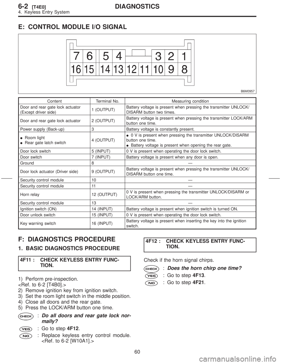
E: CONTROL MODULE I/O SIGNAL
B6M0957
Content Terminal No. Measuring condition
Door and rear gate lock actuator
(Except driver side)1 (OUTPUT)Battery voltage is present when pressing the transmitter UNLOCK/
DISARM button two times.
Door and rear gate lock actuator 2 (OUTPUT)Battery voltage is present when pressing the transmitter LOCK/ARM
button one time.
Power supply (Back-up) 3 Battery voltage is constantly present.
IRoom light
IRear gate latch switch4 (OUTPUT)I0 V is present when pressing the transmitter UNLOCK/DISARM
button one time.
IBattery voltage is present when opening the rear gate.
Door lock switch 5 (INPUT) 0 V is present when operating the door lock switch.
Door switch 7 (INPUT) Battery voltage is present when any door is open.
Ground 8 Ð
Door lock actuator (Driver side) 9 (OUTPUT)Battery voltage is present when pressing the transmitter UNLOCK/
DISARM button one time.
Security control module 10 Ð
Security control module 11 Ð
Horn relay 12 (OUTPUT)0 V is present when pressing the transmitter UNLOCK/DISARM or
LOCK/ARM button.
Security control module 13 Ð
Ignition switch (ON) 14 (INPUT) Battery voltage is present when ignition switch is turned ON.
Door unlock switch 15 (INPUT) 0 V is present when operating the door lock switch.
Key warning switch 16 (INPUT)Battery voltage is present when inserting the key into the ignition
switch.
F: DIAGNOSTICS PROCEDURE
1. BASIC DIAGNOSTICS PROCEDURE
4F11 : CHECK KEYLESS ENTRY FUNC-
TION.
1) Perform pre-inspection.
2) Remove ignition key from ignition switch.
3) Set the room light switch in the middle position.
4) Close all doors and the rear gate.
5) Press the LOCK/ARM button one time.
:Do all doors and rear gate lock nor-
mally?
: Go to step4F12.
: Replace keyless entry control module.
TION.
Check if the horn signal chirps.
:Does the horn chirp one time?
: Go to step4F13.
: Go to step4F21.
60
6-2[T4E0]DIAGNOSTICS
4. Keyless Entry System
Page 123 of 345
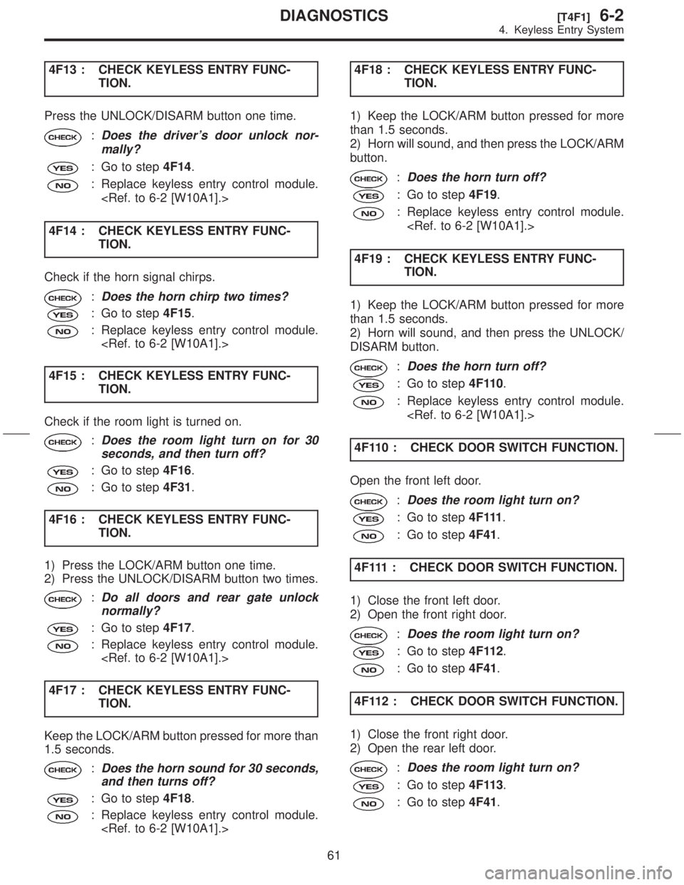
4F13 : CHECK KEYLESS ENTRY FUNC-
TION.
Press the UNLOCK/DISARM button one time.
:Does the driver's door unlock nor-
mally?
: Go to step4F14.
: Replace keyless entry control module.
4F14 : CHECK KEYLESS ENTRY FUNC-
TION.
Check if the horn signal chirps.
:Does the horn chirp two times?
: Go to step4F15.
: Replace keyless entry control module.
4F15 : CHECK KEYLESS ENTRY FUNC-
TION.
Check if the room light is turned on.
:Does the room light turn on for 30
seconds, and then turn off?
: Go to step4F16.
: Go to step4F31.
4F16 : CHECK KEYLESS ENTRY FUNC-
TION.
1) Press the LOCK/ARM button one time.
2) Press the UNLOCK/DISARM button two times.
:Do all doors and rear gate unlock
normally?
: Go to step4F17.
: Replace keyless entry control module.
4F17 : CHECK KEYLESS ENTRY FUNC-
TION.
Keep the LOCK/ARM button pressed for more than
1.5 seconds.
:Does the horn sound for 30 seconds,
and then turns off?
: Go to step4F18.
: Replace keyless entry control module.
TION.
1) Keep the LOCK/ARM button pressed for more
than 1.5 seconds.
2) Horn will sound, and then press the LOCK/ARM
button.
:Does the horn turn off?
: Go to step4F19.
: Replace keyless entry control module.
4F19 : CHECK KEYLESS ENTRY FUNC-
TION.
1) Keep the LOCK/ARM button pressed for more
than 1.5 seconds.
2) Horn will sound, and then press the UNLOCK/
DISARM button.
:Does the horn turn off?
: Go to step4F110.
: Replace keyless entry control module.
4F110 : CHECK DOOR SWITCH FUNCTION.
Open the front left door.
:Does the room light turn on?
: Go to step4 F 111.
: Go to step4F41.
4F111 : CHECK DOOR SWITCH FUNCTION.
1) Close the front left door.
2) Open the front right door.
:Does the room light turn on?
: Go to step4F112.
: Go to step4F41.
4F112 : CHECK DOOR SWITCH FUNCTION.
1) Close the front right door.
2) Open the rear left door.
:Does the room light turn on?
: Go to step4F113.
: Go to step4F41.
61
[T4F1]6-2DIAGNOSTICS
4. Keyless Entry System
Page 125 of 345
2. DIAGNOSTICS ITEM 1
4F21 : SELECT HORN SIGNAL OPERA-
TION.
Keep both LOCK/ARM and UNLOCK/DISARM
buttons pressed for more than 1.5 seconds.
:Does the horn chirp one time?
: Go to step4F22.
: Replace keyless entry control module.
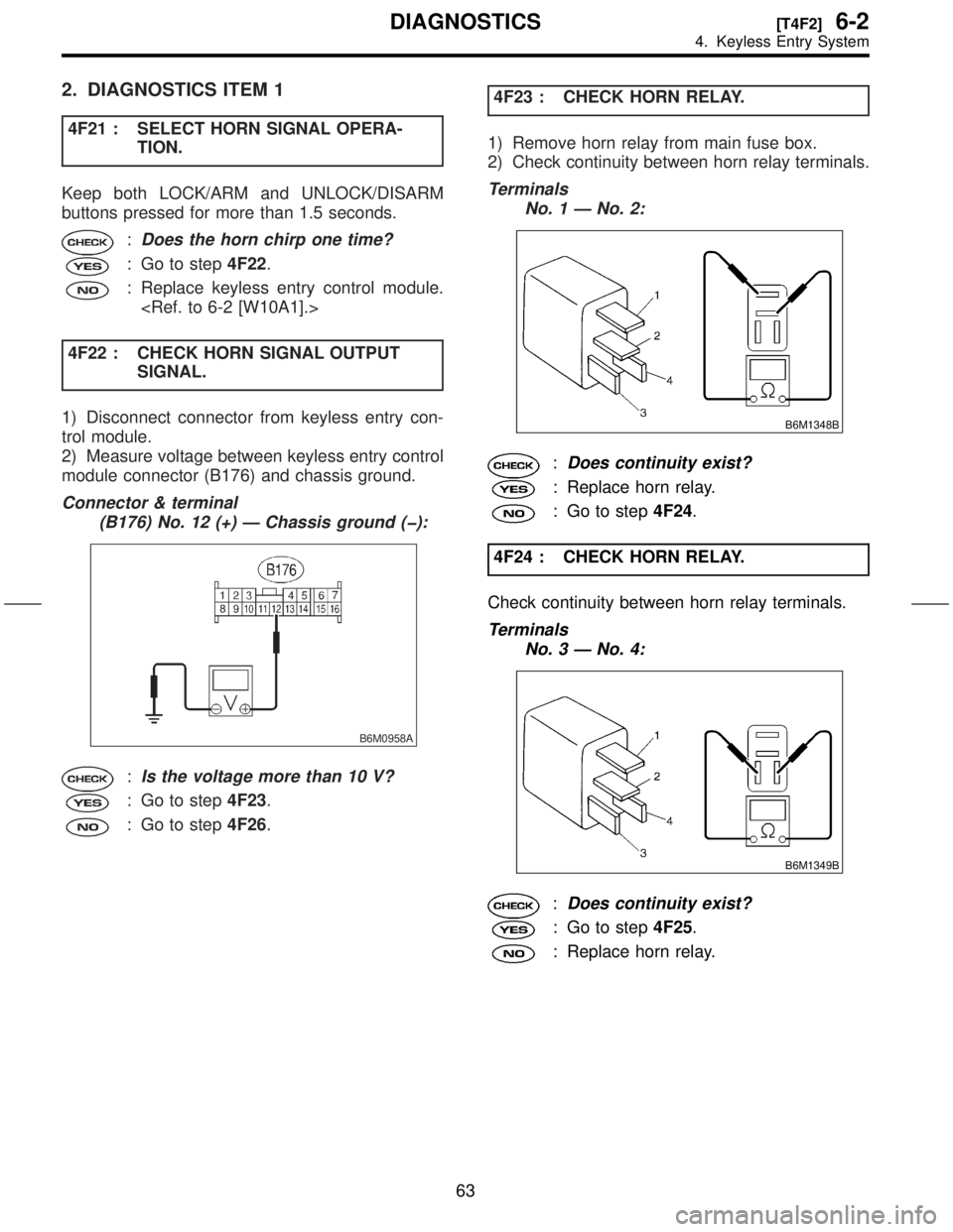
4F22 : CHECK HORN SIGNAL OUTPUT
SIGNAL.
1) Disconnect connector from keyless entry con-
trol module.
2) Measure voltage between keyless entry control
module connector (B176) and chassis ground.
Connector & terminal
(B176) No. 12 (+) Ð Chassis ground (þ):
B6M0958A
:Is the voltage more than 10 V?
: Go to step4F23.
: Go to step4F26.4F23 : CHECK HORN RELAY.
1) Remove horn relay from main fuse box.
2) Check continuity between horn relay terminals.
Terminals
No. 1 Ð No. 2:
B6M1348B
:Does continuity exist?
: Replace horn relay.
: Go to step4F24.
4F24 : CHECK HORN RELAY.
Check continuity between horn relay terminals.
Terminals
No. 3 Ð No. 4:
B6M1349B
:Does continuity exist?
: Go to step4F25.
: Replace horn relay.
63
[T4F2]6-2DIAGNOSTICS
4. Keyless Entry System
Page 133 of 345

C: ELECTRICAL COMPONENTS LOCATION
S6M0454A
(1) Horn
(2) Keyless entry control module
(3) Security control module (under
console box)
(4) Security indicator light (in combi-
nation meter)(5) Horn relay (in main fuse box)
(6) Rear gate latch switch
(7) Interrupt relay (behind the fuse
box)
(8) Door switch(9) Passive arm connector (on driver
side front lower pillar)
71
[T5C0]6-2DIAGNOSTICS
5. Security System
Page 136 of 345
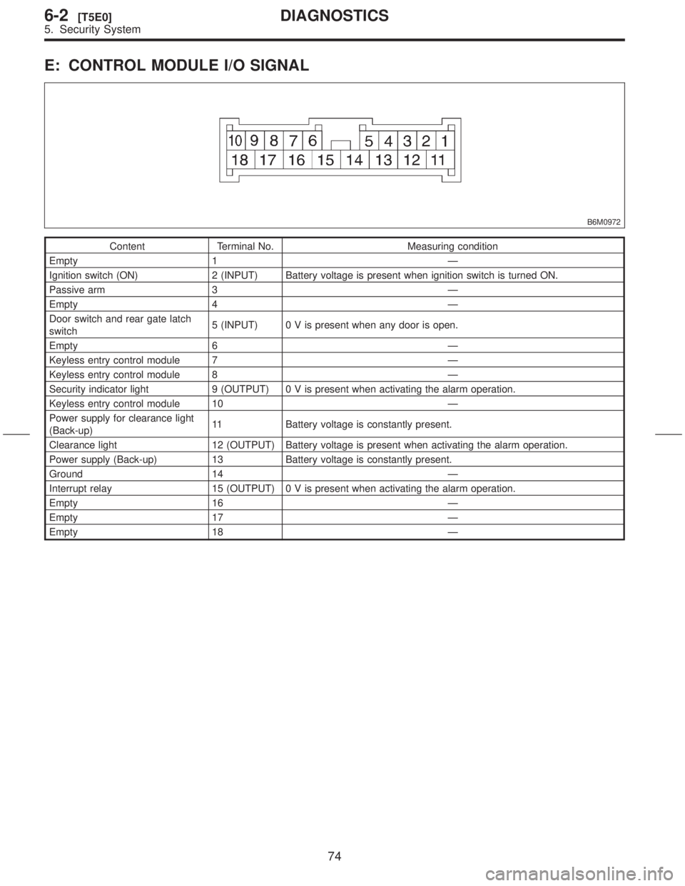
E: CONTROL MODULE I/O SIGNAL
B6M0972
Content Terminal No. Measuring condition
Empty 1 Ð
Ignition switch (ON) 2 (INPUT) Battery voltage is present when ignition switch is turned ON.
Passive arm 3 Ð
Empty 4 Ð
Door switch and rear gate latch
switch5 (INPUT) 0 V is present when any door is open.
Empty 6 Ð
Keyless entry control module 7 Ð
Keyless entry control module 8 Ð
Security indicator light 9 (OUTPUT) 0 V is present when activating the alarm operation.
Keyless entry control module 10 Ð
Power supply for clearance light
(Back-up)11 Battery voltage is constantly present.
Clearance light 12 (OUTPUT) Battery voltage is present when activating the alarm operation.
Power supply (Back-up) 13 Battery voltage is constantly present.
Ground 14 Ð
Interrupt relay 15 (OUTPUT) 0 V is present when activating the alarm operation.
Empty 16 Ð
Empty 17 Ð
Empty 18 Ð
74
6-2[T5E0]DIAGNOSTICS
5. Security System
Page 137 of 345
![SUBARU FORESTER 1999 Service Repair Manual F: DIAGNOSTICS PROCEDURE
1. BASIC DIAGNOSTICS PROCEDURE
5F11 : CHECK SECURITY SYSTEM FUNC-
TION.
1) Perform basic diagnostics procedure of keyless
entry system. <Ref. to 6-2 [T4F1].>
2) Perform pre-in](/manual-img/17/57427/w960_57427-136.png "SUBARU FORESTER 1999 Service Repair Manual F: DIAGNOSTICS PROCEDURE
1. BASIC DIAGNOSTICS PROCEDURE
5F11 : CHECK SECURITY SYSTEM FUNC-
TION.
1) Perform basic diagnostics procedure of keyless
entry system. <Ref. to 6-2 [T4F1].>
2) Perform pre-in")
F: DIAGNOSTICS PROCEDURE
1. BASIC DIAGNOSTICS PROCEDURE
5F11 : CHECK SECURITY SYSTEM FUNC-
TION.
1) Perform basic diagnostics procedure of keyless
entry system.
2) Perform pre-inspection.
3) Open all windows.
4) Remove ignition key from ignition switch.
5) Set the room light switch in the middle position.
6) Close all doors and the rear gate.
7) Press the LOCK/ARM button one time.
:Does the clearance light blink one
time?
: Go to step5F12.
: Go to step5F21.
5F12 : CHECK SECURITY SYSTEM FUNC-
TION.
Check if the security indicator light blinks.
:Does the security indicator light blink
every 2 seconds?
: Go to step5F13.
: Go to step5F31.
5F13 : CHECK SECURITY SYSTEM FUNC-
TION.
Press the UNLOCK/DISARM button one time.
:Does the clearance light blink two
times?
: Go to step5F14.
: Replace security control module.
5F14 : CHECK SECURITY SYSTEM FUNC-
TION.
Check if the room light activates.
:Does the room light turn on for 30
seconds and then turn off?
: Go to step5F15.
: Replace security control module.
TION.
1) Unlock all doors with door locking switch in the
front door.
2) Open the front left door.
:Does the security indicator light blink
every 1/8 seconds?
: Go to step5F16.
: Go to step5F41.
5F16 : CHECK SECURITY SYSTEM FUNC-
TION.
Check if the clearance light activates.
:Does the clearance light blinking
remain?
: Go to step5F17.
: Replace security control module.
5F17 : CHECK SECURITY SYSTEM FUNC-
TION.
Check if the horn activates.
:Does the horn sound remain?
: Go to step5F18.
: Replace security control module.
5F18 : CHECK SECURITY SYSTEM FUNC-
TION.
Turn on starter.
:Does the starter motor activate?
: Go to step5F51.
: Go to step5F19.
5F19 : CHECK SECURITY SYSTEM FUNC-
TION.
Close the front left door.
:Does the horn sound and clearance
light blinking deactivate, and starter
motor activate after approximately 30
seconds?
: Go to step5F110.
: Replace security control module.
75
[T5F1]6-2DIAGNOSTICS
5. Security System
Page 138 of 345
5F110 : CHECK SECURITY SYSTEM FUNC-
TION.
Check if the security indicator light activates.
:Does the security indicator light blink
every 2 seconds?
: Go to step5 F 111.
: Replace security control module.
5F111 : CHECK SECURITY SYSTEM FUNC-
TION.
Open the front right door.
:Does the security indicator light blink
every 1/8 seconds, the horn sound,
the clearance light blink, and the
starter motor deactivate?
: Go to step5F112.
: Go to step5F61.
5F112 : CHECK SECURITY SYSTEM FUNC-
TION.
Press the UNLOCK/DISARM button.
:Does the security indicator light
blink, the horn and clearance light
deactivate, and the starter motor acti-
vate?
: Go to step5F113.
: Replace security control module.
5F113 : CHECK SECURITY SYSTEM FUNC-
TION.
1) Close the front right door.
2) Press the LOCK/ARM button.
3) Open the rear left door.
:Does the security indicator light blink
every 1/8 seconds, the horn sound,
the clearance light blink, and the
starter motor deactivate?
: Go to step5F114.
: Go to step5F71.5F114 : CHECK SECURITY SYSTEM FUNC-
TION.
1) Close the rear left door.
2) Open the rear right door.
:Does the security indicator light blink
every 1/8 seconds, the horn sound,
the clearance light blink, and the
starter motor deactivate?
: Go to step5F115.
: Go to step5F81.
5F115 : CHECK SECURITY SYSTEM FUNC-
TION.
1) Close the rear right door.
2) Open the rear gate.
:Does the security indicator light blink
every 1/8 seconds, the horn sound,
the clearance light blink, and the
starter motor deactivate?
: Go to step5F116.
: Go to step5F91.
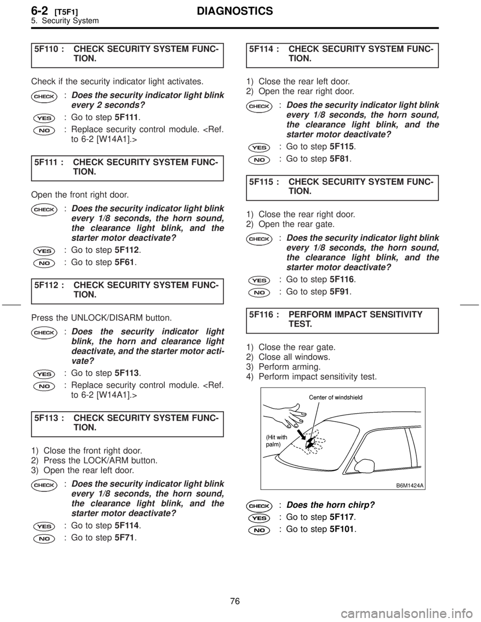
5F116 : PERFORM IMPACT SENSITIVITY
TEST.
1) Close the rear gate.
2) Close all windows.
3) Perform arming.
4) Perform impact sensitivity test.
B6M1424A
:Does the horn chirp?
: Go to step5F117.
: Go to step5F101.
76
6-2[T5F1]DIAGNOSTICS
5. Security System