Page 107 of 345

3H57 : CHECK CRUISE CONTROL COM-
MAND SWITCH.
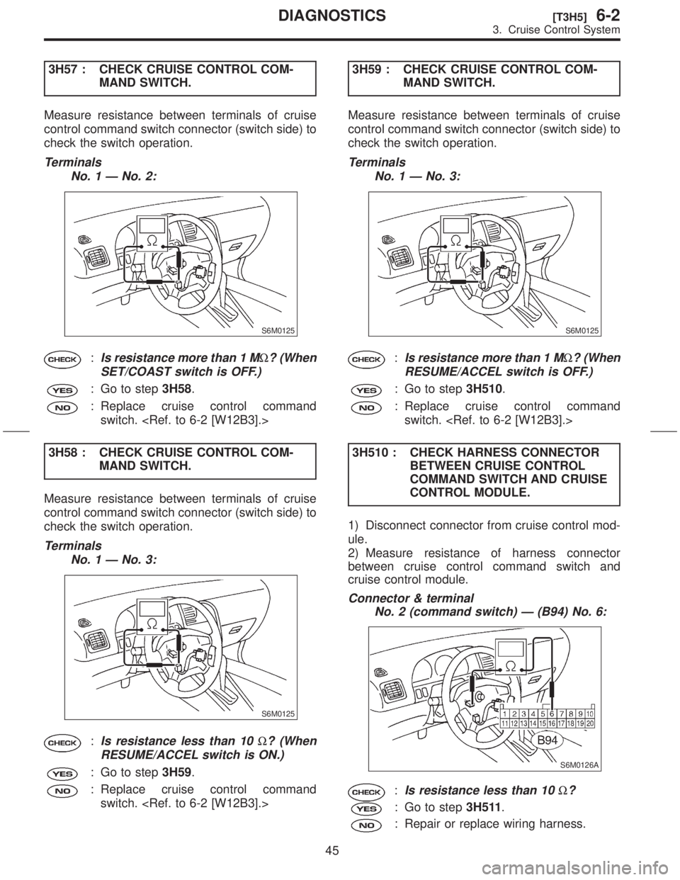
Measure resistance between terminals of cruise
control command switch connector (switch side) to
check the switch operation.
Terminals
No. 1 Ð No. 2:
S6M0125
:Is resistance more than 1 MW? (When
SET/COAST switch is OFF.)
: Go to step3H58.
: Replace cruise control command
switch.
3H58 : CHECK CRUISE CONTROL COM-
MAND SWITCH.
Measure resistance between terminals of cruise
control command switch connector (switch side) to
check the switch operation.
Terminals
No. 1 Ð No. 3:
S6M0125
:Is resistance less than 10W? (When
RESUME/ACCEL switch is ON.)
: Go to step3H59.
: Replace cruise control command
switch. 3H59 : CHECK CRUISE CONTROL COM-
MAND SWITCH.
Measure resistance between terminals of cruise
control command switch connector (switch side) to
check the switch operation.
Terminals
No. 1 Ð No. 3:
S6M0125
:Is resistance more than 1 MW? (When
RESUME/ACCEL switch is OFF.)
: Go to step3H510.
: Replace cruise control command
switch.
3H510 : CHECK HARNESS CONNECTOR
BETWEEN CRUISE CONTROL
COMMAND SWITCH AND CRUISE
CONTROL MODULE.
1) Disconnect connector from cruise control mod-
ule.
2) Measure resistance of harness connector
between cruise control command switch and
cruise control module.
Connector & terminal
No. 2 (command switch) Ð (B94) No. 6:
S6M0126A
:Is resistance less than 10W?
: Go to step3H511.
: Repair or replace wiring harness.
45
[T3H5]6-2DIAGNOSTICS
3. Cruise Control System
Page 108 of 345
3H511 : CHECK HARNESS CONNECTOR
BETWEEN CRUISE CONTROL
COMMAND SWITCH AND CRUISE
CONTROL MODULE.
Measure resistance of harness connector between
cruise control command switch and cruise control
module.
Connector & terminal
No. 3 (command switch) Ð (B94) No. 7:
S6M0127A
:Is resistance less than 10W?
: Replace cruise control module.
6-2 [W12B4].>
: Repair or replace wiring harness.
46
6-2[T3H5]DIAGNOSTICS
3. Cruise Control System
Page 109 of 345
MEMO:
47
[T3H5]6-2DIAGNOSTICS
3. Cruise Control System
Page 110 of 345
6. DIAGNOSTIC CODE 21, 22 AND 23 (VACUUM VALVE, VENT 2 VALVE, VENT 1 VALVE)
DIAGNOSIS:
IOpen or poor contact of vacuum valve, vent 2 valve and vent 1 valve.
TROUBLE SYMPTOM:
ICruise control cannot be set. (Cancels immediately.)
WIRING DIAGRAM:
S6M0128
48
6-2[T3H6]DIAGNOSTICS
3. Cruise Control System
Page 111 of 345
3H61 : MEASURE RESISTANCE OF
VACUUM VALVE, VENT 2 VALVE
AND VENT 1 VALVE.
1) Disconnect connector from actuator.
2) Measure resistance of vacuum valve, vent 2
valve and vent 1 valve.
Terminals
No. 2 Ð No. 3:
S6M0104
:Is resistance less than 22W?
: Go to step3H62.
: Replace actuator.
[W12B1].>
3H62 : MEASURE RESISTANCE OF
VACUUM VALVE, VENT 2 VALVE
AND VENT 1 VALVE.
Measure resistance of vacuum valve, vent 2 valve
and vent 1 valve.
Terminals
No. 2 Ð No. 1:
S6M0104
:Is resistance less than 55W?
: Go to step3H63.
: Replace actuator.
[W12B1].>3H63 : MEASURE RESISTANCE OF
VACUUM VALVE, VENT 2 VALVE
AND VENT 1 VALVE.
Measure resistance of vacuum valve, vent 2 valve
and vent 1 valve.
Terminals
No. 2 Ð No. 4:
S6M0104
:Is resistance less than 55W?
: Go to step3H64.
: Replace actuator.
[W12B1].>
49
[T3H6]6-2DIAGNOSTICS
3. Cruise Control System
Page 112 of 345

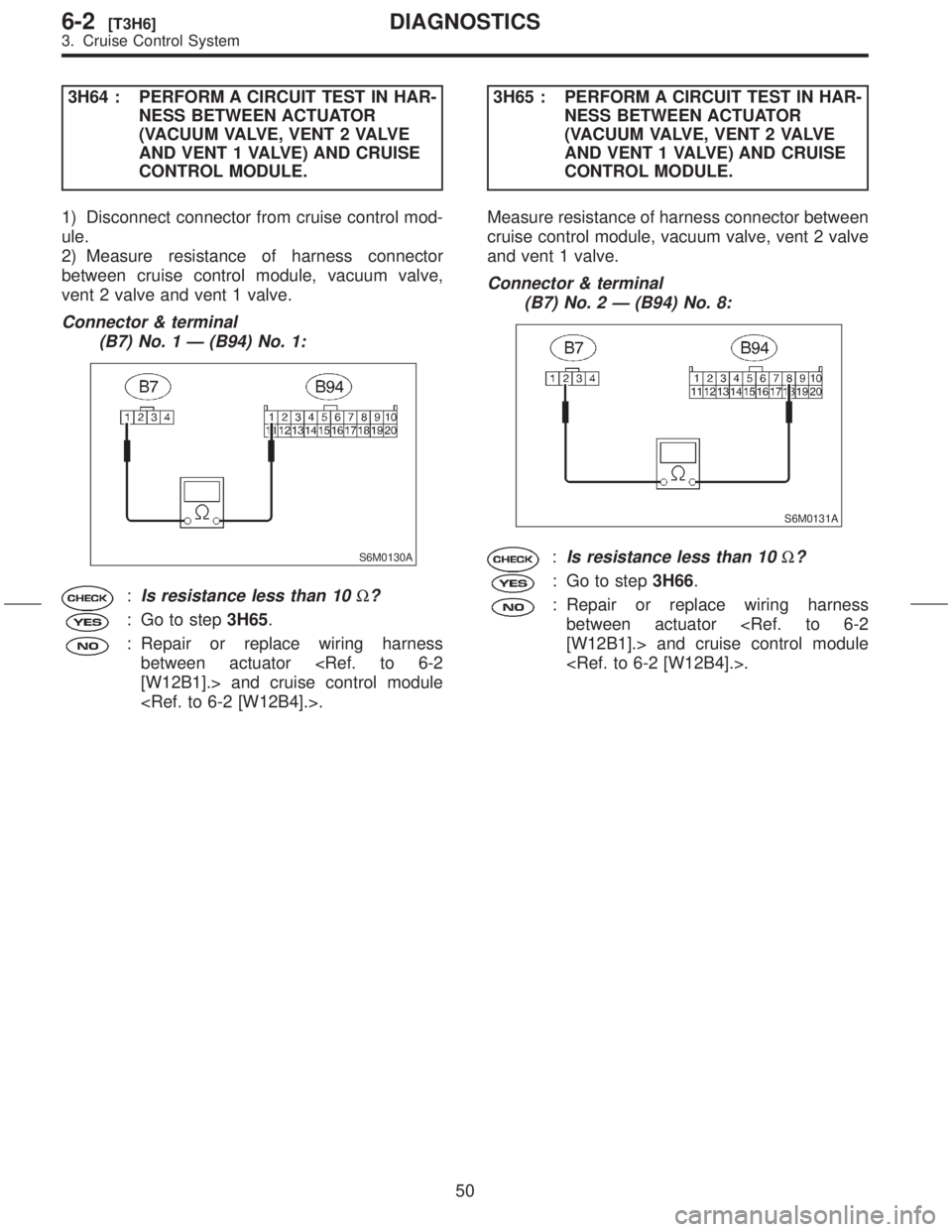
3H64 : PERFORM A CIRCUIT TEST IN HAR-
NESS BETWEEN ACTUATOR
(VACUUM VALVE, VENT 2 VALVE
AND VENT 1 VALVE) AND CRUISE
CONTROL MODULE.
1) Disconnect connector from cruise control mod-
ule.
2) Measure resistance of harness connector
between cruise control module, vacuum valve,
vent 2 valve and vent 1 valve.
Connector & terminal
(B7) No. 1 Ð (B94) No. 1:
S6M0130A
:Is resistance less than 10W?
: Go to step3H65.
: Repair or replace wiring harness
between actuator
[W12B1].> and cruise control module
.3H65 : PERFORM A CIRCUIT TEST IN HAR-
NESS BETWEEN ACTUATOR
(VACUUM VALVE, VENT 2 VALVE
AND VENT 1 VALVE) AND CRUISE
CONTROL MODULE.
Measure resistance of harness connector between
cruise control module, vacuum valve, vent 2 valve
and vent 1 valve.
Connector & terminal
(B7) No. 2 Ð (B94) No. 8:
S6M0131A
:Is resistance less than 10W?
: Go to step3H66.
: Repair or replace wiring harness
between actuator
[W12B1].> and cruise control module
.
50
6-2[T3H6]DIAGNOSTICS
3. Cruise Control System
Page 113 of 345
3H66 : PERFORM A CIRCUIT TEST IN HAR-
NESS BETWEEN ACTUATOR
(VACUUM VALVE, VENT 2 VALVE
AND VENT 1 VALVE) AND CRUISE
CONTROL MODULE.
Measure resistance of harness connector between
cruise control module, vacuum valve, vent 2 valve
and vent 1 valve.
Connector & terminal
(B7) No. 3 Ð (B94) No. 11:
S6M0132A
:Is resistance less than 10W?
: Go to step3H67.
: Repair or replace wiring harness
between actuator
[W12B1].> and cruise control module
.3H67 : PERFORM A CIRCUIT TEST IN HAR-
NESS BETWEEN ACTUATOR
(VACUUM VALVE, VENT 2 VALVE
AND VENT 1 VALVE) AND CRUISE
CONTROL MODULE.
Measure resistance of harness connector between
cruise control module, vacuum valve, vent 2 valve
and vent 1 valve.
Connector & terminal
(B7) No. 4 Ð (B94) No. 2:
S6M0133A
:Is resistance less than 10W?
: Replace cruise control module.
: Repair or replace wiring harness
between actuator
[W12B1].> and cruise control module
.
51
[T3H6]6-2DIAGNOSTICS
3. Cruise Control System
Page 114 of 345

7. DIAGNOSTIC CODE 25 (CRUISE
CONTROL MODULE BUILT-IN RELAY,
CPU RAM)
DIAGNOSIS:
IPoor welding of built-in relay of cruise control
module.
IFailure of built-in CPU RAM of cruise control
module.
TROUBLE SYMPTOM:
ICruise control is canceled and memorized
cruise speed is also canceled.
IOnce cruise control is canceled, cruise control
cannot be set until the ignition switch and cruise
control main switch turns OFF, and then turns ON
again.
NOTE:
Check input/output signal and vehicle speed signal
with select monitor. When signals are in good
condition, failure is in cruise control module.
(Check power supply and ground conditions of
cruise control module.)
I: DIAGNOSTICS CHART WITH
SELECT MONITOR
1. FUNCTION MODE
NOTE:
Select monitor part No.:
Select the ªCruise Controlº system using the select
monitor and set the ªCurrent Data Display & Saveº
mode. The following parameters will then appear
on the display.
IVehicle Speed
The current vehicle speed is shown on the display.
IStop Light Switch
When the brake pedal is depressed, the stop light
switch shown on the display turns from ªOFFº to
ªONº.
IBrake Switch
When the brake pedal is depressed, the brake
switch shown on the display turns from ªOFFº to
ªONº.
IªSET/COASTº Switch
When the cruise control command switch is placed
in the ªSET/COASTº position, the SET/COAST
switch shown on the display turns from ªOFFº to
ªONº.
IªRESUME/ACCELº Switch
When the cruise control command switch is placed
in the ªRESUME/ACCELº position, the RESUME/
ACCEL switch shown on the display turns from
ªOFFº to ªONº.
IClutch/Inhibitor SwitchWhen the clutch pedal is depressed, the clutch/
inhibitor switch shown on the display turns from
ªONº to ªOFFº. (MT)
When the select lever is moved from the ªNº or ªPº
position to any other position, the clutch/inhibitor
switch shown on the display turns from ªONº to
ªOFFº.
52
6-2[T3H7]DIAGNOSTICS
3. Cruise Control System