Page 91 of 345
H: DIAGNOSTICS CHART WITH DIAGNOSTIC CODE
1. DIAGNOSTIC CODE LIST
Diagnostic
codeItem Contents of diagnosis Index No.
11 BRAKE SW/STOP SW Input signals from brake switch ªOFFº, stop light
switch ªONº
(Brake pedal is depressed.)
12 CLUTCH SW/INHIBITOR SW Input signals from clutch switch ªOFFº (MT), or inhibi-
tor switch ªP or Nº (AT)
[Clutch pedal is depressed (MT), or select lever is set
to P or N position (AT).]
13 LOW SPEED LIMIT Low-speed control limiter
14 CANCEL SW Input signal from cancel switch
(faulty SET/COAST switch or RESUME/ACCEL
switch)
21 VACUUM VALVE Faulty vacuum valve or valve drive system
22 VENT 2 VALVE Faulty vent 2 valve or valve drive system
23 VENT 1 VALVE Faulty vent 1 valve or valve drive system
24 SPEED SENSOR Faulty vehicle speed sensor (MT) or transmission
control module (AT)
25 CONTROL MODULE Faulty CPU RAM included in cruise control module
29
[T3H1]6-2DIAGNOSTICS
3. Cruise Control System
Page 92 of 345
2. DIAGNOSTIC CODE 11 (BRAKE SWITCH, STOP LIGHT SWITCH)
DIAGNOSIS:
IFailure or disconnection of the stop light switch and brake switch.
TROUBLE SYMPTOM:
ICruise control cannot be set.
WIRING DIAGRAM:
S6M0112
30
6-2[T3H2]DIAGNOSTICS
3. Cruise Control System
Page 93 of 345

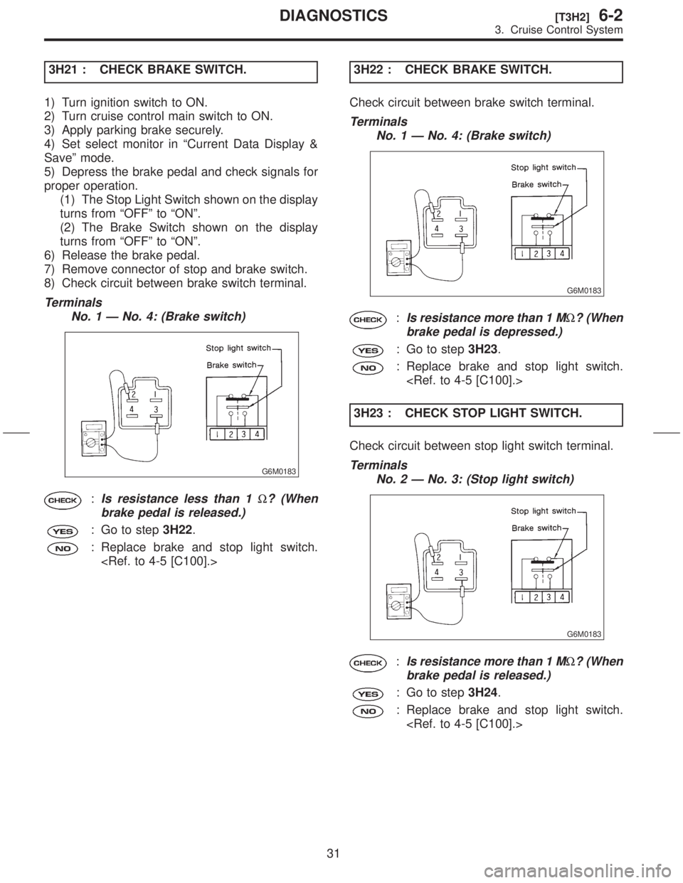
3H21 : CHECK BRAKE SWITCH.
1) Turn ignition switch to ON.
2) Turn cruise control main switch to ON.
3) Apply parking brake securely.
4) Set select monitor in ªCurrent Data Display &
Saveº mode.
5) Depress the brake pedal and check signals for
proper operation.
(1) The Stop Light Switch shown on the display
turns from ªOFFº to ªONº.
(2) The Brake Switch shown on the display
turns from ªOFFº to ªONº.
6) Release the brake pedal.
7) Remove connector of stop and brake switch.
8) Check circuit between brake switch terminal.
Terminals
No. 1 Ð No. 4: (Brake switch)
G6M0183
:Is resistance less than 1W? (When
brake pedal is released.)
: Go to step3H22.
: Replace brake and stop light switch.
3H22 : CHECK BRAKE SWITCH.
Check circuit between brake switch terminal.
Terminals
No. 1 Ð No. 4: (Brake switch)
G6M0183
:Is resistance more than 1 MW? (When
brake pedal is depressed.)
: Go to step3H23.
: Replace brake and stop light switch.
3H23 : CHECK STOP LIGHT SWITCH.
Check circuit between stop light switch terminal.
Terminals
No. 2 Ð No. 3: (Stop light switch)
G6M0183
:Is resistance more than 1 MW? (When
brake pedal is released.)
: Go to step3H24.
: Replace brake and stop light switch.
31
[T3H2]6-2DIAGNOSTICS
3. Cruise Control System
Page 94 of 345
3H24 : CHECK STOP LIGHT SWITCH.
Check circuit between stop light switch terminal.
Terminals
No. 2 Ð No. 3: (Stop light switch)
G6M0183
:Is resistance less than 1W? (When
brake pedal is depressed.)
: Replace cruise control module.
6-2 [W12B4].>
: Replace brake and stop light switch.
32
6-2[T3H2]DIAGNOSTICS
3. Cruise Control System
Page 95 of 345
MEMO:
33
[T3H2]6-2DIAGNOSTICS
3. Cruise Control System
Page 96 of 345
3. DIAGNOSTIC CODE 12 (CLUTCH SWITCH, INHIBITOR SWITCH)
DIAGNOSIS:
IFailure or disconnection of the clutch switch. (MT)
IFailure or disconnection of the inhibitor switch. (AT)
TROUBLE SYMPTOM:
ICruise control cannot be set.
WIRING DIAGRAM:
S6M0384
34
6-2[T3H3]DIAGNOSTICS
3. Cruise Control System
Page 97 of 345
3H31 : CHECK CLUTCH SWITCH. (MT)
1) Turn ignition switch to ON.
2) Turn cruise control main switch to ON.
3) Apply parking brake securely.
4) Set select monitor in ªCurrent Data Display &
Saveº mode.
5) Depress the clutch pedal and check signal for
proper operation. (MT)
The Clutch/Inhibitor Switch shown on the display
turns from ªONº to ªOFFº.
6) Disconnect connector of clutch switch.
7) Check continuity of the clutch switch.
Terminals
No. 1 Ð No. 2:
G6M0184
:Is resistance less than 10W? (When
clutch pedal is released.)
: Go to step3H32.
: Replace clutch switch.
[C100].>3H32 : CHECK CLUTCH SWITCH. (MT)
Check continuity of the clutch switch.
Terminals
No. 1 Ð No. 2:
G6M0184
:Is resistance more than 1 MW? (When
clutch pedal is depressed.)
: Replace cruise control module.
6-2 [W12B4].>
: Replace clutch switch.
[C100].>
35
[T3H3]6-2DIAGNOSTICS
3. Cruise Control System
Page 98 of 345

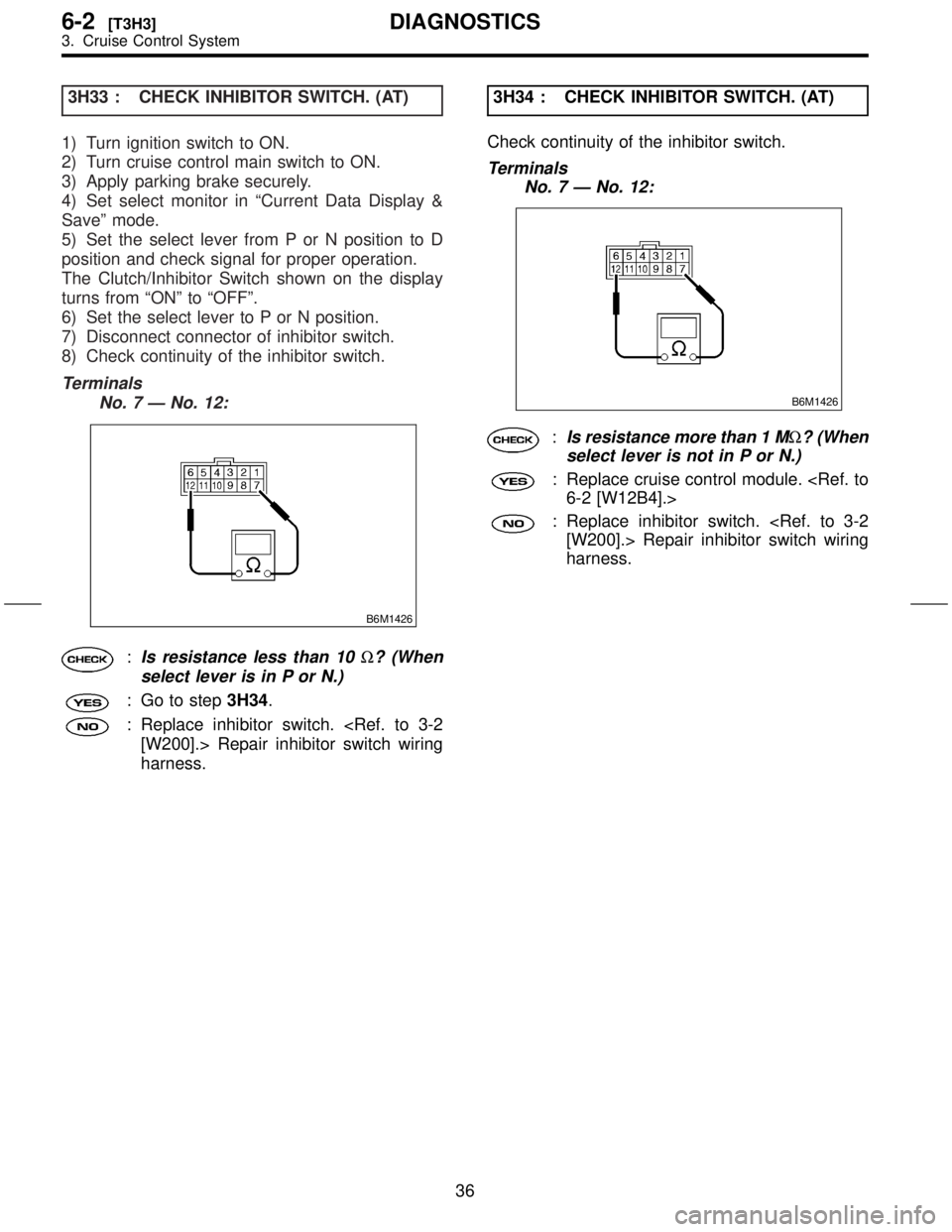
3H33 : CHECK INHIBITOR SWITCH. (AT)
1) Turn ignition switch to ON.
2) Turn cruise control main switch to ON.
3) Apply parking brake securely.
4) Set select monitor in ªCurrent Data Display &
Saveº mode.
5) Set the select lever from P or N position to D
position and check signal for proper operation.
The Clutch/Inhibitor Switch shown on the display
turns from ªONº to ªOFFº.
6) Set the select lever to P or N position.
7) Disconnect connector of inhibitor switch.
8) Check continuity of the inhibitor switch.
Terminals
No. 7 Ð No. 12:
B6M1426
:Is resistance less than 10W? (When
select lever is in P or N.)
: Go to step3H34.
: Replace inhibitor switch.
[W200].> Repair inhibitor switch wiring
harness.3H34 : CHECK INHIBITOR SWITCH. (AT)
Check continuity of the inhibitor switch.
Terminals
No. 7 Ð No. 12:
B6M1426
:Is resistance more than 1 MW? (When
select lever is not in P or N.)
: Replace cruise control module.
6-2 [W12B4].>
: Replace inhibitor switch.
[W200].> Repair inhibitor switch wiring
harness.
36
6-2[T3H3]DIAGNOSTICS
3. Cruise Control System