1999 NISSAN PRIMERA stop start
[x] Cancel search: stop startPage 323 of 2267
![NISSAN PRIMERA 1999 Electronic Repair Manual SELF-DIAGNOSTIC MODE
Regarding items detected in ªSELF-DIAG RESULTSº mode, refer to ªDiagnostic Trouble chartº.
DATA MONITOR MODE
Monitored item
[Unit]ECM
input
signalsMain
signalsDescription Rema](/manual-img/5/57377/w960_57377-322.png "NISSAN PRIMERA 1999 Electronic Repair Manual SELF-DIAGNOSTIC MODE
Regarding items detected in ªSELF-DIAG RESULTSº mode, refer to ªDiagnostic Trouble chartº.
DATA MONITOR MODE
Monitored item
[Unit]ECM
input
signalsMain
signalsDescription Rema")
SELF-DIAGNOSTIC MODE
Regarding items detected in ªSELF-DIAG RESULTSº mode, refer to ªDiagnostic Trouble chartº.
DATA MONITOR MODE
Monitored item
[Unit]ECM
input
signalsMain
signalsDescription Remarks
CKPS×RPM
(TDC) [rpm]
qq
lThe engine speed computed from the
crankshaft position sensor (TDC) sig-
nal is displayed.
CMPS×RPM -
PUMP [rpm]
qq
lThe engine speed computed from the
camshaft position sensor (PUMP) sig-
nal is displayed.
COOLAN TEMP/S
[ÉC] or [ÉF]
qq
lThe engine coolant temperature (deter-
mined by the signal voltage of the
engine coolant temperature sensor) is
displayed.lWhen the engine coolant temperature
sensor is open or short-circuited, ECM
enters fail-safe mode. The engine cool-
ant temperature determined by the
ECM is displayed.
VHCL SPEED SE
[km/h] or [mph]
qq
lThe vehicle speed computed from the
vehicle speed sensor signal or ABS
actuator and electric unit (control unit)
signal is displayed.
FUEL TEMP SEN
[ÉC] or [ÉF]
qq
lThe fuel temperature (determined by
the signal voltage of the fuel tempera-
ture sensor) is displayed.
ACCEL POS SEN
[V]
qqlThe accelerator position sensor signal
voltage is displayed.
OFF ACCEL POS
[ON/OFF]
qqlIndicates [ON/OFF] condition from the
accelerator position switch signal.
C/SLEEV POS/S [V]
qqlThe control sleeve position sensor sig-
nal voltage is displayed.
BATTERY VOLT [V]
qqlThe power supply voltage of ECM is
displayed.
START SIGNAL
[ON/OFF]
qqlIndicates [ON/OFF] condition from the
starter signal.lAfter starting the engine, [OFF] is dis-
played regardless of the starter signal.
AIR COND SIG
[ON/OFF]
qq
lIndicates [ON/OFF] condition of the air
conditioner switch as determined by
the air conditioner signal.
BRAKE SW
[ON/OFF]
qlIndicates [ON/OFF] condition of the
stio lamp switch.
BRAKE SW2
[ON/OFF]
qlIndicates [ON/OFF] condition of the
stio lamp switch 2.
IGN SW
[ON/OFF]
qqlIndicates [ON/OFF] condition from igni-
tion switch.
MAS AIR/FL SE [V]
qqlThe signal voltage of the mass air flow
sensor is displayed.lWhen the engine is stopped, a certain
value is indicated.
ACT INJ TIMG [É]
q
lThe actual injection timing angle deter-
mined by the ECM (an approximate
average angle between injection start
and end from TDC) is displayed.
TARGET F/INJ
[mm
3/STROKE]q
lThe target fuel injection quantity
(determined by the ECM according to
the input signal) is indicated.
NOTE:
Any monitored item that does not match the vehicle being diagnosed is deleted from the display automatically.
ON BOARD DIAGNOSTIC SYSTEM DESCRIPTIONCD20T
CONSULT-II (Cont'd)
EC-29
Page 328 of 2267
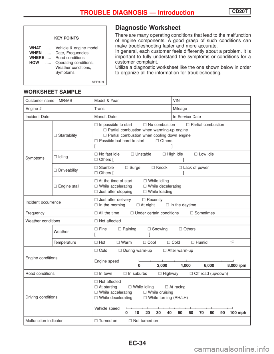
Diagnostic Worksheet
There are many operating conditions that lead to the malfunction
of engine components. A good grasp of such conditions can
make troubleshooting faster and more accurate.
In general, each customer feels differently about a problem. It is
important to fully understand the symptoms or conditions for a
customer complaint.
Utilize a diagnostic worksheet like the one shown below in order
to organize all the information for troubleshooting.
WORKSHEET SAMPLE
Customer name MR/MS Model & Year VIN
Engine # Trans. Mileage
Incident Date Manuf. Date In Service Date
SymptomslStartabilitylImpossible to startlNo combustionlPartial combustion
lPartial combustion when warming-up engine
lPartial combustion when cooling down engine
lPossible but hard to startlOthers
[]
lIdlinglNo fast idlelUnstablelHigh idlelLow idle
lOthers [ ]
lDriveabilitylStumblelSurgelKnocklLack of power
lOthers [ ]
lEngine stalllAt the time of startlWhile idling
lWhile acceleratinglWhile decelerating
lJust after stoppinglWhile loading
Incident occurrencelJust after deliverylRecently
lIn the morninglAt nightlIn the daytime
FrequencylAll the timelUnder certain conditionslSometimes
Weather conditionslNot affected
WeatherlFinelRaininglSnowinglOthers
[]
TemperaturelHotlWarmlCoollColdlHumid ÉF
Engine conditionslColdlDuring warm-uplAfter warm-up
Engine speed
0 2,000 4,000 6,000 8,000 rpm
Road conditionslIn townlIn suburbslHighwaylOff road (up/down)
Driving conditionslNot affected
lAt startinglWhile idlinglAt racing
lWhile acceleratinglWhile cruising
lWhile deceleratinglWhile turning (RH/LH)
Vehicle speed
0 102030405060708090100mph
Malfunction indicatorlTurned onlNot turned on
SEF907L
KEY POINTS
WHAT..... Vehicle & engine model
WHEN..... Date, Frequencies
WHERE..... Road conditions
HOW..... Operating conditions,
Weather conditions,
Symptoms
TROUBLE DIAGNOSIS Ð IntroductionCD20T
EC-34
Page 332 of 2267
pA
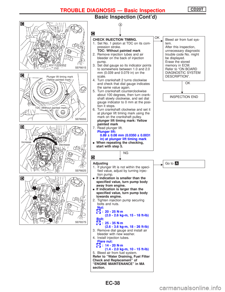
CHECK INJECTION TIMING.
1. Set No. 1 piston at TDC on its com-
pression stroke.
TDC: Without painted mark
2. Remove injection tubes and air
bleeder on the back of injection
pump.
3. Set dial gauge so its indicator points
to somewhere between 1.0 and 2.0
mm (0.039 and 0.079 in) on the
scale.
4. Turn crankshaft 2 turns clockwise
and check that dial gauge indicates
the same value again.
5. Turn crankshaft counterclockwise
about 100 degrees, then turn crank-
shaft slowly clockwise, and set dial
gauge indicator to 0 mm at the posi-
tion it stops.
6. Turn crankshaft clockwise and set it
at plunger lift timing mark using the
mark on the crankshaft pulley.
plunger lift timing mark: Yellow
painted mark
7. Read plunger lift.
Plunger lift:
0.89 0.08 mm (0.0350 0.0031
in) at plunger lift timing mark
lWhen repeating the checking,
start with step 5.
NG
EOK
Bleed air from fuel sys-
tem.
After this inspection,
unnecessary diagnostic
trouble code No. might
be displayed.
Erase the stored
memory in ECM.
Refer to ªON BOARD
DIAGNOSTIC SYSTEM
DESCRIPTIONº.
OK
INSPECTION END
Adjusting
1. If plunger lift is not within the speci-
fied value, adjust by turning injec-
tion pump.
lIf indication is smaller than the
specified value, turn pump body
away from engine.
lIf indication is larger than the
specified value, turn pump body
towards engine.
2. Tighten injection pump securing
bolts and nuts.
Nut:
: 20-25N´m
(2.0 - 2.6 kg-m, 15 - 18 ft-lb)
Bolt:
: 25-35N´m
(2.6 - 3.6 kg-m, 18 - 26 ft-lb)
3. Remove dial gauge and install air
bleeder with new washer.
4. Install injection tubes.
Flare nut:
: 14-20N´m
(1.4 - 2.0 kg-m, 10 - 15 ft-lb)
5. Bleed air from fuel system.
Refer to ªWater Draining, Fuel Filter
Check and Replacementº of
ªENGINE MAINTENANCEº in MA
section.
EGo to
SEF661S
SEF655S
Plunger lift timing mark
(Yellow painted mark)
TDC (Without painted mark)
SEF662S
Increase
Decrease
SEF657S
H
H
H
TROUBLE DIAGNOSIS Ð Basic InspectionCD20T
Basic Inspection (Cont'd)
EC-38
Page 343 of 2267
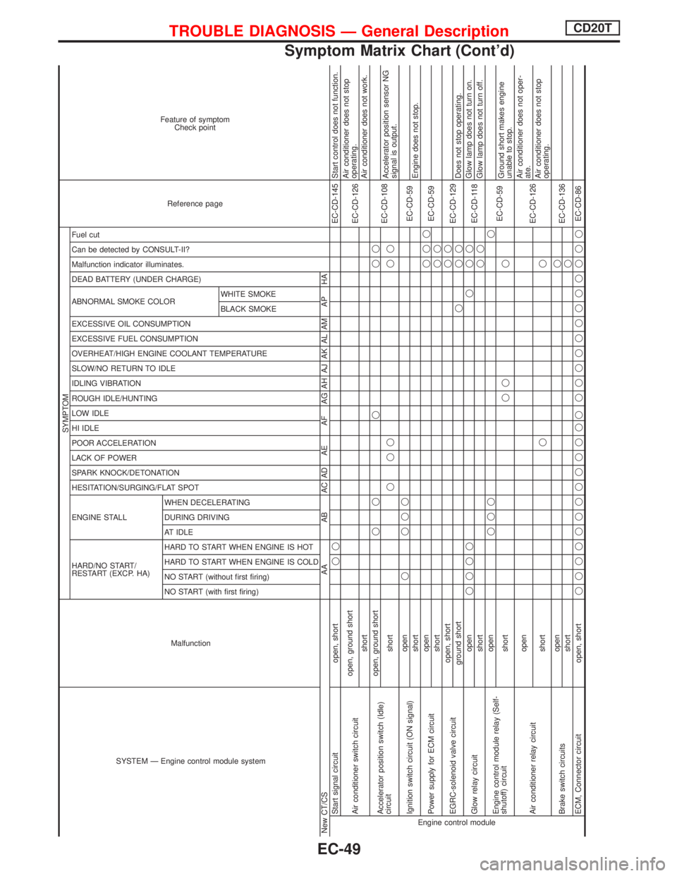
SYSTEM Ð Engine control module systemMalfunction
SYMPTOM
Reference page Feature of symptom
Check point
HARD/NO START/
RESTART (EXCP. HA) ENGINE STALL HESITATION/SURGING/FLAT SPOT SPARK KNOCK/DETONATION
LACK OF POWER
POOR ACCELERATION
HI IDLE
LOW IDLE
ROUGH IDLE/HUNTING
IDLING VIBRATION
SLOW/NO RETURN TO IDLE
OVERHEAT/HIGH ENGINE COOLANT TEMPERATURE
EXCESSIVE FUEL CONSUMPTION
EXCESSIVE OIL CONSUMPTION ABNORMAL SMOKE COLOR
DEAD BATTERY (UNDER CHARGE) Malfunction indicator illuminates.
Can be detected by CONSULT-II?
Fuel cut
NO START (with first firing) NO START (without first firing)
HARD TO START WHEN ENGINE IS COLD
HARD TO START WHEN ENGINE IS HOT
AT IDLE
DURING DRIVING
WHEN DECELERATINGBLACK SMOKE WHITE SMOKE
New CT/CS AA AB AC AD AE AF AG AH AJ AK AL AM AP HAEngine control moduleStart signal circuit open, shortqqEC-CD-145 Start control does not function.
Air conditioner switch circuitopen, ground short
EC-CD-126Air conditioner does not stop
operating.
shortAir conditioner does not work.
Accelerator position switch (Idle)
circuitopen, ground shortqq q qq
EC-CD-108
shortqqq qqAccelerator position sensor NG
signal is output.
Ignition switch circuit (ON signal)openq qqq
EC-CD-59
shortEngine does not stop.
Power supply for ECM circuitopenqqq
EC-CD-59
shortqq
EGRC-solenoid valve circuitopen, shortqq
EC-CD-129
ground shortqqqDoes not stop operating.
Glow relay circuitopenqqqq q qq
EC-CD-118Glow lamp does not turn on.
shortqqGlow lamp does not turn off.
Engine control module relay (Self-
shutoff) circuitopenqqqq
EC-CD-59
shortqq qGround short makes engine
unable to stop.
Air conditioner relay circuitopen
EC-CD-126Air conditioner does not oper-
ate.
shortqqAir conditioner does not stop
operating.
Brake switch circuitsopenq
EC-CD-136
shortq
ECM, Connector circuit open, shortqqqqqqqqqqqqq qqqqqqqqqqqqEC-CD-86
TROUBLE DIAGNOSIS Ð General DescriptionCD20T
Symptom Matrix Chart (Cont'd)
EC-49
Page 344 of 2267
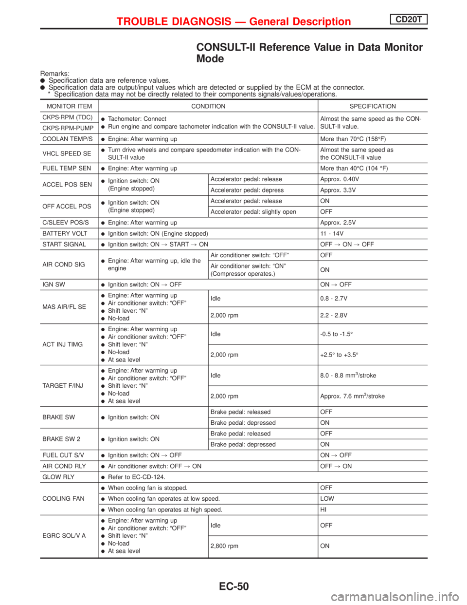
CONSULT-II Reference Value in Data Monitor
Mode
Remarks:lSpecification data are reference values.lSpecification data are output/input values which are detected or supplied by the ECM at the connector.
* Specification data may not be directly related to their components signals/values/operations.
MONITOR ITEM CONDITION SPECIFICATION
CKPS×RPM (TDC)
lTachometer: ConnectlRun engine and compare tachometer indication with the CONSULT-II value.Almost the same speed as the CON-
SULT-II value.
CKPS×RPM-PUMP
COOLAN TEMP/S
lEngine: After warming up More than 70ÉC (158ÉF)
VHCL SPEED SE
lTurn drive wheels and compare speedometer indication with the CON-
SULT-II valueAlmost the same speed as
the CONSULT-II value
FUEL TEMP SEN
lEngine: After warming up More than 40ÉC (104 ÉF)
ACCEL POS SEN
lIgnition switch: ON
(Engine stopped)Accelerator pedal: release Approx. 0.40V
Accelerator pedal: depress Approx. 3.3V
OFF ACCEL POS
lIgnition switch: ON
(Engine stopped)Accelerator pedal: release ON
Accelerator pedal: slightly open OFF
C/SLEEV POS/S
lEngine: After warming up Approx. 2.5V
BATTERY VOLT
lIgnition switch: ON (Engine stopped) 11 - 14V
START SIGNAL
lIgnition switch: ON,START,ON OFF,ON,OFF
AIR COND SIG
lEngine: After warming up, idle the
engineAir conditioner switch: ªOFFº OFF
Air conditioner switch: ªONº
(Compressor operates.)ON
IGN SW
lIgnition switch: ON,OFF ON,OFF
MAS AIR/FL SE
lEngine: After warming uplAir conditioner switch: ªOFFºlShift lever: ªNºlNo-loadIdle 0.8 - 2.7V
2,000 rpm 2.2 - 2.8V
ACT INJ TIMG
lEngine: After warming uplAir conditioner switch: ªOFFºlShift lever: ªNºlNo-loadlAt sea levelIdle -0.5 to -1.5É
2,000 rpm +2.5É to +3.5É
TARGET F/INJ
lEngine: After warming uplAir conditioner switch: ªOFFºlShift lever: ªNºlNo-loadlAt sea levelIdle 8.0 - 8.8 mm
3/stroke
2,000 rpm Approx. 7.6 mm
3/stroke
BRAKE SW
lIgnition switch: ONBrake pedal: released OFF
Brake pedal: depressed ON
BRAKE SW 2
lIgnition switch: ONBrake pedal: released OFF
Brake pedal: depressed ON
FUEL CUT S/V
lIgnition switch: ON,OFF ON,OFF
AIR COND RLY
lAir conditioner switch: OFF,ON OFF,ON
GLOW RLY
lRefer to EC-CD-124.
COOLING FAN
lWhen cooling fan is stopped. OFF
lWhen cooling fan operates at low speed. LOW
lWhen cooling fan operates at high speed. HI
EGRC SOL/V A
lEngine: After warming uplAir conditioner switch: ªOFFºlShift lever: ªNºlNo-loadlAt sea levelIdle OFF
2,800 rpm ON
TROUBLE DIAGNOSIS Ð General DescriptionCD20T
EC-50
Page 354 of 2267
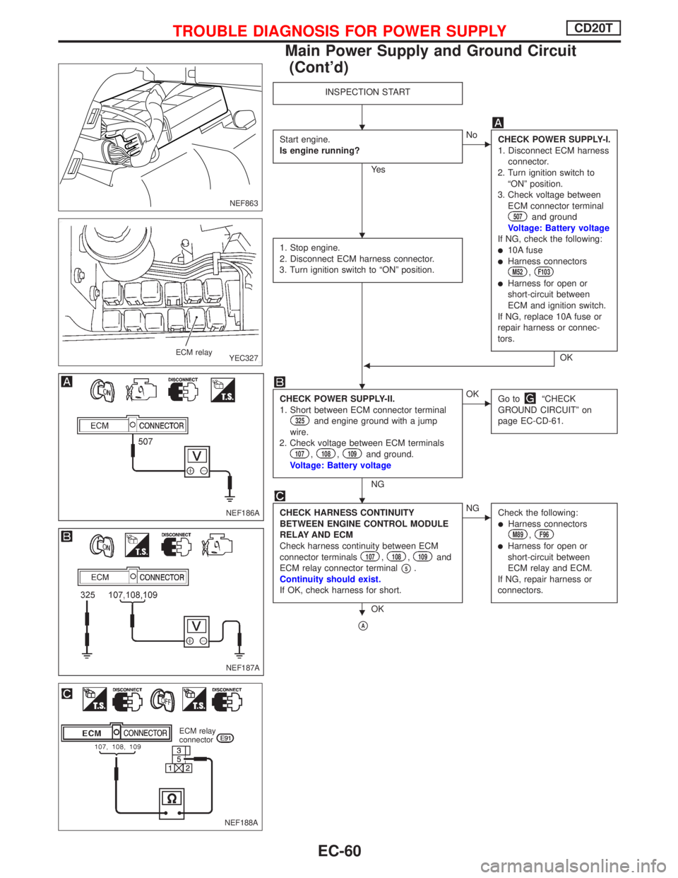
INSPECTION START
Start engine.
Is engine running?
Ye s
ENo
CHECK POWER SUPPLY-I.
1. Disconnect ECM harness
connector.
2. Turn ignition switch to
ªONº position.
3. Check voltage between
ECM connector terminal
507and ground
Voltage: Battery voltage
If NG, check the following:
l10A fuselHarness connectorsM52,F103
lHarness for open or
short-circuit between
ECM and ignition switch.
If NG, replace 10A fuse or
repair harness or connec-
tors.
OK 1. Stop engine.
2. Disconnect ECM harness connector.
3. Turn ignition switch to ªONº position.F
CHECK POWER SUPPLY-II.
1. Short between ECM connector terminal
325and engine ground with a jump
wire.
2. Check voltage between ECM terminals
107,108,109and ground.
Voltage: Battery voltage
NG
EOK
Go toªCHECK
GROUND CIRCUITº on
page EC-CD-61.
CHECK HARNESS CONTINUITY
BETWEEN ENGINE CONTROL MODULE
RELAY AND ECM
Check harness continuity between ECM
connector terminals
107,108,109and
ECM relay connector terminal
p5.
Continuity should exist.
If OK, check harness for short.
OK
ENG
Check the following:
lHarness connectorsM89,F96
lHarness for open or
short-circuit between
ECM relay and ECM.
If NG, repair harness or
connectors.
pA
NEF863
YEC327 ECM relay
NEF186A
NEF187A
NEF188A
ECM relay
connector
H
H
H
H
H
TROUBLE DIAGNOSIS FOR POWER SUPPLYCD20T
Main Power Supply and Ground Circuit
(Cont'd)
EC-60
Page 359 of 2267
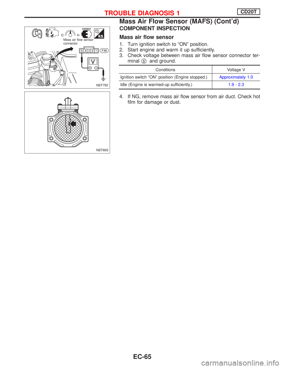
COMPONENT INSPECTION
Mass air flow sensor
1. Turn ignition switch to ªONº position.
2. Start engine and warm it up sufficiently.
3. Check voltage between mass air flow sensor connector ter-
minal
p5and ground.
Conditions Voltage V
Ignition switch ªONº position (Engine stopped.)Approximately 1.0
Idle (Engine is warmed-up sufficiently.)1.9 - 2.3
4. If NG, remove mass air flow sensor from air duct. Check hot
film for damage or dust.
NEF792 Mass air flow sensor
connector
NEF669
TROUBLE DIAGNOSIS 1CD20T
Mass Air Flow Sensor (MAFS) (Cont'd)
EC-65
Page 464 of 2267
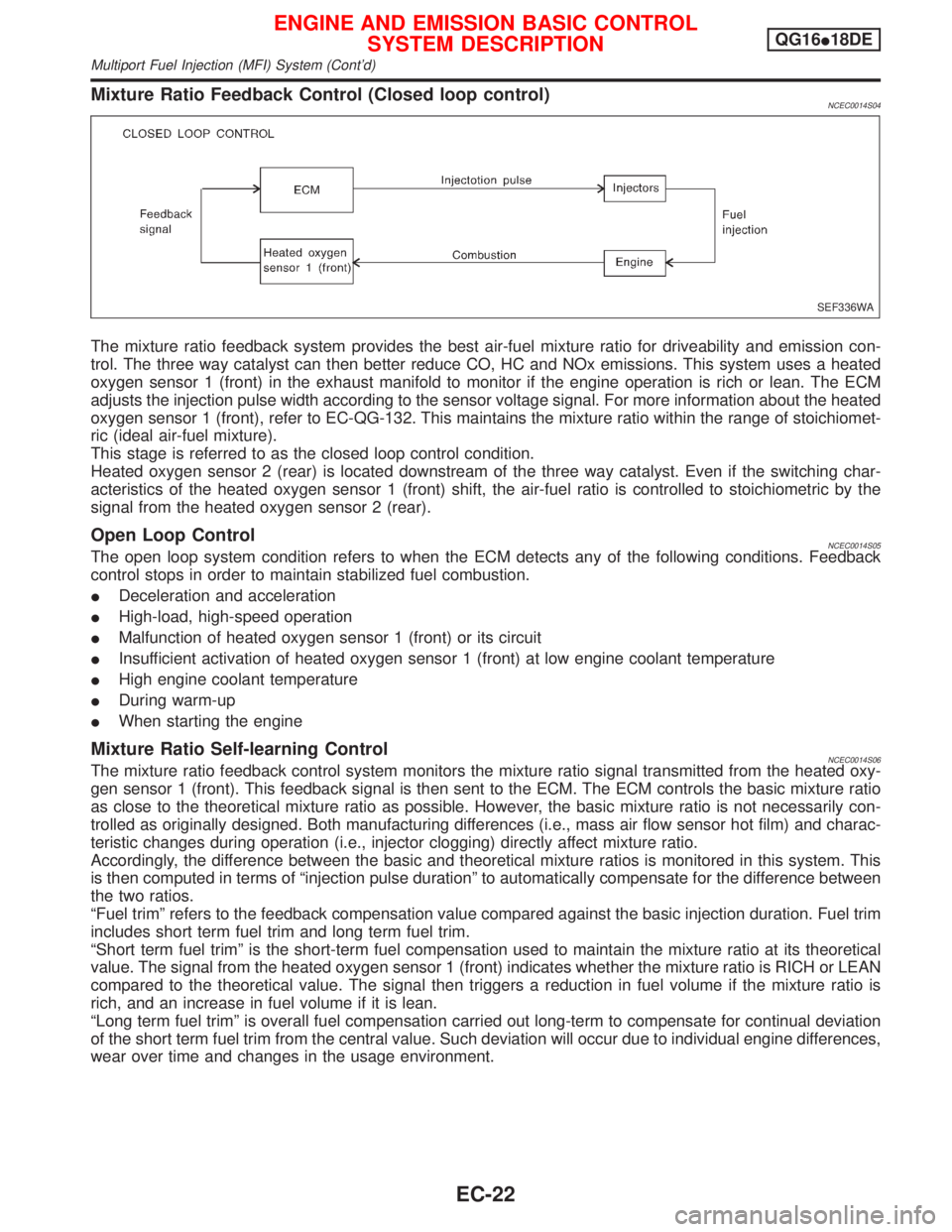
Mixture Ratio Feedback Control (Closed loop control)NCEC0014S04
The mixture ratio feedback system provides the best air-fuel mixture ratio for driveability and emission con-
trol. The three way catalyst can then better reduce CO, HC and NOx emissions. This system uses a heated
oxygen sensor 1 (front) in the exhaust manifold to monitor if the engine operation is rich or lean. The ECM
adjusts the injection pulse width according to the sensor voltage signal. For more information about the heated
oxygen sensor 1 (front), refer to EC-QG-132. This maintains the mixture ratio within the range of stoichiomet-
ric (ideal air-fuel mixture).
This stage is referred to as the closed loop control condition.
Heated oxygen sensor 2 (rear) is located downstream of the three way catalyst. Even if the switching char-
acteristics of the heated oxygen sensor 1 (front) shift, the air-fuel ratio is controlled to stoichiometric by the
signal from the heated oxygen sensor 2 (rear).
Open Loop ControlNCEC0014S05The open loop system condition refers to when the ECM detects any of the following conditions. Feedback
control stops in order to maintain stabilized fuel combustion.
IDeceleration and acceleration
IHigh-load, high-speed operation
IMalfunction of heated oxygen sensor 1 (front) or its circuit
IInsufficient activation of heated oxygen sensor 1 (front) at low engine coolant temperature
IHigh engine coolant temperature
IDuring warm-up
IWhen starting the engine
Mixture Ratio Self-learning ControlNCEC0014S06The mixture ratio feedback control system monitors the mixture ratio signal transmitted from the heated oxy-
gen sensor 1 (front). This feedback signal is then sent to the ECM. The ECM controls the basic mixture ratio
as close to the theoretical mixture ratio as possible. However, the basic mixture ratio is not necessarily con-
trolled as originally designed. Both manufacturing differences (i.e., mass air flow sensor hot film) and charac-
teristic changes during operation (i.e., injector clogging) directly affect mixture ratio.
Accordingly, the difference between the basic and theoretical mixture ratios is monitored in this system. This
is then computed in terms of ªinjection pulse durationº to automatically compensate for the difference between
the two ratios.
ªFuel trimº refers to the feedback compensation value compared against the basic injection duration. Fuel trim
includes short term fuel trim and long term fuel trim.
ªShort term fuel trimº is the short-term fuel compensation used to maintain the mixture ratio at its theoretical
value. The signal from the heated oxygen sensor 1 (front) indicates whether the mixture ratio is RICH or LEAN
compared to the theoretical value. The signal then triggers a reduction in fuel volume if the mixture ratio is
rich, and an increase in fuel volume if it is lean.
ªLong term fuel trimº is overall fuel compensation carried out long-term to compensate for continual deviation
of the short term fuel trim from the central value. Such deviation will occur due to individual engine differences,
wear over time and changes in the usage environment.
SEF336WA
ENGINE AND EMISSION BASIC CONTROL
SYSTEM DESCRIPTIONQG16I18DE
Multiport Fuel Injection (MFI) System (Cont'd)
EC-22