Page 91 of 558

ENGINE – Piston and Connecting Rod11-66
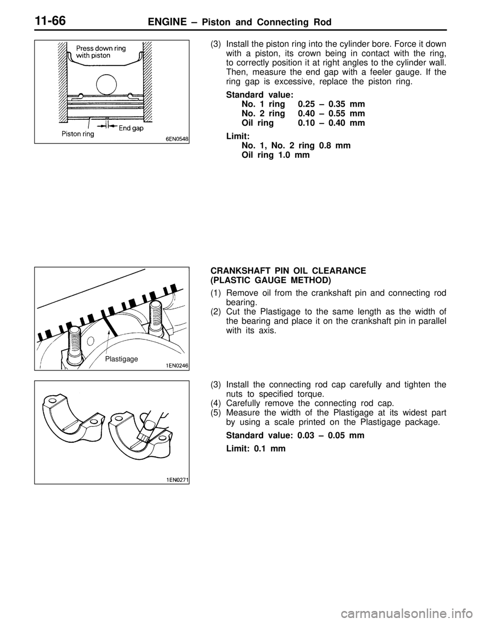
(3) Install the piston ring into the cylinder bore. Force it down
with a piston, its crown being in contact with the ring,
to correctly position it at right angles to the cylinder wall.
Then, measure the end gap with a feeler gauge. If the
ring gap is excessive, replace the piston ring.
Standard value:
No. 1 ring 0.25 – 0.35 mm
No. 2 ring 0.40 – 0.55 mm
Oil ring 0.10 – 0.40 mm
Limit:
No. 1, No. 2 ring 0.8 mm
Oil ring 1.0 mm
CRANKSHAFT PIN OIL CLEARANCE
(PLASTIC GAUGE METHOD)
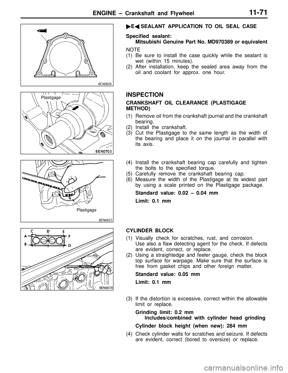
(1) Remove oil from the crankshaft pin and connecting rod
bearing.
(2) Cut the Plastigage to the same length as the width of
the bearing and place it on the crankshaft pin in parallel
with its axis.
(3) Install the connecting rod cap carefully and tighten the
nuts to specified torque.
(4) Carefully remove the connecting rod cap.
(5) Measure the width of the Plastigage at its widest part
by using a scale printed on the Plastigage package.
Standard value: 0.03 – 0.05 mm
Limit: 0.1 mm
Plastigage
Page 96 of 558

ENGINE – Crankshaft and Flywheel11-71
�E�SEALANT APPLICATION TO OIL SEAL CASE
Specified sealant:
Mitsubishi Genuine Part No. MD970389 or equivalent
NOTE
(1) Be sure to install the case quickly while the sealant is
wet (within 15 minutes).
(2) After installation, keep the sealed area away from the
oil and coolant for approx. one hour.
INSPECTION
CRANKSHAFT OIL CLEARANCE (PLASTIGAGE
METHOD)
(1) Remove oil from the crankshaft journal and the crankshaft
bearing.
(2) Install the crankshaft.
(3) Cut the Plastigage to the same length as the width of
the bearing and place it on the journal in parallel with
its axis.
(4) Install the crankshaft bearing cap carefully and tighten
the bolts to the specified torque.
(5) Carefully remove the crankshaft bearing cap.
(6) Measure the width of the Plastigage at its widest part
by using a scale printed on the Plastigage package.
Standard value: 0.02 – 0.04 mm
Limit: 0.1 mm
CYLINDER BLOCK
(1) Visually check for scratches, rust, and corrosion.
Use also a flaw detecting agent for the check. If defects
are evident, correct, or replace.
(2) Using a straightedge and feeler gauge, check the block
top surface for warpage. Make sure that the surface is
free from gasket chips and other foreign matter.
Standard value: 0.05 mm
Limit: 0.1 mm
(3) If the distortion is excessive, correct within the allowable
limit or replace.
Grinding limit: 0.2 mm
Includes/combined with cylinder head grinding
Cylinder block height (when new): 284 mm
(4) Check cylinder walls for scratches and seizure. If defects
are evident, correct (bored to oversize) or replace.
Plastigage
Plastigage
Page 102 of 558

ENGINE – Turbocharger11-77
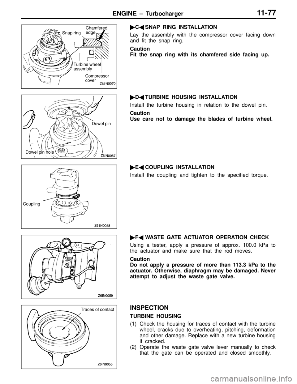
�C�SNAP RING INSTALLATION
Lay the assembly with the compressor cover facing down
and fit the snap ring.
Caution
Fit the snap ring with its chamfered side facing up.
�D�TURBINE HOUSING INSTALLATION
Install the turbine housing in relation to the dowel pin.
Caution
Use care not to damage the blades of turbine wheel.
�E�COUPLING INSTALLATION
Install the coupling and tighten to the specified torque.
�F�WASTE GATE ACTUATOR OPERATION CHECK
Using a tester, apply a pressure of approx. 100.0 kPa to
the actuator and make sure that the rod moves.
Caution
Do not apply a pressure of more than 113.3 kPa to the
actuator. Otherwise, diaphragm may be damaged. Never
attempt to adjust the waste gate valve.
INSPECTION
TURBINE HOUSING
(1) Check the housing for traces of contact with the turbine
wheel, cracks due to overheating, pitching, deformation
and other damage. Replace with a new turbine housing
if cracked.
(2) Operate the waste gate valve lever manually to check
that the gate can be operated and closed smoothly.
Compressor
cover
Turbine wheel
assembly
Chamfered
edge
Snap ring
Dowel pin
Dowel pin hole
Coupling
Traces of contact
Page 196 of 558
FRONT AXLE – Axle Hub and Knuckle 26-2
INSPECTION
LOWER ARM BALL JOINT ROTATION STARTING
TORQUE CHECK
(1) After shaking the ball joint stud several times, install the
nut to the stud and use the special tool to measure the
rotation starting torque of the ball joint.
Standard value: 1.0 – 3.4 Nm
(2) When the measured value exceeds the standard value,
replace the ball joint assembly.
(3) When the measured value is lower than the standard
value, check that the ball joint turns smoothly without
excessive play. If so, it is possible to use that ball joint.
LOWER ARM BALL JOINT DUST COVER
REPLACEMENT
When the dust cover is damaged during service work or grease
leaks out from the dust cover, replace the dust cover in the
conventional procedure. After replacement, check the dust
cover for cracks or damage by pushing it with finger.
MB990326
Page 198 of 558
REAR AXLE – General / Service Specifications / Lubricant27-2
GENERAL
OUTLINE OF CHANGE
�The descriptions of the service procedures for the AYC system including the troubleshooting using
an MUT-II tester has been incorporated.
SERVICE SPECIFICATIONS
ItemsStandard valueLimit
Rear axle total backlash mm–5
Pressure generated by hydraulic unit MPa0 – 1.6–
Wheel bearing axial play mm–0.05
Wheel bearing rotation starting torque Nm–1.0 or less
LUBRICANT
ItemsSpecified lubricantCapacity
Gear oilTorque
transfer
differential
DifferentialHypoid gear oil API classification GL-5 or higher
SAE viscosity No. 90, 80W0.41 ± 0.02 �
differentialTorque transfer
mechanismMITSUBISHI GENUINE DIA QUEEN AYC FLUID0.70�0
�0.05�
Hydraulic piping fluidDia Queen ATF SPII or equivalent1 �
Torque transfer mechanism oil seal lipsVaselineAs required
Page 199 of 558
REAR AXLE – Special Tools27-3
SPECIAL TOOLS
ToolNumberNameUse
MB991502MUT-II sub-
assemblyInspection of AYC
(diagnosis display by MUT-II)
MB991529Diagnosis code
check harnessInspection of AYC
(diagnosis display by AYC warning lamp)
MD998330
(MD998331)Oil pressure
gauge
(2,942 kPa)Hydraulic pressure measurement
MB991705Hose adapter
MB990925Bearing & oil seal
installer setPressfitting of oil seal
MB991115Oil seal installerPressfitting of oil seal
(used in combination with MB990938)
MD998812Installer capPressfitting of oil seal
nism of vehicles with AYC>
MD998813Installer 100
MD998829Installer adapter
(60)
Page 219 of 558

REAR AXLE – Troubleshooting 27-23
INSPECTION PROCEDURE 4
AYC warning lamp remains lit up after the engine has
started.
Probable cause
The AYC warning lamp ON circuit is probably short-circuited.�Defective combination meter
�Defective harness (short-circuit)
�Defective AYC-ECU
NOTE
This symptom is limited only when the communication with MUT-II is possible with AYC-ECU power supply
in normal condition and the diagnosis code is correct.
OK
Replace combination meter.
NO
Check the harness between AYC
warning lamp and AYC-ECU.NG
Repair
Does the AYC warning lamp goes out
when the B-96 AYC-ECU connector
is disconnected?YESReplace AYC-ECU.
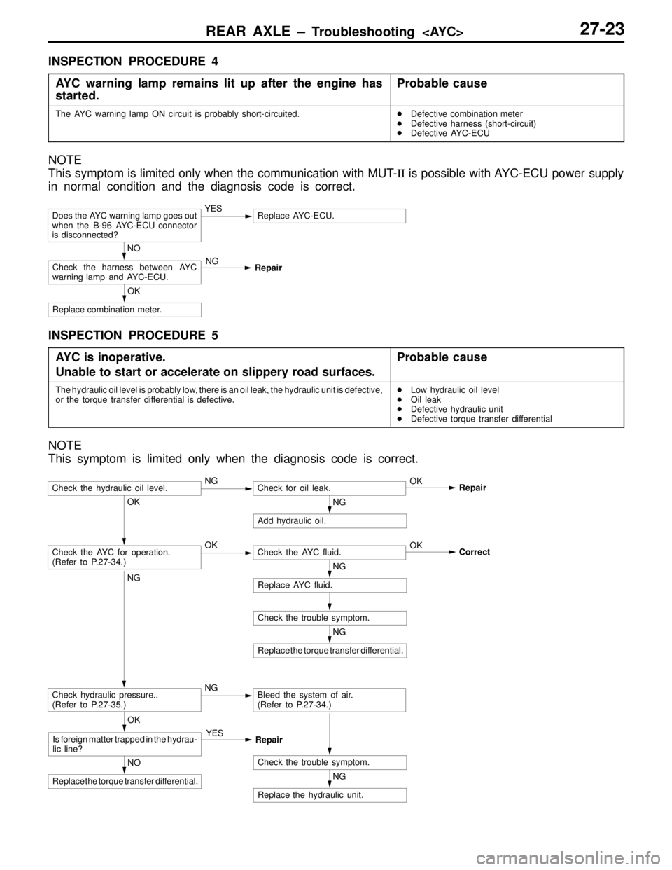
INSPECTION PROCEDURE 5
AYC is inoperative.
Unable to start or accelerate on slippery road surfaces.
Probable cause
The hydraulic oil level is probably low, there is an oil leak, the hydraulic unit is defective,
or the torque transfer differential is defective.�Low hydraulic oil level
�Oil leak
�Defective hydraulic unit
�Defective torque transfer differential
NOTE
This symptom is limited only when the diagnosis code is correct.
NG
Replace the hydraulic unit.
NG
Replace the torque transfer differential.
Check the trouble symptom.
NG
Replace AYC fluid.
OK
Correct
Check the trouble symptom.NO
Replace the torque transfer differential.
OK
Is foreign matter trapped in the hydrau-
lic line?YES
Repair
OK
Check the AYC for operation.
(Refer to P.27-34.)OKCheck the AYC fluid.
NG
Add hydraulic oil.
NG
Check hydraulic pressure..
(Refer to P.27-35.)NGBleed the system of air.
(Refer to P.27-34.)
Check the hydraulic oil level.NGCheck for oil leak.OK
Repair
Page 220 of 558
REAR AXLE – Troubleshooting 27-24
INSPECTION PROCEDURE 6
Rear tires are noisy during low-speed cornering.
Vehicle skews.
Probable cause
The hydraulic unit or torque transfer differential is probably defective.�Defective hydraulic unit
�Defective torque transfer differential
NOTE
This symptom is limited only when the diagnosis code is correct.
NG
Replace the hydraulic unit.
NG
Replace the torque transfer differential.
Check the trouble symptom.
NG
Replace AYC fluid.
OK
Correct
Check the trouble symptom.NO
Replace the torque transfer differential.
OK
Is foreign matter trapped in the hydrau-
lic line?YES
Repair
Check the AYC for operation..
(Refer to P.27-34.)OKCheck the AYC fluid.
NG
Check hydraulic pressure.
(Refer to P.27-35.)NGBleed the system of air..
(Refer to P.27-34.)