Page 26 of 558

11-1
ENGINE
CONTENTS
GENERAL INFORMATION 2. . . . . . . . . . . . . . . .
SPECIFICATIONS 3. . . . . . . . . . . . . . . . . . . . . . . .
Service Specifications 3. . . . . . . . . . . . . . . . . . . . . .
Torque Specifications 5. . . . . . . . . . . . . . . . . . . . . .
New Tightening Method by Use of Bolts
to Be Tightened in Plastic Area 9. . . . . . . . . . . .
Sealants 9. . . . . . . . . . . . . . . . . . . . . . . . . . . . . . . . . .
Form-In-Place Gasket 10. . . . . . . . . . . . . . . . . . . .
SPECIAL TOOLS 11. . . . . . . . . . . . . . . . . . . . . . .
ALTERNATOR AND IGNITION SYSTEM 14.
TIMING BELT 15. . . . . . . . . . . . . . . . . . . . . . . . .
FUEL AND EMISSION CONTROL PARTS 27
SECONDARY AIR SYSTEM AND INTAKE
MANIFOLD 29. . . . . . . . . . . . . . . . . . . . . . . . . . . . EXHAUST MANIFOLD 31. . . . . . . . . . . . . . . . .
WATER PUMP AND WATER HOSE 34. . . . .
ROCKER ARMS AND CAMSHAFT 37. . . . . .
CYLINDER HEAD AND VALVES 43. . . . . . . .
FRONT CASE, COUNTERBALANCE
SHAFT AND OIL PAN 51. . . . . . . . . . . . . . . . .
PISTON AND CONNECTING ROD 59. . . . . .
CRANKSHAFT AND FLYWHEEL 67. . . . . . . .
THROTTLE BODY 73. . . . . . . . . . . . . . . . . . . . .
TURBOCHARGER 75. . . . . . . . . . . . . . . . . . . . .
ALTERNATOR 79. . . . . . . . . . . . . . . . . . . . . . . . .
STARTER MOTOR 83. . . . . . . . . . . . . . . . . . . . .
Page 28 of 558

ENGINE – Specifications11-3
SPECIFICATIONS
SERVICE SPECIFICATIONS
ItemsStandard valueLimit
Timing belt
Auto-tensioner rod projection length mm12–
Auto-tensioner rod pushed-in amount [when pushed with a force of 98
– 196 N] mm1.0 or less–
Rocker arms and camshaft
Camshaft cam height mmIntake35.7935.29
Exhaust35.4934.99
Camshaft journal outer diameter mm26–
Cylinder head and valves
Cylinder head flatness of gasket surface mmLess than 0.050.2
Cylinder head grinding limit of gasket surface mm
Total resurfacing depth of both cylinder head and cylinder block–0.2
Cylinder head overall height mm131.9 – 132.1–
Cylinder head bolt shank length mm–Maximum 99.4
Valve thickness of valve head (margin) mmIntake1.00.5
Exhaust1.51.0
Overall valve length mmIntake109.5109.0
Exhaust109.7109.2
Valve thickness to valve guide clearance
mm
Intake0.02 – 0.050.10
mmExhaust0.05 – 0.090.15
Valve face angle45° – 45.5°–
Valve spring free length mm48.347.3
Valve spring load/installed height N/mm294/40.0–
Valve spring out-of-squareness1.5° or lessMaximum 4°
Valve seat contact width mm0.9 – 1.3–
Valve guide inner diameter mm6.6–
Valve guide projection from cylinder head upper surface mm20.5–
Valve stem projection mmIntake49.2049.70
Exhaust48.4048.90
Oversize rework dimensions of valve guide
hole mm
0.05 O.S.12.05 – 12.07–
hole mm0.25 O.S.12.25 – 11.27–
0.50 O.S.12.50 – 12.52–
Page 30 of 558
ENGINE – Specifications11-5
ItemsLimit Standard value
Alternator
Rotor coil resistance ΩApprox. 3 – 5–
Protrusion length of brush mm–2
Starter motor
Commutator runout mm0.050.1
Commutator outer diameter mm32.031.4
Commutator undercut mm0.5–
TORQUE SPECIFICATIONS
ItemsNm
Alternator and ignition system
Oil level gauge guide13
Water pump pulley9
Alternator brace (Alternator side)21
Alternator brace (Tightened with water pump)23
Alternator pivot bolt44
Crankshaft pulley25
Center cover3
Spark plug25
Ignition coil10
Timing belt
Timing belt cover (Flange bolt)11
Timing belt cover (Washer bolt)9
Power steering pump bracket49
Tensioner pulley49
Tensioner arm24
Auto tensioner24
Idler pulley48
Crank angle sensor9
Oil pump sprocket54
Camshaft bolt11 8
Tensioner “B”19
Counterbalance shaft sprocket45
Page 31 of 558
ENGINE – Specifications11-6
ItemsNm
Rocker cover3.5
Engine support bracket49
Camshaft sprocket bolt88
Timing belt rear right cover11
Timing belt rear left upper cover11
Fuel and emission control parts
Throttle body18
Fuel pressure regulator9
Delivery pipe11
Vacuum tank bracket9
Solenoid valve bracket9
Solenoid valve9
Vacuum hose and vacuum pipe11
Secondary air intake manifold
Heat protector13
Vacuum hose and vacuum pipe11
Air pipe (Heat protector side)13
Air pipe (Cam position sensor side)11
Air pipe (Eye bolt)49
Air pipe (Control valve side)24
Air control valve21
Air control valve bracket24
Intake manifold stay30
Intake manifold (M8)19
Intake manifold (M10)35
Exhaust manifold
Engine hanger12
Heat protector (Turbocharger side)14
Oxygen sensor54
Exhaust fitting bolt59
Exhaust fitting nut59
Air outlet fitting19
Page 36 of 558
ENGINE – Special Tools11-11
SPECIAL TOOLS
ToolNumberNameUse
MD998781Flywheel stopperHolding of flywheel and drive plate
MD998778Crankshaft
sprocket pullerRemoval of crankshaft sprocket
MD998719Pulley holder pinHolding camshaft sprocket
MB990767Crankshaft pulley
holder
MD998785Sprocket stopperHolding silent shaft sprocket
MD998767Tensioner puller
socket wrenchAdjustment of timing belt tension
MD998738Set screw
MD998713Camshaft oil seal
installerInstallation of camshaft oil seal
MD998442Lash adjuster wireAir bleeding of lash adjuster
Page 40 of 558

ENGINE – Timing Belt11-15
TIMING BELT
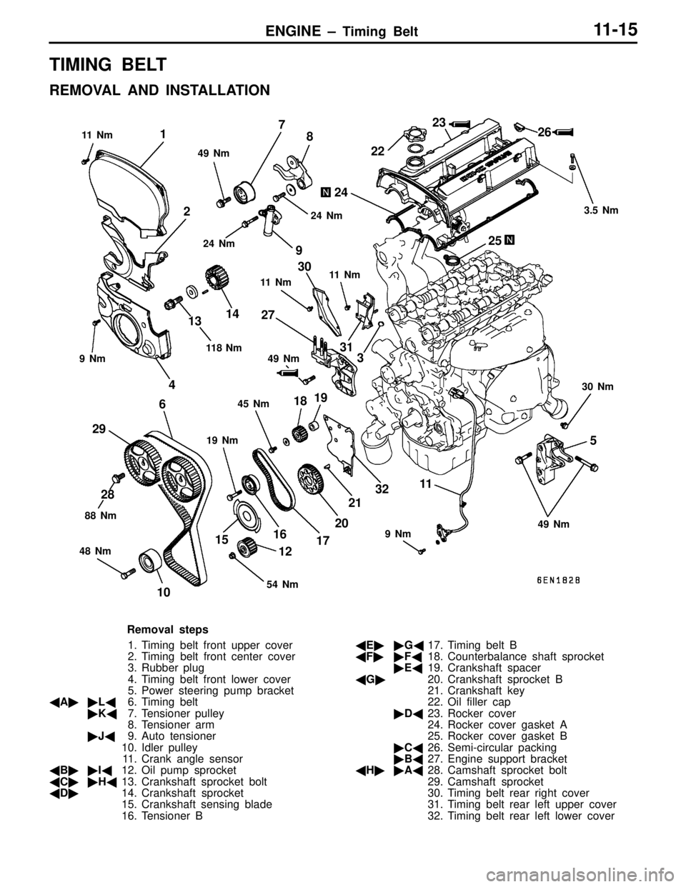
REMOVAL AND INSTALLATION
1
2
3
4
5 67
8
9
1011
12 1314
1516
17 1819
20212223
24
2526
27
28 2930
31
32
9 Nm
9 Nm 49 Nm 11 N m
11 N m
19 Nm 3.5 Nm
30 Nm
45 Nm 49 Nm 11 8 N m
88 Nm
48 Nm 49 Nm 11 N m
24 Nm
24 Nm
54 Nm
Removal steps
1. Timing belt front upper cover
2. Timing belt front center cover
3. Rubber plug
4. Timing belt front lower cover
5. Power steering pump bracket
�A��L�6. Timing belt
�K�7. Tensioner pulley
8. Tensioner arm
�J�9. Auto tensioner
10. Idler pulley
11. Crank angle sensor
�B��I�12. Oil pump sprocket
�C��H�13. Crankshaft sprocket bolt
�D�14. Crankshaft sprocket
15. Crankshaft sensing blade
16. Tensioner B�E��G�17. Timing belt B
�F��F�18. Counterbalance shaft sprocket
�E�19. Crankshaft spacer
�G�20. Crankshaft sprocket B
21. Crankshaft key
22. Oil filler cap
�D�23. Rocker cover
24. Rocker cover gasket A
25. Rocker cover gasket B
�C�26. Semi-circular packing
�B�27. Engine support bracket
�H��A�28. Camshaft sprocket bolt
29. Camshaft sprocket
30. Timing belt rear right cover
31. Timing belt rear left upper cover
32. Timing belt rear left lower cover
Page 41 of 558

ENGINE – Timing Belt11-16
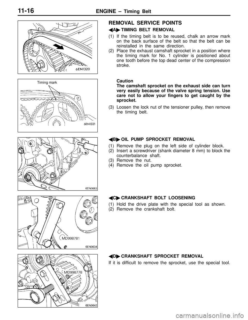
REMOVAL SERVICE POINTS
�A�TIMING BELT REMOVAL
(1) If the timing belt is to be reused, chalk an arrow mark
on the back surface of the belt so that the belt can be
reinstalled in the same direction.
(2) Place the exhaust camshaft sprocket in a position where
the timing mark for No. 1 cylinder is positioned about
one tooth before the top dead center of the compression
stroke.
Caution
The camshaft sprocket on the exhaust side can turn
very easily because of the valve spring tension. Use
care not to allow your fingers to get caught by the
sprocket.
(3) Loosen the lock nut of the tensioner pulley, then remove
the timing belt.
�B�OIL PUMP SPROCKET REMOVAL
(1) Remove the plug on the left side of cylinder block.
(2) Insert a screwdriver (shank diameter 8 mm) to block the
counterbalance shaft.
(3) Remove the nut.
(4) Remove the oil pump sprocket.
�C�CRANKSHAFT BOLT LOOSENING
(1) Hold the drive plate with the special tool as shown.
(2) Remove the crankshaft bolt.
�D�CRANKSHAFT SPROCKET REMOVAL
If it is difficult to remove the sprocket, use the special tool.
Timing mark
Page 42 of 558

ENGINE – Timing BeltENGINE – Timing Belt11-17
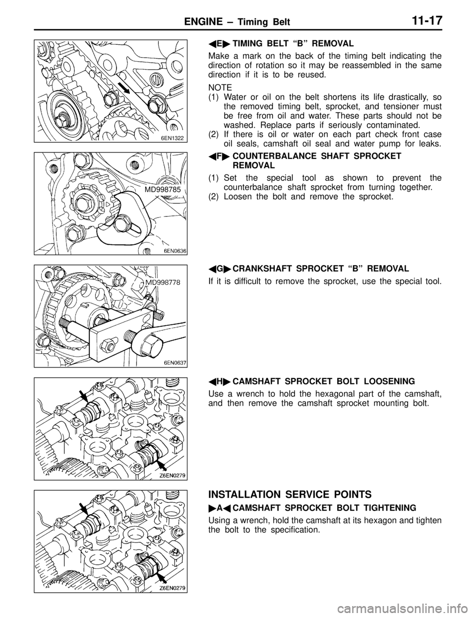
�E�TIMING BELT “B” REMOVAL
Make a mark on the back of the timing belt indicating the
direction of rotation so it may be reassembled in the same
direction if it is to be reused.
NOTE
(1) Water or oil on the belt shortens its life drastically, so
the removed timing belt, sprocket, and tensioner must
be free from oil and water. These parts should not be
washed. Replace parts if seriously contaminated.
(2) If there is oil or water on each part check front case
oil seals, camshaft oil seal and water pump for leaks.
�F�COUNTERBALANCE SHAFT SPROCKET
REMOVAL
(1) Set the special tool as shown to prevent the
counterbalance shaft sprocket from turning together.
(2) Loosen the bolt and remove the sprocket.
�G�CRANKSHAFT SPROCKET “B” REMOVAL
If it is difficult to remove the sprocket, use the special tool.
�H�CAMSHAFT SPROCKET BOLT LOOSENING
Use a wrench to hold the hexagonal part of the camshaft,
and then remove the camshaft sprocket mounting bolt.
INSTALLATION SERVICE POINTS
�A�CAMSHAFT SPROCKET BOLT TIGHTENING
Using a wrench, hold the camshaft at its hexagon and tighten
the bolt to the specification.
6EN1322
MD998785