Page 1191 of 1529
AIR CONDITIONING
82-2DESCRIPTION AND OPERATION
A/C control system component layout
RH drive shown, LH drive similar
1Air temperature control ECU
2Heater coolant temperature sensor
3Evaporator temperature sensor
4Dual pressure switch5Ambient temperature sensor
6Sunlight sensor
7In-car temperature sensor
Page 1192 of 1529

AIR CONDITIONING
DESCRIPTION AND OPERATION 82-3
Description
General
The air conditioning system controls the temperature, distribution and volume of air supplied to the vehicle interior to
provide a comfortable cabin environment. The system is electronically controlled and features automatic and manual
modes of operation, with separate temperature control of the LH and RH air outlets. The automatic modes provide
optimum control of the system under most ambient conditions and require no manual intervention. The manual modes
allow individual functions of automatic operation to be overridden, to accommodate personal preferences.
The air conditioning system consists of a refrigerant system, a heater assembly and a control system. It also uses the
same air inlet duct and distribution ducts as the Heating and Ventilation system on non air conditioned vehicles.
+ HEATING AND VENTILATION, DESCRIPTION AND OPERATION, Description.
Fresh or recirculated inlet air flows into the heater assembly from the blower in the air inlet duct. In the heater
assembly, the air is cooled and/or heated, depending on the selected cabin temperature and ambient conditions, then
directed to selected air outlets.
On vehicles with rear air conditioning, additional cooling is provided by recirculating air through a second evaporator
and distributing it to outlets in the roof.
+ AIR CONDITIONING, DESCRIPTION AND OPERATION, Description.
Page 1193 of 1529

AIR CONDITIONING
82-4DESCRIPTION AND OPERATION
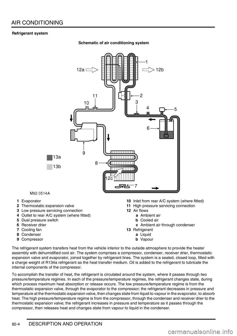
Refrigerant system
Schematic of air conditioning system
1Evaporator
2Thermostatic expansion valve
3Low pressure servicing connection
4Outlet to rear A/C system (where fitted)
5Dual pressure switch
6Receiver drier
7Cooling fan
8Condenser
9Compressor10Inlet from rear A/C system (where fitted)
11High pressure servicing connection
12Air flows
aAmbient air
bCooled air
cAmbient air through condenser
13Refrigerant
aLiquid
bVapour
The refrigerant system transfers heat from the vehicle interior to the outside atmosphere to provide the heater
assembly with dehumidified cool air. The system comprises a compressor, condenser, receiver drier, thermostatic
expansion valve and evaporator, joined together by refrigerant lines. The system is a sealed, closed loop, filled with
a charge weight of R134a refrigerant as the heat transfer medium. Oil is added to the refrigerant to lubricate the
internal components of the compressor.
To accomplish the transfer of heat, the refrigerant is circulated around the system, where it passes through two
pressure/temperature regimes. In each of the pressure/temperature regimes, the refrigerant changes state, during
which process maximum heat absorption or release occurs. The low pressure/temperature regime is from the
thermostatic expansion valve, through the evaporator to the compressor; the refrigerant decreases in pressure and
temperature at the thermostatic expansion valve, then changes state from liquid to vapour in the evaporator, to absorb
heat. The high pressure/temperature regime is from the compressor, through the condenser and receiver drier to the
thermostatic expansion valve; the refrigerant increases in pressure and temperature as it passes through the
compressor, then releases heat and changes state from vapour to liquid in the condenser.
Page 1197 of 1529

AIR CONDITIONING
82-8DESCRIPTION AND OPERATION
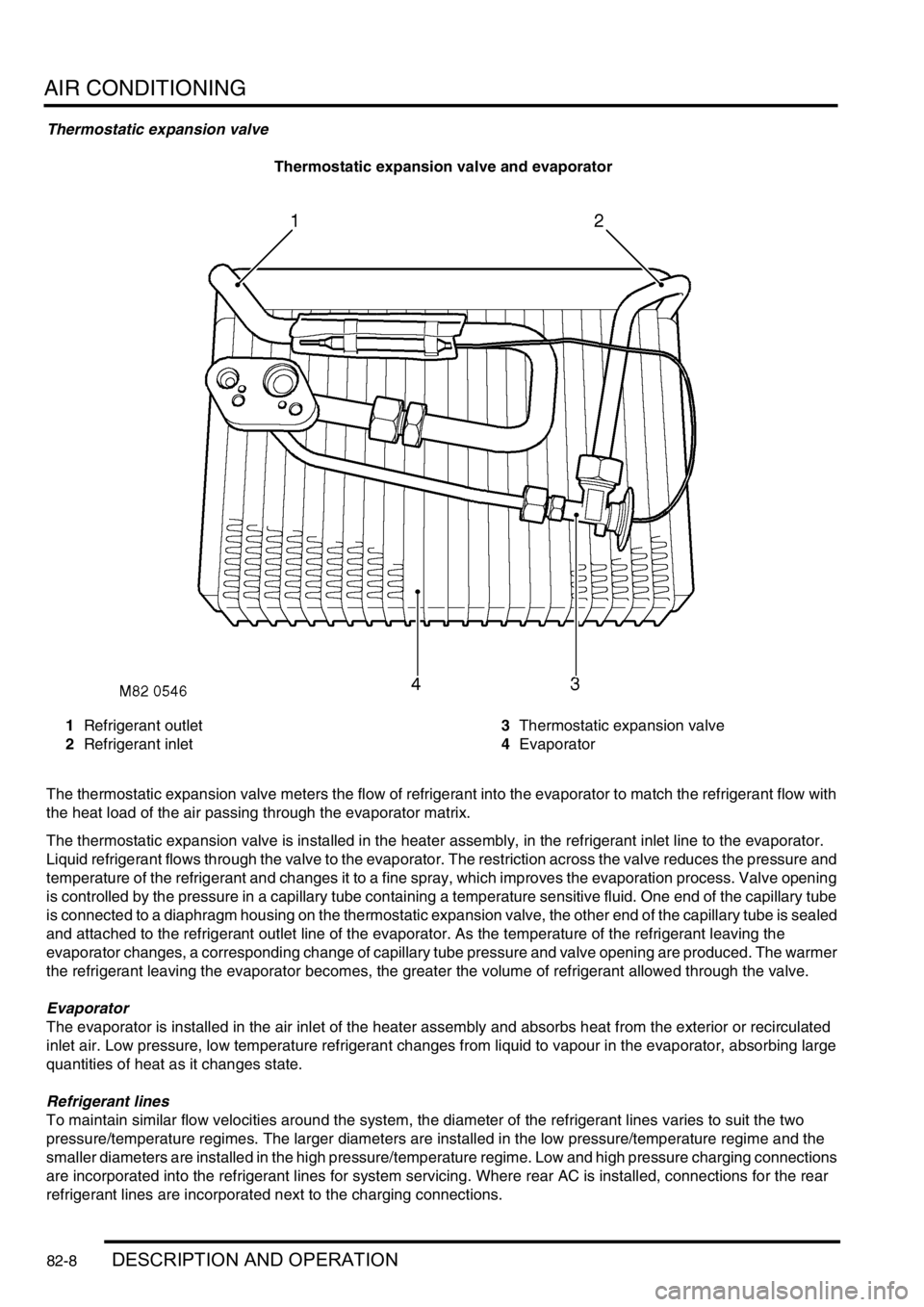
Thermostatic expansion valve
Thermostatic expansion valve and evaporator
1Refrigerant outlet
2Refrigerant inlet3Thermostatic expansion valve
4Evaporator
The thermostatic expansion valve meters the flow of refrigerant into the evaporator to match the refrigerant flow with
the heat load of the air passing through the evaporator matrix.
The thermostatic expansion valve is installed in the heater assembly, in the refrigerant inlet line to the evaporator.
Liquid refrigerant flows through the valve to the evaporator. The restriction across the valve reduces the pressure and
temperature of the refrigerant and changes it to a fine spray, which improves the evaporation process. Valve opening
is controlled by the pressure in a capillary tube containing a temperature sensitive fluid. One end of the capillary tube
is connected to a diaphragm housing on the thermostatic expansion valve, the other end of the capillary tube is sealed
and attached to the refrigerant outlet line of the evaporator. As the temperature of the refrigerant leaving the
evaporator changes, a corresponding change of capillary tube pressure and valve opening are produced. The warmer
the refrigerant leaving the evaporator becomes, the greater the volume of refrigerant allowed through the valve.
Evaporator
The evaporator is installed in the air inlet of the heater assembly and absorbs heat from the exterior or recirculated
inlet air. Low pressure, low temperature refrigerant changes from liquid to vapour in the evaporator, absorbing large
quantities of heat as it changes state.
Refrigerant lines
To maintain similar flow velocities around the system, the diameter of the refrigerant lines varies to suit the two
pressure/temperature regimes. The larger diameters are installed in the low pressure/temperature regime and the
smaller diameters are installed in the high pressure/temperature regime. Low and high pressure charging connections
are incorporated into the refrigerant lines for system servicing. Where rear AC is installed, connections for the rear
refrigerant lines are incorporated next to the charging connections.
Page 1198 of 1529
AIR CONDITIONING
DESCRIPTION AND OPERATION 82-9
Heater assembly
1Distribution servo motor
2Refrigerant inlet and outlet connector block
3RH blend flap servo motor4Thermostatic expansion valve
5LH blend flap servo motor
The heater assembly controls the temperature and distribution of air supplied to the distribution ducts, and is similar
to the heater assembly installed in non A/C vehicles.
+ HEATING AND VENTILATION, DESCRIPTION AND OPERATION, Description. The only differences from
the heater assembly in non A/C vehicles are as follows:
lThe thermostatic expansion valve, evaporator and evaporator temperature sensor are installed at the air inlet
side of the casing.
lThree servo motors operate the control flaps instead of control cables.
lA coolant temperature sensor is installed against the heater matrix.
The servo motors are controlled by the ATC ECU. Feedback potentiometers in the servo motors provide the ATC ECU
with flap position signals.
Page 1199 of 1529
AIR CONDITIONING
82-10DESCRIPTION AND OPERATION
Temperature and distribution control
Figure shows flaps set for medium heat to face level and footwell outlets
1Windscreen/Side windows outlet
2Heater assembly casing
3Air inlet
4Evaporator5Heater matrix
6Front footwells outlet
7Rear footwells outlet
8Face level outlet
Control system
The control system operates the refrigerant system and the control flaps in the heater assembly to control the
temperature and distribution of air in the vehicle interior. It also outputs signals to the fresh/recirculated air servo motor
and the blower to control the volume and source of inlet air. The control system consists of:
lAn Air Temperature Control (ATC) ECU.
lA dual pressure switch.
lAn evaporator temperature sensor.
lAn in-car temperature sensor.
lA sunlight sensor.
lA heater coolant temperature sensor.
lAn ambient temperature sensor.
Page 1200 of 1529

AIR CONDITIONING
DESCRIPTION AND OPERATION 82-11
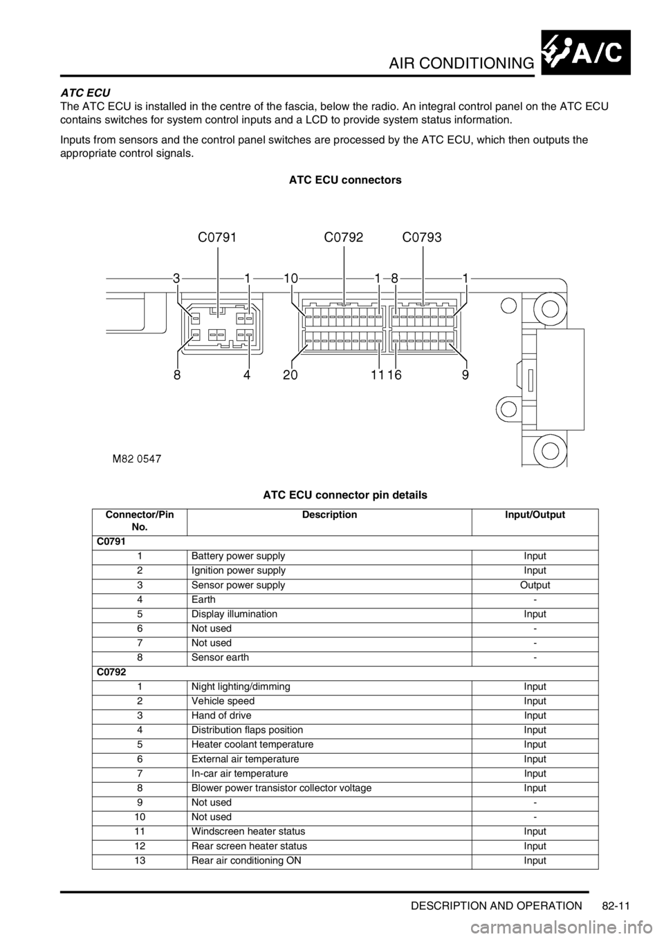
ATC ECU
The ATC ECU is installed in the centre of the fascia, below the radio. An integral control panel on the ATC ECU
contains switches for system control inputs and a LCD to provide system status information.
Inputs from sensors and the control panel switches are processed by the ATC ECU, which then outputs the
appropriate control signals.
ATC ECU connectors
ATC ECU connector pin details
Connector/Pin
No.Description Input/Output
C0791
1 Battery power supply Input
2 Ignition power supply Input
3 Sensor power supply Output
4Earth -
5 Display illumination Input
6 Not used -
7 Not used -
8 Sensor earth -
C0792
1 Night lighting/dimming Input
2 Vehicle speed Input
3 Hand of drive Input
4 Distribution flaps position Input
5 Heater coolant temperature Input
6 External air temperature Input
7 In-car air temperature Input
8 Blower power transistor collector voltage Input
9 Not used -
10 Not used -
11 Windscreen heater status Input
12 Rear screen heater status Input
13 Rear air conditioning ON Input
Page 1201 of 1529

AIR CONDITIONING
82-12DESCRIPTION AND OPERATION
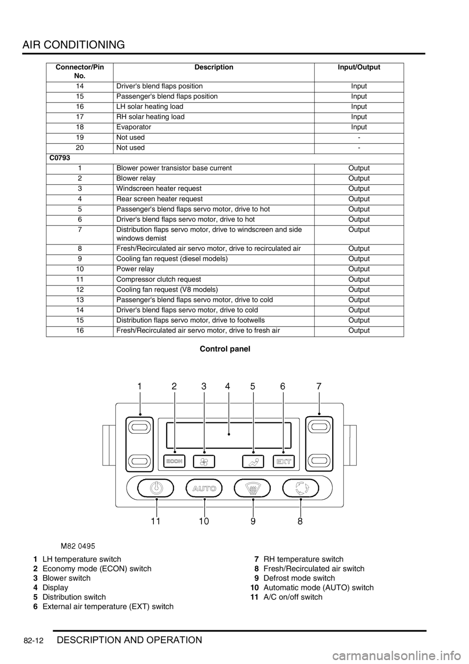
Control panel
1LH temperature switch
2Economy mode (ECON) switch
3Blower switch
4Display
5Distribution switch
6External air temperature (EXT) switch7RH temperature switch
8Fresh/Recirculated air switch
9Defrost mode switch
10Automatic mode (AUTO) switch
11A/C on/off switch
14 Driver's blend flaps position Input
15 Passenger's blend flaps position Input
16 LH solar heating load Input
17 RH solar heating load Input
18 Evaporator Input
19 Not used -
20 Not used -
C0793
1 Blower power transistor base current Output
2 Blower relay Output
3 Windscreen heater request Output
4 Rear screen heater request Output
5 Passenger's blend flaps servo motor, drive to hot Output
6 Driver's blend flaps servo motor, drive to hot Output
7 Distribution flaps servo motor, drive to windscreen and side
windows demistOutput
8 Fresh/Recirculated air servo motor, drive to recirculated air Output
9 Cooling fan request (diesel models) Output
10 Power relay Output
11 Compressor clutch request Output
12 Cooling fan request (V8 models) Output
13 Passenger's blend flaps servo motor, drive to cold Output
14 Driver's blend flaps servo motor, drive to cold Output
15 Distribution flaps servo motor, drive to footwells Output
16 Fresh/Recirculated air servo motor, drive to fresh air Output Connector/Pin
No.Description Input/Output