1999 LAND ROVER DISCOVERY rear entertainment
[x] Cancel search: rear entertainmentPage 30 of 1529

CONTENTS
CONTENTS 27
WINDOWS ................................................................................................ 86-5-1
DESCRIPTION AND OPERATION
Electric windows block diagram ...................................................................................................... 86-5-1
Electric windows component layout ................................................................................................ 86-5-2
Description ...................................................................................................................................... 86-5-4
Operation ....................................................................................................................................... 86-5-11
REPAIRS
Switch - rear door .......................................................................................................................... 86-5-13
Switch - console ............................................................................................................................ 86-5-13
Switch - heated rear screen ............................................................................................................ 86-5-14
IN CAR ENTERTAINMENT ...................................................................... 86-6-1
DESCRIPTION AND OPERATION
ICE System Component layout ....................................................................................................... 86-6-1
Base and mid line ICE system control diagram .............................................................................. 86-6-2
High line ICE system control diagram ............................................................................................. 86-6-3
Description ...................................................................................................................................... 86-6-4
DESCRIPTION AND OPERATION
DVD Player Component Layout ...................................................................................................... 86-6-12
DVD Player Control Diagram .......................................................................................................... 86-6-14
Description ...................................................................................................................................... 86-6-16
Operation ........................................................................................................................................ 86-6-27
REPAIRS
Radio ............................................................................................................................................. 86-6-31
Speaker - low/full range - front door .............................................................................................. 86-6-32
Speaker - low range - rear door ..................................................................................................... 86-6-32
Switches - remote control - ICE .................................................................................................... 86-6-33
Amplifier - aerial .............................................................................................................................. 86-6-33
Speaker - mid range - front door ................................................................................................... 86-6-34
Speaker - high range - rear door ................................................................................................... 86-6-34
Amplifier - power ........................................................................................................................... 86-6-35
Speaker - tail door ......................................................................................................................... 86-6-36
CD autochanger ............................................................................................................................ 86-6-36
DVD screen/player unit .................................................................................................................. 86-6-37
Switch box - CD/DVD player ........................................................................................................... 86-6-38
HARNESSES ............................................................................................ 86-7-1
REPAIRS
Harness - injectors - diesel ............................................................................................................ 86-7-1
Harness - body .............................................................................................................................. 86-7-1
Harness - engine - V8 ..................................................................................................................... 86-7-8
Harness - engine - diesel ................................................................................................................ 86-7-12
Harness - main .............................................................................................................................. 86-7-15
Harness - main - DVD unit ............................................................................................................. 86-7-28
Harness - link - CD/DVD switch box ............................................................................................... 86-7-32
Page 34 of 1529

INTRODUCTION
01-3
Abbreviations and Symbols
A Amperes
AAP Ambient Air Pressure
ABDC After Bottom Dead Centre
ABS Anti-Lock Brake System
ac Alternating current
A/C Air Conditioning
ACE Active Cornering Enhancement
ACEA Association of Constructors of
European Automobiles
AFR Air Fuel Ratio
AP Ambient Pressure
ASC Anti-shunt Control
ATC Air Temperature Control
ATDC After Top Dead Centre
BBDC Before Bottom Dead Centre
BBUS Battery Backed Up Sounder
BCU Body Control Unit
BDC Bottom Dead Centre
bhp Brake Horse Power
BP Boost Pressure
BPP Brake Pedal Position
BS British Standard
BTDC Before Top Dead Centre
C Celsius
CAN Controller Area Network
CD Compact Disc
CDC Centre Differential Control
CDL Central Door Locking
CD - ROM Compact Disc - Read Only
Memory
CFC Chlorofluorocarbon
CHMSL Centre High Mounted Stop Lamp
CKP Crankshaft Position
CLV Calculated Load Value
cm Centimetre
cm
2Square centimetre
cm3Cubic centimetre
CMP Camshaft Position
CPP Clutch Pedal Position
CO Carbon Monoxide
CO
2Carbon Dioxide
CR Common Rail
CVS Canister Vent Solenoid
deg. Degree, angle or temperature
dia. Diameter
DIN Deutsche Industrie Normen
(German Industrial Standards)
dc Direct current
DCV Directional Control Valve
DOHC Double Overhead Camshaft
DTI Dial Test Indicator
DFM Dual Mass Flywheel
DVD Digital Versatile Disc
EACV Electronic Air Control Valve EAT Electronic Automatic
Transmission
EBD Electronic Brake pressure
Distribution
ECD European Community Directive
ECM Engine Control Module
ECT Engine Coolant Temperature
ECU Electronic Control Unit
EDC Electronic Diesel Control
EEPROM Electronic Erasable
Programmable Read Only
Memory
EGR Exhaust Gas Recirculation
EKA Emergency Key Access
EN European Norm
EOBD European On Board Diagnostics
ETC Electronic Traction Control
EUI Electronic Unit Injector
EVAP Evaporative Emission
EVR Electronic Vacuum Regulator
F Fahrenheit
FBH Fuel Burning Heater
FIP Fuel Injection Pump
FTC Fast Throttle Control
g Gramme or Gravity
hHour
hc High compression
HC Hydro Carbons
HDC Hill Descent Control
HDPE High Density Polyethylene
HFS Heated Front Screen
Hg Mercury
HO2S Heated Oxygen Sensor
HMW High Molecular Weight
HRW Heated Rear Window
ht/HT High tension
IACV Idle Air Control Valve
IAT Intake Air Temperature
ICE In-Car Entertainment
i.dia. Internal diameter
IDM Intelligent Driver Module
in3Cubic inch
ILT Inlet Throttle
ISO International Organisation for
Standardisation
k Thousand
kg Kilogramme
km Kilometre
km/h Kilometres per hour
kPa KiloPascal
KS Knock Sensor
lLitre
lbf.in Pounds force inches
lbf/in
2Pounds per square inch
lbf.ft Pounds force feet
Page 871 of 1529

BRAKES
70-18 DESCRIPTION AND OPERATION
The SLABS ECU continually calculates vehicle speed using the wheel speed inputs from all four ABS sensors. The
calculated vehicle speed is then used as a reference against which individual wheel speeds are monitored for
unacceptable acceleration or deceleration. The ABS sensor inputs are also used by the SLABS ECU to detect vehicle
deceleration rate, vehicle cornering rate and rough terrain.
The engaged forward gear and (on manual gearbox models) the clutch status are computed from the engine data
input, the engine speed input and vehicle speed. Reverse gear status is provided by an input from the reverse lamp
switch (manual gearbox models) or the BCU (automatic gearbox models). On automatic models, the BCU also
provides the neutral selected input.
In addition to controlling the brake related functions, the SLABS ECU:
lControls the operation of the self levelling suspension (SLS) system (where fitted).
+ REAR SUSPENSION, DESCRIPTION AND OPERATION, Description.
lOn V8 models, outputs a rough road signal to the ECM when traversing rough terrain.
lOutputs a vehicle speed signal.
The vehicle speed signal is output to the following systems (where fitted):
lActive Cornering Enhancement.
+ FRONT SUSPENSION, DESCRIPTION AND OPERATION, Description - ACE.
lAir conditioning.
+ AIR CONDITIONING, DESCRIPTION AND OPERATION, Description.
lCruise control.
+ ENGINE MANAGEMENT SYSTEM - Td5, DESCRIPTION AND OPERATION, Description.
+ ENGINE MANAGEMENT SYSTEM - V8, DESCRIPTION AND OPERATION, Description - engine
management.
lEngine management.
+ ENGINE MANAGEMENT SYSTEM - Td5, DESCRIPTION AND OPERATION, Description.
+ ENGINE MANAGEMENT SYSTEM - V8, DESCRIPTION AND OPERATION, Description - engine
management.
lIn-car entertainment.
+ IN CAR ENTERTAINMENT, DESCRIPTION AND OPERATION, Description.
lInstrument pack.
+ INSTRUMENTS, DESCRIPTION AND OPERATION, Description.
5 Front right inlet solenoid valve Output
6 Shuttle valve switches Input
7 Rear left outlet solenoid valve Output
8 Rear left inlet solenoid valve Output
9 Centre differential lock switch Input
10 Rear right outlet solenoid valve Output
11 Rear right inlet solenoid valve Output
12 Brake lamp relay Output
15 Return pump relay Output
C0655
7 Audible warning Output
10 Engine speed Input
Connector and pins not listed are either not used or used by the self levelling suspension system.
+ REAR SUSPENSION, DESCRIPTION AND OPERATION, Description.
Connector/Pin
No.Description Input/Output
Page 984 of 1529

INTERIOR TRIM COMPONENTS
REPAIRS 76-3-19
Carpet - rear
$% 76.49.03
Remove
1. Models with premium ICE: Remove power
amplifier.
+ IN CAR ENTERTAINMENT,
REPAIRS, Amplifier - power.
2.Remove RH front seat.
+ SEATS, REPAIRS, Seat - front.
3.Remove both 'B' post lower trim panels.
+ INTERIOR TRIM COMPONENTS,
REPAIRS, Trim casing - lower - 'B' post.
4.Remove finishers from front and rear carpet
retainers.
5.Remove 12 screws securing front and rear
carpet retainers to floor.
6.Remove front and rear carpet retainers. 7.Remove 4 screws securing trim panel to rear of
centre console.
8.Remove trim panel.
9.Position harnesses clear of rear carpet.
10.Remove rear carpet.
Refit
1.Position new rear carpet.
2.Fit front and rear carpet retainers to floor and
secure with screws.
3.Fit finishers to front and rear carpet retainers
4.Position trim panel to rear of centre console
and secure with screws.
5.Fit lower 'B' post trim panels.
+ INTERIOR TRIM COMPONENTS,
REPAIRS, Trim casing - lower - 'B' post.
6.Fit RH front seat to floor.
+ SEATS, REPAIRS, Seat - front.
7. Models with premium ICE: Fit power
amplifier.
+ IN CAR ENTERTAINMENT,
REPAIRS, Amplifier - power.
Page 1102 of 1529

PANEL REPAIRS
REPAIRS 77-2-35
'A' post assembly
In this procedure, the front wing and the valance
outer reinforcement (rear section) are replaced in
conjunction with the 'A' post assembly. The dash side
assembly can also be replaced in this procedure if
required.
Remove
1.Disconnect both battery leads, negative lead
first.
2.Disconnect leads/multiplug from alternator.
3.Remove bonnet.
4.Remove front wing.
+ EXTERIOR FITTINGS, REPAIRS,
Wing - front - up to 03MY.
5.Remove RH or LH front door.
+ DOORS, REPAIRS, Door - front.
6.Remove RH or LH sill finisher.
7.Remove windscreen.
+ SCREENS, REPAIRS, Windscreen.
8. Diesel models: Remove ECM.
+ ENGINE MANAGEMENT SYSTEM -
Td5, REPAIRS, Engine control module
(ECM).
9.Remove RH or LH 'A' post inner finishers and
disconnect speaker multiplug (if fitted).
10.Release sunroof drain tube and position aside.
11.Remove RH or LH front seat.
+ SEATS, REPAIRS, Seat - front.
12. RH side: Remove CD autochanger.
+ IN CAR ENTERTAINMENT,
REPAIRS, CD autochanger.
13.Remove fascia.
+ INTERIOR TRIM COMPONENTS,
REPAIRS, Fascia.
14. Driver's side: Remove steering column
support bracket.
15.Remove relevant wiring from 'A' post.
16.Remove tread plate from front door aperture.
17.Release front carpet and position aside.
18.Remove front door aperture seal.
19.Remove engine bulkhead insulation.Repair
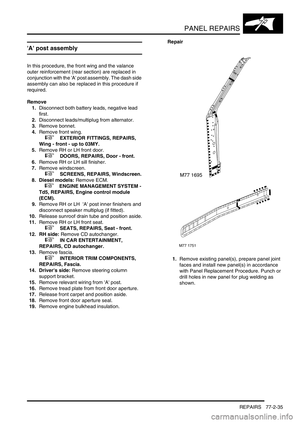
1.Remove existing panel(s), prepare panel joint
faces and install new panel(s) in accordance
with Panel Replacement Procedure. Punch or
drill holes in new panel for plug welding as
shown.
M77 1751
Page 1105 of 1529

PANEL REPAIRS
77-2-38 REPAIRS
Sill outer assembly
Remove
1.Disconnect both battery leads, negative lead
first.
2.Disconnect leads/multiplug from alternator.
3.Remove RH or LH front wing.
+ EXTERIOR FITTINGS, REPAIRS,
Wing - front - up to 03MY.
4.Remove RH or LH front door.
+ DOORS, REPAIRS, Door - front.
5.Remove RH or LH rear door.
+ DOORS, REPAIRS, Door - rear.
6.Remove RH or LH sill finisher.
7.Remove RH or LH 'A' post inner lower
finishers.
8.Remove RH or LH front seat.
+ SEATS, REPAIRS, Seat - front.
9. LH side: Remove power amplifier and EAT
ECU.
+ IN CAR ENTERTAINMENT,
REPAIRS, Amplifier - power.
10. RH side: Remove CD autochanger.
+ IN CAR ENTERTAINMENT,
REPAIRS, CD autochanger.
11.Remove rear seats.
+ SEATS, REPAIRS, Seat - rear.
12.Remove RH or LH front seat belt.
+ RESTRAINT SYSTEMS, REPAIRS,
Seat belt - front.
13.Remove tread plates from front and rear door
apertures.
14.Release carpet and position aside.
15.Remove front and rear door aperture seals.
16.Release relevant wiring from 'A' post, 'B/C' post
and sill areas, and position aside.
17.Remove loadspace lower trim casing.
+ INTERIOR TRIM COMPONENTS,
REPAIRS, Trim casing - side - loadspace.
18. RH side: Remove lower ACE accelerometer.
+ FRONT SUSPENSION, REPAIRS,
Accelerometer - ACE - lower.
19. LH side: Remove SLS air compressor unit.
+ REAR SUSPENSION, REPAIRS,
Compressor unit - air - SLS.
20. Models with rear A/C: Recover refrigerant
from A/C system and remove A/C pipes from
LH sill.
+ AIR CONDITIONING, REFRIGERANT
RECOVERY, RECYCLING AND
RECHARGING, Refrigerant recovery,
recycling and recharging.
21.Remove 2 bolts securing body to chassis.Repair
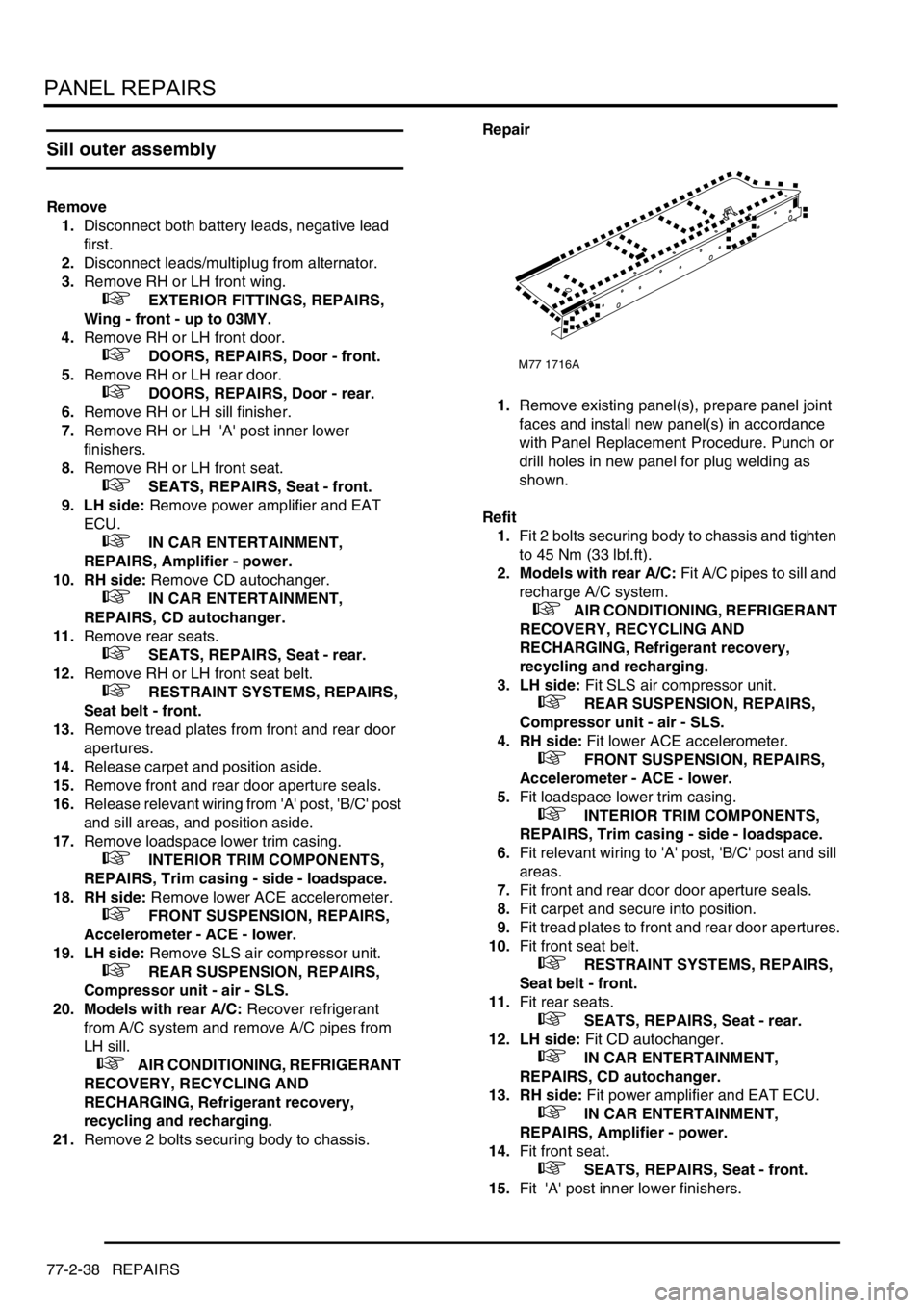
1.Remove existing panel(s), prepare panel joint
faces and install new panel(s) in accordance
with Panel Replacement Procedure. Punch or
drill holes in new panel for plug welding as
shown.
Refit
1.Fit 2 bolts securing body to chassis and tighten
to 45 Nm (33 lbf.ft).
2. Models with rear A/C: Fit A/C pipes to sill and
recharge A/C system.
+ AIR CONDITIONING, REFRIGERANT
RECOVERY, RECYCLING AND
RECHARGING, Refrigerant recovery,
recycling and recharging.
3. LH side: Fit SLS air compressor unit.
+ REAR SUSPENSION, REPAIRS,
Compressor unit - air - SLS.
4. RH side: Fit lower ACE accelerometer.
+ FRONT SUSPENSION, REPAIRS,
Accelerometer - ACE - lower.
5.Fit loadspace lower trim casing.
+ INTERIOR TRIM COMPONENTS,
REPAIRS, Trim casing - side - loadspace.
6.Fit relevant wiring to 'A' post, 'B/C' post and sill
areas.
7.Fit front and rear door door aperture seals.
8.Fit carpet and secure into position.
9.Fit tread plates to front and rear door apertures.
10.Fit front seat belt.
+ RESTRAINT SYSTEMS, REPAIRS,
Seat belt - front.
11.Fit rear seats.
+ SEATS, REPAIRS, Seat - rear.
12. LH side: Fit CD autochanger.
+ IN CAR ENTERTAINMENT,
REPAIRS, CD autochanger.
13. RH side: Fit power amplifier and EAT ECU.
+ IN CAR ENTERTAINMENT,
REPAIRS, Amplifier - power.
14.Fit front seat.
+ SEATS, REPAIRS, Seat - front.
15.Fit 'A' post inner lower finishers.
M77 1716A
Page 1107 of 1529

PANEL REPAIRS
77-2-40 REPAIRS
'B/C' post assembly
Remove
1.Disconnect both battery leads, negative lead
first.
2.Disconnect leads/multiplug from alternator.
3.Remove RH or LH rear door.
+ DOORS, REPAIRS, Door - rear.
4.Remove front door striker from 'B/C' post.
5.Remove RH or LH sill finisher.
6.Remove RH or LH front seat.
+ SEATS, REPAIRS, Seat - front.
7. RH side: Remove power amplifier.
+ IN CAR ENTERTAINMENT,
REPAIRS, Amplifier - power.
8. LH side: Remove CD autochanger.
+ IN CAR ENTERTAINMENT,
REPAIRS, CD autochanger.
9.Remove RH or LH front seat belt.
+ RESTRAINT SYSTEMS, REPAIRS,
Seat belt - front.
10.Remove RH or LH rear seat.
+ SEATS, REPAIRS, Seat - rear.
11.Remove head lining.
+ INTERIOR TRIM COMPONENTS,
REPAIRS, Headlining.
12.Remove tread plate from front and rear door
apertures.
13.Release carpet from fixings and position aside.
14.Remove front and rear door door aperture
seals.
15.Release relevant wiring from 'B/C' post and sill
areas and position aside.
16.Remove side drip rail finisher.Repair
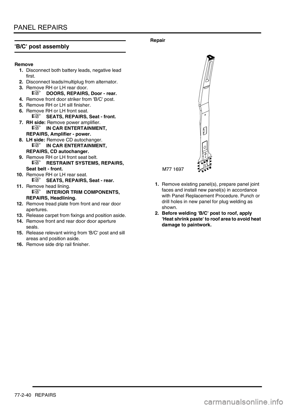
1.Remove existing panel(s), prepare panel joint
faces and install new panel(s) in accordance
with Panel Replacement Procedure. Punch or
drill holes in new panel for plug welding as
shown.
2. Before welding 'B/C' post to roof, apply
'Heat shrink paste' to roof area to avoid heat
damage to paintwork.
Page 1108 of 1529

PANEL REPAIRS
REPAIRS 77-2-41
Refit
1.Fit side drip rail finisher.
2.Fit wiring to 'B/C' post and sill areas.
3.Fit front and rear door door aperture seal.
4.Position carpet and secure with fixings.
5.Fit tread plates to front and rear door apertures.
6.Fit head lining.
+ INTERIOR TRIM COMPONENTS,
REPAIRS, Headlining.
7.Fit rear seat.
+ SEATS, REPAIRS, Seat - rear.
8.Fit front seat belt.
+ RESTRAINT SYSTEMS, REPAIRS,
Seat belt - front.
9. LH side: Fit CD autochanger.
+ IN CAR ENTERTAINMENT,
REPAIRS, CD autochanger.
10. RH side: Fit power amplifier.
+ IN CAR ENTERTAINMENT,
REPAIRS, Amplifier - power.
11.Fit RH or LH front seat.
+ SEATS, REPAIRS, Seat - front.
12.Fit sill finisher.
13.Fit front door striker to B/C post, fit Torx bolts
and tighten to 26 Nm (19 lbf.ft).
14.Fit rear door.
+ DOORS, REPAIRS, Door - rear.
15.Connect leads/multiplug to alternator.
16.Connect battery leads, negative lead last.
Panel body side assembly
Remove
1.Disconnect both battery leads, negative lead
first.
2.Disconnect leads/multiplug from alternator.
3.Remove loadspace side trim casing.
+ INTERIOR TRIM COMPONENTS,
REPAIRS, Trim casing - side - loadspace.
4.Remove head lining rear trim finisher.
5.Remove rear head rests, if fitted.
6.Remove body side rear glass.
+ SCREENS, REPAIRS, Glass - body
side - rear.
7.Remove rear bumper assembly.
+ EXTERIOR FITTINGS, REPAIRS,
Bumper assembly - rear - up to 03MY.
8.Remove rear bumper finisher.
9.Remove rear wheel arch liner.
+ EXTERIOR FITTINGS, REPAIRS,
Liner - wheel arch - rear.
10.Remove mud flap.
11.Remove tread plate from rear door aperture.
12.Remove rear door aperture seal.
13.Remove rear door striker from 'D' post.
14.Remove 'D' post outer trim finisher.
15.Remove wheel arch trim finisher.
16.Remove side drip rail finisher.
17. RH side: Remove tail door.
18. LH side: Remove tail door striker and setting
block from 'E' post.
19.Remove tail door tread plate.
20.Remove loadspace carpet retainer.
21.Remove tail door aperture seal.
22.Remove tail lamp.
+ LIGHTING, REPAIRS, Lamp - tail.
23. RH side: Remove fuel filler flap.
24. RH side: Remove fuel filler tube.
+ FUEL DELIVERY SYSTEM - V8,
REPAIRS, Filler tube - fuel.
25.Remove aerial amplifier.
26.Remove relevant wiring from body side area.