1999 LAND ROVER DISCOVERY heater
[x] Cancel search: heaterPage 1302 of 1529

BODY CONTROL UNIT
DESCRIPTION AND OPERATION 86-3-15
Electric seats
The BCU controls the logical operation of the electrically operated front seats. Two modes of operation are available:
+ SEATS, DESCRIPTION AND OPERATION, Description - electric seats.
lElectric seat adjustment is enabled if the ignition is on or the driver's door is opened for a short time period.
lElectric seat adjustment is enabled if the ignition is on and the driver's door is closed.
The seats are operated by four electric motors which control the seat cushion rear up/ down, the seat cushion front
up/ down, seat cushion forward/ rearward and seat squab recline. The electrically powered lumbar adjustment in each
seat is operated by a single motorised air pump and a solenoid located on the seat squab frame. The air pump inflates
a cushion in the seat squab and the solenoid operates a valve to deflate the cushion. The seat squab and cushion
may also contain heater elements to provide heated seat operation.
The switches for electrically operated seats are located either side of the centre console.
Direction indicators and hazard warning lamps
The direction indicator lamps are operated from a three position direction indicator switch on the left hand, steering
column stalk. The BCU only allows the lamps to work as direction indicators when the ignition switch is in position II.
The BCU also controls the lamps to operate as hazard warning lamps and as a visual warning for the anti-theft system,
in which cases all lamps flash simultaneously irrespective of the ignition switch position.
System control of the direction indicators and hazard warning lamps is provided by the BCU operating with the IDM
and two electronic relays located in the passenger compartment fuse box. The IDM and relays are integral parts of
the passenger compartment fuse box and cannot be serviced individually. The serial data bus is used for
communication of status and operation requests between the BCU, IDM and instrument pack.
The hazard warning lamps are operated from a latching pushbutton switch located on the fascia.
All direction indicator/ hazard warning lamp bulbs are rated at 5 Watts.
Headlamps
The BCU contains a feature which allow the vehicle headlamps to be turned on when the remote transmitter is
pressed (courtesy headlamps).
For markets with daylight running lamps, the BCU controls the logical operation of the daylight running lamps. Options
are daylight running lamps are on if the main beam headlamps are off, or the daylight running lamps are on with main
and dipped beam off and the gearbox not in Park.
Front fog lamps
For markets with front fog lamps fitted, the BCU controls the operation of the front fog lamps. Options can be selected
so that the fog lamps will operate with or without the headlamps on main beam.
Instrument pack
The BCU communicates with the instrument pack via a serial data bus.
+ INSTRUMENTS, DESCRIPTION AND OPERATION, Description.
lThe instrument pack provides the BCU and IDM with details of vehicle speed.
lSignals are provided from the IDM to the instrument pack and BCU when the direction indicator lamps are active.
lFor certain markets, the BCU provides a signal to the instrument pack for indicating when the transfer box is in
neutral.
lThe IDM can signal the instrument pack to illuminate a trailer warning lamp. This operates when the IDM senses
that the current drawn by the indicator circuit exceeds a preset threshold.
lThe odometer reading displayed on the instrument pack LCD screen is also stored in non volatile memory in the
BCU. Whenever the ignition is turned from position I to position II, the instrument pack and the BCU compare
their stored values.
lThe gear selector position is displayed on the instrument pack LCD screen under the direction of the BCU.
Starting
The starting system comprises a starter motor and solenoid located at the rear right hand side of the engine. A starter
relay controlled by the BCU is used to supply battery power for starter solenoid operation. The starter motor receives
its feed directly from the battery.
Page 1417 of 1529

HARNESSES
86-7-12 REPAIRS
Refit
1.Position engine harness around engine.
2.Connect oil pressure switch and camshaft
sensor multiplugs.
3.Fit and tighten bolt securing harness to LH side
of engine.
4.Connect both knock sensor multiplugs.
5.Connect battery cable and solenoid cable to
starter motor.
6.Position starter heat shield and secure with
bolt.
7.Clean exhaust flange mating faces, using a
new gasket align exhaust fit nuts and tighten to
60 Nm (44 lbf.ft).
8.Remove stand(s) and lower vehicle.
9.Position harness into footwell and secure
grommet.
10.Connect ECM multiplugs.
11.Position toe board and secure with trim fixings.
12.Connect engine harness to main harness
multiplug and secure earth lead.
13.Connect EVAP solenoid multiplug.
14.Connect both fuse box multiplugs.
15.Position starter lead to fuse box and secure
screw.
16.Fit fuse box cover.
17.Position battery positive lead to battery and
secure nut.
18.Secure harness to coolant rail.
19.Position alternator cables and tighten terminal
B+ to 18 Nm (13 lbf.ft) and terminal D+ to 5 Nm
(3.7 lbf.ft)
20.Connect coolant temperature sensor multiplug.
21.Connect A/C compressor multiplug.
22.Secure harness clip to rear of LH cylinder head.
23.Connect CKP sensor multiplug.
24.Secure injector harness and connect injector
multiplugs.
25.Connect coil multiplugs.
26.Connect and secure HS
2O sensor multiplug
27.Fit upper inlet manifold.
+ MANIFOLDS AND EXHAUST
SYSTEMS - V8, REPAIRS, Gasket - inlet
manifold - upper - Without Secondary Air
Injection.
28.Connect battery earth lead.
Harness - engine - diesel
$% 86.70.17
Remove
1.Remove engine acoustic cover.
2.Remove battery carrier.
+ CHARGING AND STARTING,
REPAIRS, Battery carrier.
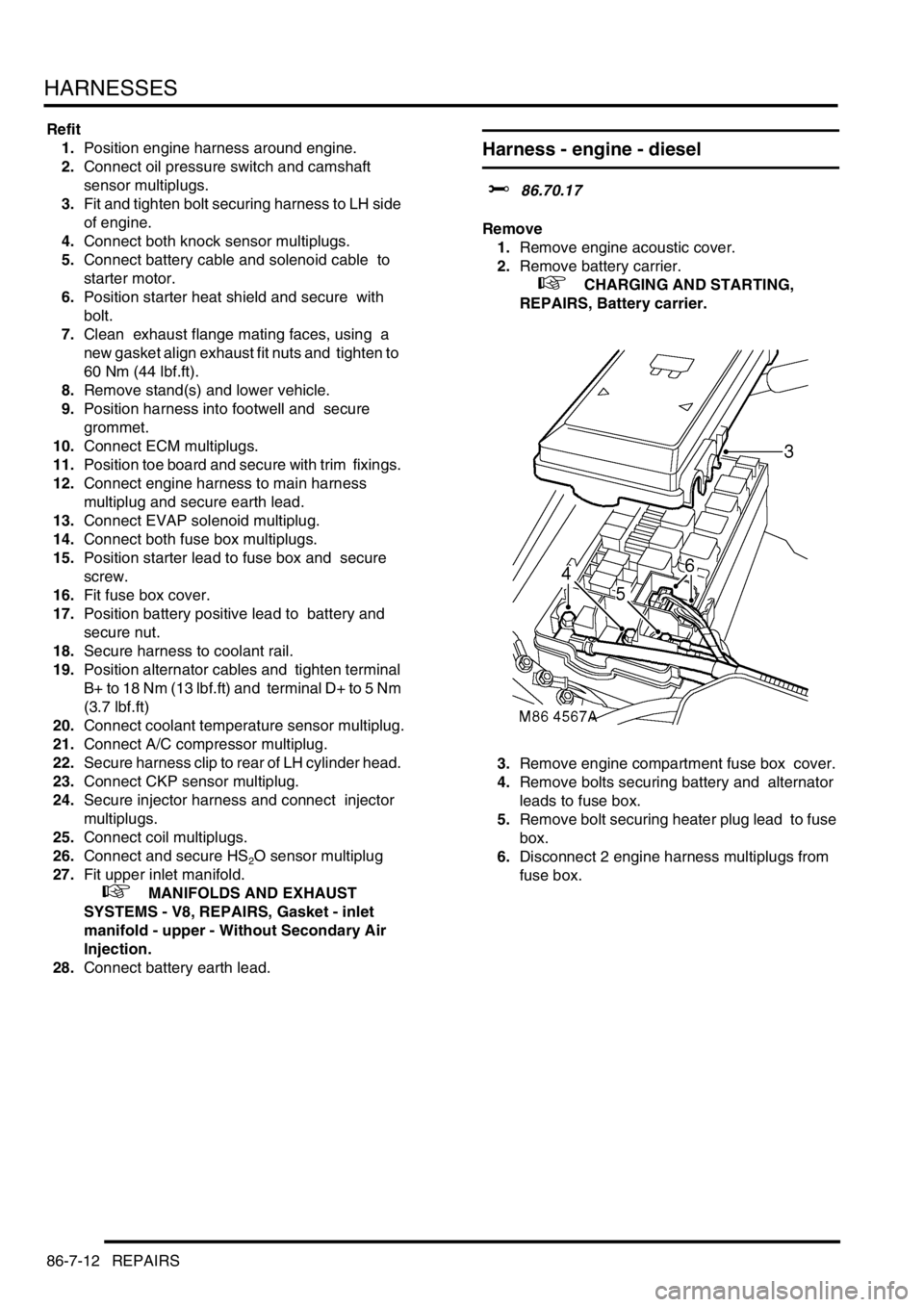
3.Remove engine compartment fuse box cover.
4.Remove bolts securing battery and alternator
leads to fuse box.
5.Remove bolt securing heater plug lead to fuse
box.
6.Disconnect 2 engine harness multiplugs from
fuse box.
Page 1420 of 1529

HARNESSES
REPAIRS 86-7-15
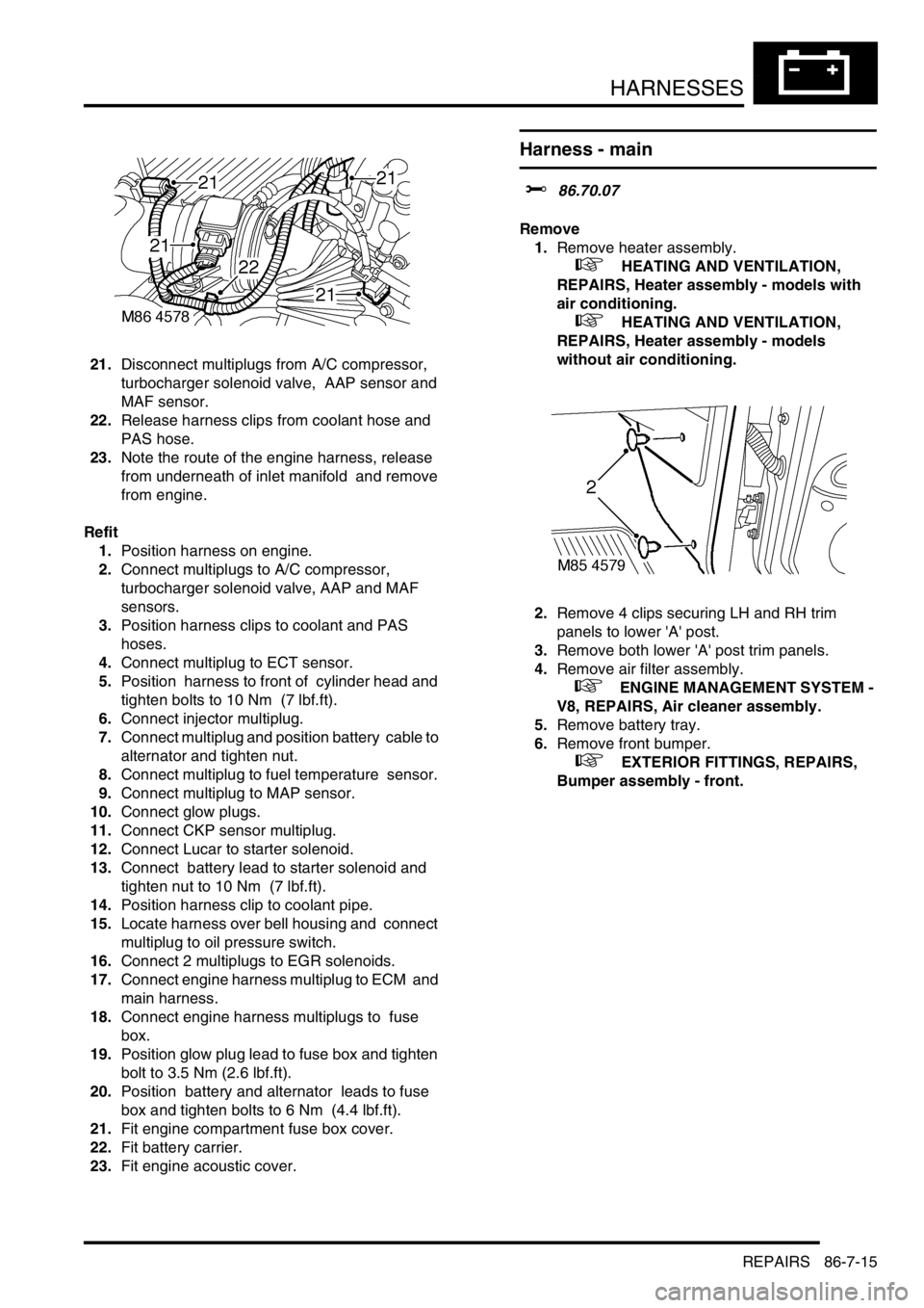
21.Disconnect multiplugs from A/C compressor,
turbocharger solenoid valve, AAP sensor and
MAF sensor.
22.Release harness clips from coolant hose and
PAS hose.
23.Note the route of the engine harness, release
from underneath of inlet manifold and remove
from engine.
Refit
1.Position harness on engine.
2.Connect multiplugs to A/C compressor,
turbocharger solenoid valve, AAP and MAF
sensors.
3.Position harness clips to coolant and PAS
hoses.
4.Connect multiplug to ECT sensor.
5.Position harness to front of cylinder head and
tighten bolts to 10 Nm (7 lbf.ft).
6.Connect injector multiplug.
7.Connect multiplug and position battery cable to
alternator and tighten nut.
8.Connect multiplug to fuel temperature sensor.
9.Connect multiplug to MAP sensor.
10.Connect glow plugs.
11.Connect CKP sensor multiplug.
12.Connect Lucar to starter solenoid.
13.Connect battery lead to starter solenoid and
tighten nut to 10 Nm (7 lbf.ft).
14.Position harness clip to coolant pipe.
15.Locate harness over bell housing and connect
multiplug to oil pressure switch.
16.Connect 2 multiplugs to EGR solenoids.
17.Connect engine harness multiplug to ECM and
main harness.
18.Connect engine harness multiplugs to fuse
box.
19.Position glow plug lead to fuse box and tighten
bolt to 3.5 Nm (2.6 lbf.ft).
20.Position battery and alternator leads to fuse
box and tighten bolts to 6 Nm (4.4 lbf.ft).
21.Fit engine compartment fuse box cover.
22.Fit battery carrier.
23.Fit engine acoustic cover.
Harness - main
$% 86.70.07
Remove
1.Remove heater assembly.
+ HEATING AND VENTILATION,
REPAIRS, Heater assembly - models with
air conditioning.
+ HEATING AND VENTILATION,
REPAIRS, Heater assembly - models
without air conditioning.
2.Remove 4 clips securing LH and RH trim
panels to lower 'A' post.
3.Remove both lower 'A' post trim panels.
4.Remove air filter assembly.
+ ENGINE MANAGEMENT SYSTEM -
V8, REPAIRS, Air cleaner assembly.
5.Remove battery tray.
6.Remove front bumper.
+ EXTERIOR FITTINGS, REPAIRS,
Bumper assembly - front.
Page 1433 of 1529

HARNESSES
86-7-28 REPAIRS
50.Feed harness through to front panel.
51.Secure fog lamp multiplug.
52.Connect headlamp level motor, headlamp and
side lamp multiplugs.
53.Fit indicator lamp.
+ LIGHTING, REPAIRS, Lamp - front
repeater - up to 03MY.
54.Secure harness to RH front panel.
55.Connect cooling fan and horn multiplug.
56.Secure harness to lower support rail.
57.Connect receiver drier and air temperature
sensor multiplugs.
58.Fit front bumper.
+ EXTERIOR FITTINGS, REPAIRS,
Bumper assembly - front.
59.Fit battery tray.
60.Fit air filter assembly.
+ ENGINE MANAGEMENT SYSTEM -
V8, REPAIRS, Air cleaner assembly.
61.Position both lower 'A' post trims and secure
with studs.
62.Fit heater assembly.
+ HEATING AND VENTILATION,
REPAIRS, Heater assembly - models with
air conditioning.
+ HEATING AND VENTILATION,
REPAIRS, Heater assembly - models
without air conditioning.
Harness - main - DVD unit
$% 86.70.25
Remove
1.Remove battery cover and disconnect the
battery earth lead.
2.Remove CD switch box.
+ IN CAR ENTERTAINMENT,
REPAIRS, Switch box - CD/DVD player.
3.Remove DVD player unit.
+ IN CAR ENTERTAINMENT,
REPAIRS, DVD screen/player unit.
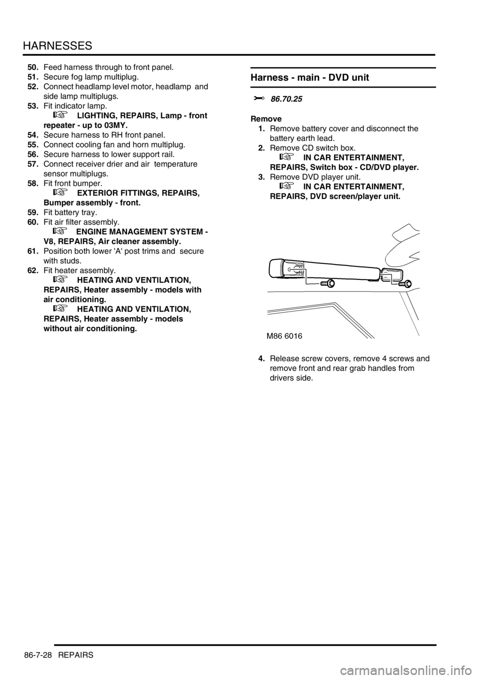
4.Release screw covers, remove 4 screws and
remove front and rear grab handles from
drivers side.