1999 LAND ROVER DISCOVERY fuse
[x] Cancel search: fusePage 1243 of 1529

WIPERS AND WASHERS
84-8 DESCRIPTION AND OPERATION
Description
General
All markets have a common wiper system with headlamp powerwash as an option.
The wipers system comprises two front wipers and one rear wiper which are powered by electric motors. A washer
reservoir is located in the front left hand wheel arch and is fitted with two electric pumps. Each pump supplies washer
fluid to either the front or rear screens. On certain models, a third pump can be fitted to operate a headlamp power
wash function. Operation of the front and rear wipers and washers is controlled by the driver using switches located
on a steering column stalk and push button switches on the fascia.
Control of the wipers and washers is achieved by the following components:
lBCU.
lIDM.
lFront wiper relay.
lFront wash/ wipe switch.
lVariable delay switch.
lFront wiper motor assembly.
lFront washer pump motor.
lRear wiper relay.
lRear wiper switch.
lRear washer switch.
lRear wiper motor.
lRear washer pump motor.
Both the Body Control Unit (BCU) and the Intelligent Driver Module (IDM) control the wiper system. The BCU controls
the time delay function of the wiper system and is located below and behind the passenger glovebox. During engine
cranking the BCU prevents wiper functions. Two relays are located in the passenger compartment fusebox. The
relays control the delay operation of the front and rear wipers. The relays are an integral part of the fusebox and
cannot be renewed separately.
Power for the wiper system is supplied by the IDM, which is integral with the passenger fusebox and cannot be
renewed as a component. A serial communication link allows communication between the IDM and the BCU.
The system has diagnostic capabilities through TestBook.
Front wipers
The two front windscreen wipers are operated by a linkage assembly and an electric motor located under the plenum
grill below the windscreen. The linkage and motor assembly is handed for left and right hand drive vehicles. The motor
is an integral part of the linkage and cannot be replaced separately.
The linkage comprises a pressed steel mounting plate which provides for the attachment of a wheel box at each end.
The mounting plate is secured to the bulkhead with flanged nuts which attach to a stud plate located behind the
bulkhead. A link arm is attached to each wheel box by a short link and secured with circlips. The link arm has an
attachment hole centrally located along its length for the electric motor drive link.
The electric motor is mounted in a recess in the bulkhead below a sealed cover plate. The drive spindle of the motor
protrudes through the cover plate and is fitted with a link. The link is attached to a tapered spline on the motor spindle
and is secured with a lock washer and nut. The opposite end of the link is attached to the central attachment point on
the link arm and secured with a circlip.
Each wheel box has a taper splined shaft which allows for the attachment of the wiper arm which is secured with a
washer and nut. The shaft of each wheel box is passed through a rubber sealed aperture in the plenum. The wiper
arm attachment to the splined shaft has a pivot to which the remainder of the arm is attached. The two parts of the
arm are connected by a spring which controls the pressure of the blade on the screen to a predetermined amount.
The wiper blades are attached to the wiper arms with a clips that allow the blade to pivot. Each wiper blade comprises
a number of levers and yokes to which the rubber wiper is attached. The levers and yokes ensure that the pressure
applied by the arm spring is distributed evenly along the full length of the blade. The rubber wiper is held in the yokes
by a pair of stainless steel strips which also contribute to the even distribution of spring pressure along the blade. The
driver's side wiper blade is fitted with an aerofoil which presses the blade onto the screen at high speed. This prevents
the blade from lifting off the screen and maintains the wiping performance.
Page 1244 of 1529

WIPERS AND WASHERS
DESCRIPTION AND OPERATION 84-9
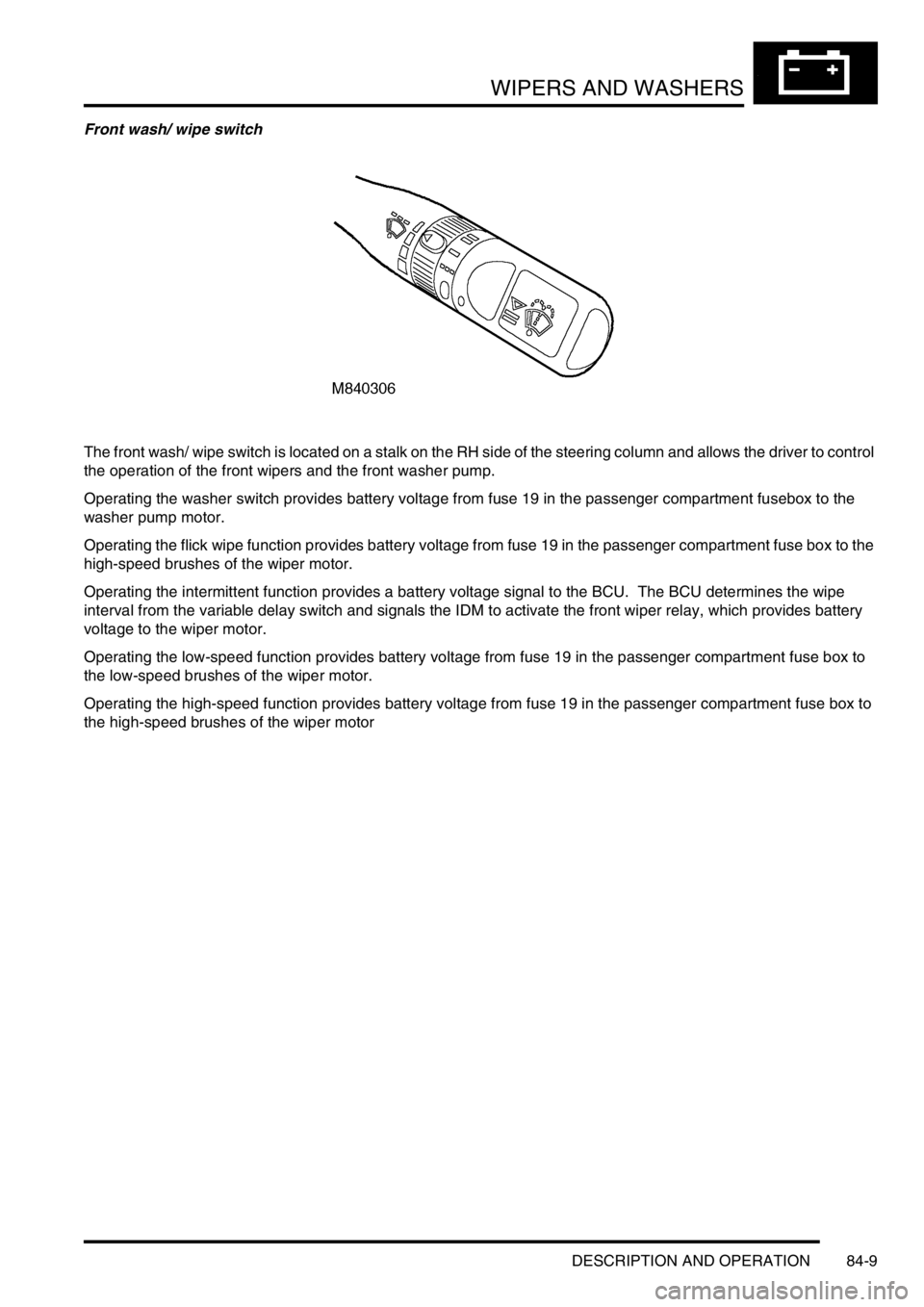
Front wash/ wipe switch
The front wash/ wipe switch is located on a stalk on the RH side of the steering column and allows the driver to control
the operation of the front wipers and the front washer pump.
Operating the washer switch provides battery voltage from fuse 19 in the passenger compartment fusebox to the
washer pump motor.
Operating the flick wipe function provides battery voltage from fuse 19 in the passenger compartment fuse box to the
high-speed brushes of the wiper motor.
Operating the intermittent function provides a battery voltage signal to the BCU. The BCU determines the wipe
interval from the variable delay switch and signals the IDM to activate the front wiper relay, which provides battery
voltage to the wiper motor.
Operating the low-speed function provides battery voltage from fuse 19 in the passenger compartment fuse box to
the low-speed brushes of the wiper motor.
Operating the high-speed function provides battery voltage from fuse 19 in the passenger compartment fuse box to
the high-speed brushes of the wiper motor
Page 1246 of 1529

WIPERS AND WASHERS
DESCRIPTION AND OPERATION 84-11
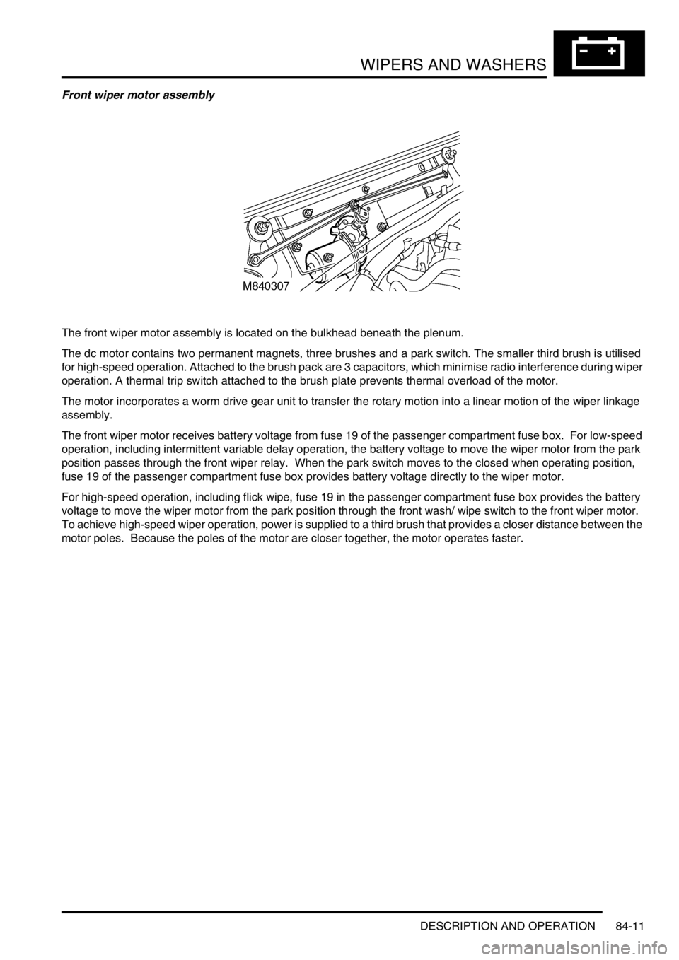
Front wiper motor assembly
The front wiper motor assembly is located on the bulkhead beneath the plenum.
The dc motor contains two permanent magnets, three brushes and a park switch. The smaller third brush is utilised
for high-speed operation. Attached to the brush pack are 3 capacitors, which minimise radio interference during wiper
operation. A thermal trip switch attached to the brush plate prevents thermal overload of the motor.
The motor incorporates a worm drive gear unit to transfer the rotary motion into a linear motion of the wiper linkage
assembly.
The front wiper motor receives battery voltage from fuse 19 of the passenger compartment fuse box. For low-speed
operation, including intermittent variable delay operation, the battery voltage to move the wiper motor from the park
position passes through the front wiper relay. When the park switch moves to the closed when operating position,
fuse 19 of the passenger compartment fuse box provides battery voltage directly to the wiper motor.
For high-speed operation, including flick wipe, fuse 19 in the passenger compartment fuse box provides the battery
voltage to move the wiper motor from the park position through the front wash/ wipe switch to the front wiper motor.
To achieve high-speed wiper operation, power is supplied to a third brush that provides a closer distance between the
motor poles. Because the poles of the motor are closer together, the motor operates faster.
Page 1249 of 1529

WIPERS AND WASHERS
84-14 DESCRIPTION AND OPERATION
Rear screen washer jet
A single washer jet for the tail door window is fitted to the rear wiper blade. The jet has four spray orifices which direct
washer fluid to either side and along the length of the wiper blade. The jet is connected by a hose from the wiper blade,
through a sealing grommet in the tail door and connects with the rear washer hose from the rear washer pump. A non-
return valve is used to join the feed hose from the pump to the washer jet hose. The non-return valve prevents fluid
draining to the reservoir and ensures that the washer operates immediately the washer pump is operated. The hose
from the pump to the tail door is located inside the main harness.
Headlamp power washer jets
When fitted, a powerwash jet for each headlamp is located in a housing on the top surface of the front bumper. The
jets are fed with fluid at high pressure from the powerwash pump. A large diameter hose connects each jet to the
pump. Each connection is secured with a metal clip to secure the hose due to the high pressure from the pump. Each
jet directs the high pressure fluid in a wide spray onto the headlamp lens.
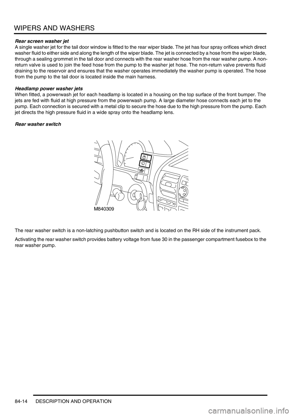
Rear washer switch
The rear washer switch is a non-latching pushbutton switch and is located on the RH side of the instrument pack.
Activating the rear washer switch provides battery voltage from fuse 30 in the passenger compartment fusebox to the
rear washer pump.
Page 1251 of 1529

WIPERS AND WASHERS
84-16 DESCRIPTION AND OPERATION
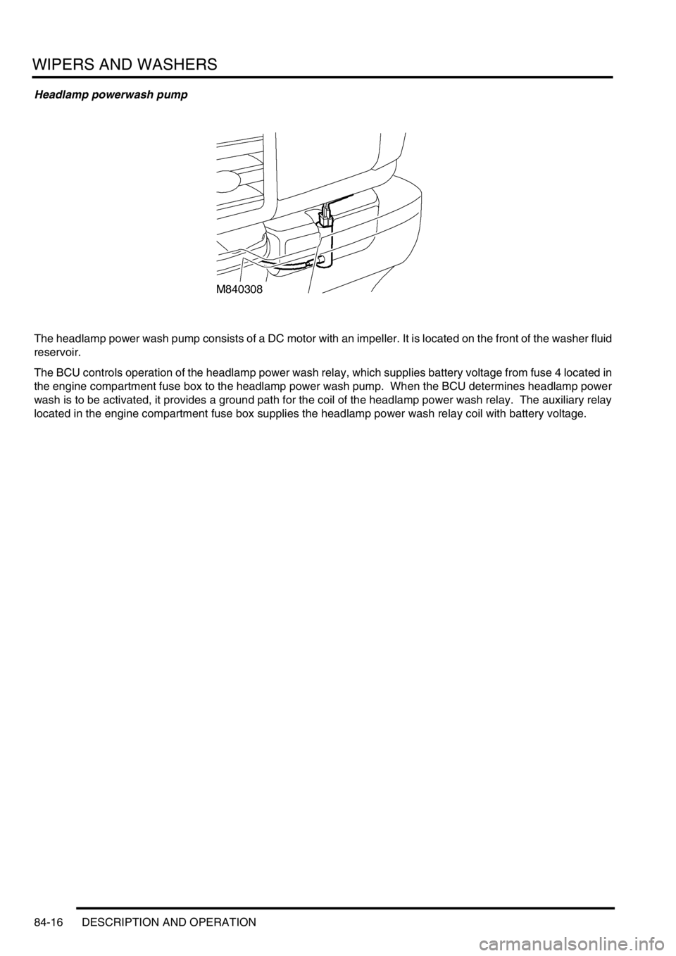
Headlamp powerwash pump
The headlamp power wash pump consists of a DC motor with an impeller. It is located on the front of the washer fluid
reservoir.
The BCU controls operation of the headlamp power wash relay, which supplies battery voltage from fuse 4 located in
the engine compartment fuse box to the headlamp power wash pump. When the BCU determines headlamp power
wash is to be activated, it provides a ground path for the coil of the headlamp power wash relay. The auxiliary relay
located in the engine compartment fuse box supplies the headlamp power wash relay coil with battery voltage.
Page 1254 of 1529

WIPERS AND WASHERS
DESCRIPTION AND OPERATION 84-19
Rear wash
Rear wash will only operate when the following conditions are met:
lIgnition switch is in position II.
lRear wash switch operated.
Operating the rear washer switch for longer than 0.4 second allows the rear washer pump motor and rear wipers to
run as long as the switch is held. The wipers run for 4 seconds after the rear washer switch is released. Flicking the
rear washer switch energises the rear washer pump motor for 0.4 second.
The rear washer operation has a higher priority than the intermittent wipe operation. If the intermittent wipe is active
when a rear washer operation is initiated, the wash cycle executes and the intermittent wipe is re-instated at the end
of the washer operation.
Wiper park switch
The park switch allows the wipers to come to rest in the park position when the wipe switch is turned off in mid-wipe.
The park switch consists of a positive and a negative contact. These two contacts are described as closed at park
and closed when operating. When the wipers first start, the park switch is in the closed at park position. A relay
controls battery voltage to the motor. Battery voltage passes through this relay contact to move the wiper motor from
the park position.
When the motor moves, the park switch moves to the closed when operating position. Battery voltage to this relay
contact is direct from fuse 19. Battery voltage passes through this contact to keep the wiper motor running. The wiper
motor operates for one complete revolution until the park switch moves to the closed at park position again.
Switching off the wipers removes battery voltage from the closed at park contact. When the wipers reach the closed
at park switch an earth is applied and the motor stops abruptly.
Headlamp power wash
Headlamp power wash activates when the following conditions are met:
lIgnition switch in position II.
lHeadlamps switched on.
lFront wash switch operated.
lBCU counter allows headlamp power wash.
Operating the front washer switch with the headlamps switched on energises the IDM, supplying a voltage to the
headlamp powerwash relay, which operates the headlamp powerwash pump and increments a counter within the
BCU. This counter prevents the headlamp powerwash pump from operating every time the front washer switch is
activated. Headlamp powerwash is only operational every third front wash cycle, providing the headlamps are on.
The counter resets when the ignition switch is turned off.
When the BCU permits headlamp power wash operation, the pump motor operates only for 0.5 second.
Page 1288 of 1529

BODY CONTROL UNIT
DESCRIPTION AND OPERATION 86-3-1
BODY CONTROL UNIT DESCRIPTION AND OPERAT ION
Description
General
The Body Control Unit (BCU) is located behind the passenger glovebox and is connected to the main harness by four
connectors on its bottom edge and an additional connector located on the side of the BCU casing. Mounting the BCU
behind the fascia makes it reasonably inaccessible for intruders to disable the anti-theft system.
The BCU uses solid-state microprocessor control to perform logical operations and timing functions for a variety of
the vehicle's electrically operated systems, these include:
lDoor locking.
lAnti-theft alarm and immobilisation system.
lExterior lighting including direction indicators and hazard warning lamps.
lCourtesy lighting.
lWipers and washers.
lElectric windows and sunroof.
lHeated windows.
The BCU also communicates with several other electronically controlled systems such as the EAT ECU and SLABS
ECU and also has a datalink between the Intelligent Driver Module (IDM) and the instrument pack. The datalink is a
low speed bus capable of transmitting and receiving messages at a data rate of 10,400 bits per second. Additional
inputs and outputs to peripheral devices are included which are necessary for determining vehicle status for particular
logical operations e.g. crank, ignition key inserted, fuel flap enable etc.
The BCU receives its power supply from the engine compartment fuse box, and is protected by a 10 A fuse.
The BCU communicates with the IDM to provide the control signals to perform power switching operations in
conjunction with dedicated relays.
IDM
The IDM is integrated into the passenger compartment fuse box, which is mounted behind the fascia below the
steering column. There are no harnesses between the fuse box and the IDM. The IDM performs the power switching
operations for several of the vehicle's electrical systems.
The IDM communicates with the BCU and the instrument pack via a serial interface. If the BCU or the IDM is replaced,
the communications link between the two units has to be re-established. This can be done either by switching on the
ignition and leaving it on for five minutes, or by using TestBook. The vehicle immobilisation will remain active until the
communications link between the BCU and IDM has been re-established.
Transit mode
To prevent excessive battery drain during transit to overseas markets, the vehicle is placed in a transit mode. The
following functions are disabled when the vehicle is in transit mode:
lVolumetric sensors.
lPassive immobilisation.
lImmobilisation of the vehicle by use of door lock.
lIgnition key interlock.
lElectric seat enable time-out with driver's door open.
Page 1289 of 1529

BODY CONTROL UNIT
86-3-2 DESCRIPTION AND OPERATION
Power supply
Battery supply to the BCU and the IDM is provided through a 10 A fuse located in the engine compartment fuse box.
The BCU unit receives an ignition switched power supply (ignition switch position II) input via a 10 A fuse in the
passenger compartment fuse box.
The BCU receives a signal when the ignition switch is turned to the crank position, it then supplies an earth path to
the starter relay coil, to enable the crank operation by supplying power through the starter relay contacts to the starter
motor.
Battery voltage is monitored and BCU operation will function normally between 8 and 18 volts. Between 5.7 and 8
volts the BCU is in the 'under volts' state. The status of the battery is used to determine which outputs may be driven.
If a voltage supply above 18 volts is experienced, outputs will not normally be driven except for those functions which
are required during cranking (robust immobilisation, antenna coil, crank enable relay and feed to gear position switch
contacts W, X, Y, Z). In the over voltage state the vehicle can be driven, but all other functions are disabled and
outputs are switched off (power windows, heated screen, direction indicators etc.).
All functions are disabled on power up until communications between the BCU and IDM have been established. If
communications cannot be established, operation will commence with degraded functionality.
Battery supply to the IDM is provided through the inertia switch and a 10 A fuse in the engine compartment fuse box.
If the inertia switch contacts are closed battery voltage is available at the IDM; if the inertia switch contacts are open
there is no battery supply to the IDM. The supply condition of the IDM is signalled to the BCU via the serial bus. If the
inertia switch is operated (contacts open) the change in state is detected by the BCU which unlocks the doors if the
ignition switch is in position II and the alarm is not set.
The BCU is earthed through a hard-wire connection.
Inputs and outputs
The BCU and IDM process inputs and provide the necessary outputs for control and operation of the vehicle's 'body'
systems.
BCU inputs
The BCU processes signals received from the following components:
lDoor latch switches.
lDriver's door key lock/ unlock switches.
lBonnet activated security system.
lVolumetric sensors.
lCentral Door Locking (CDL) switches.
lRemote transmitter (via receiver unit).
lInertia fuel cut-off switch.
lIgnition switch.
lFuel flap release switch.
The input voltages (V
in) for BCU digital signals are defined as follows:
lLogic 1 when V
in ≥ 6V.
lLogic 0 when V
in ≤ 2V.
BCU input voltages between 2 and 6 volts are indeterminate and cannot be guaranteed.
Analogue input voltages are measured as a ratio with respect to battery voltage.