1999 LAND ROVER DISCOVERY lumbar support
[x] Cancel search: lumbar supportPage 23 of 1529

CONTENTS
20 CONTENTS
SCREENS ................................................................................................. 76-4-1
REPAIRS
Glass/sealing rubber - tail door ..................................................................................................... 76-4-1
Windscreen ................................................................................................................................... 76-4-2
Glass - body side - rear ................................................................................................................ 76-4-4
Glass - alpine light ........................................................................................................................ 76-4-6
SEATS ....................................................................................................... 76-5-1
DESCRIPTION AND OPERATION
Electric seat component location .................................................................................................... 76-5-1
Electric seat block diagram ............................................................................................................. 76-5-2
Description - electric seats.............................................................................................................. 76-5-4
Operation - electric seats ................................................................................................................ 76-5-8
DESCRIPTION AND OPERATION
Heated seat component location .................................................................................................... 76-5-9
Heated seat block diagram (electric seats).................................................................................... 76-5-10
Description - heated seats .............................................................................................................. 76-5-11
Operation - heated seats ................................................................................................................ 76-5-13
REPAIRS
Seat - front ..................................................................................................................................... 76-5-15
Seat - third row ............................................................................................................................... 76-5-16
Seat - rear ....................................................................................................................................... 76-5-18
Bolster assembly - rear armrest ..................................................................................................... 76-5-19
Cover - cushion - front seat .......................................................................................................... 76-5-20
Heating element - cushion - front seat .......................................................................................... 76-5-21
Cover - cushion - rear seat ........................................................................................................... 76-5-22
Bladder - lumbar support .............................................................................................................. 76-5-23
Motor - fore and aft - front seat ..................................................................................................... 76-5-23
Motor - rise and fall - front seat ..................................................................................................... 76-5-24
Motor - tilt - front seat .................................................................................................................... 76-5-24
Motor - recline ................................................................................................................................. 76-5-25
Switch - electric seats .................................................................................................................... 76-5-25
Cable - rear squab latch ............................................................................................................... 76-5-26
Latch - rear seat ........................................................................................................................... 76-5-26
Cover - squab - front seat ............................................................................................................. 76-5-28
Cover - squab - RH rear seat ........................................................................................................ 76-5-31
Heating element - squab - front seat ............................................................................................ 76-5-33
Head restraint - third row seat ....................................................................................................... 76-5-33
Page 998 of 1529

SEATS
DESCRIPTION AND OPERATION 76-5-1
SEATS DESCRIPTION AND OPERAT ION
Electric seat component location
RHD shown, LHD similar
1BCU
2Drivers door switch
3Power relay
4Satellite fuse box
5Switch pack
6Fore/aft motor7Cushion front up/down motor
8Cushion rear up/down motor
9Squab fore/aft motor
10Lumbar support bladder
11Lumbar pump
Page 1001 of 1529

SEATS
76-5-4 DESCRIPTION AND OPERATION
Description - electric seats
General
All markets use the same electric seat system. Electically operated lumbar support is optional. The system consists
of an electrical sub-system and a mechanical sub-system.
The electrical sub-system consists of the following components:
lBCU.
lSeat power relays.
lSeat switch packs.
lSeat fore/ aft motors.
lSeat cushion front up/ down motors.
lSeat cushion rear up/ down motors.
lSeat squab motor.
lLumbar pump.
lLumbar deflate solenoid.
The mechanical sub-system consist of the following components:
lGear wheels.
lRack and pinion assemblies.
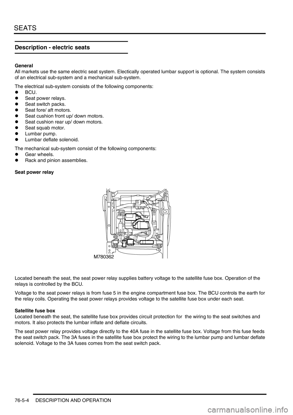
Seat power relay
Located beneath the seat, the seat power relay supplies battery voltage to the satellite fuse box. Operation of the
relays is controlled by the BCU.
Voltage to the seat power relays is from fuse 5 in the engine compartment fuse box. The BCU controls the earth for
the relay coils. Operating the seat power relays provides voltage to the satellite fuse box under each seat.
Satellite fuse box
Located beneath the seat, the satellite fuse box provides circuit protection for the wiring to the seat switches and
motors. It also protects the lumbar inflate and deflate circuits.
The seat power relay provides voltage directly to the 40A fuse in the satellite fuse box. Voltage from this fuse feeds
the seat switch pack. The 3A fuses in the satellite fuse box protect the wiring to the lumbar pump and lumbar deflate
solenoid. Voltage to the 3A fuses comes from the seat switch pack.
Page 1004 of 1529

SEATS
DESCRIPTION AND OPERATION 76-5-7
Lumbar pump
The lumbar pump inflates a bladder in the squab which provides extra support for the seat occupant. With no load on
the seat it takes approximately 10 seconds to completely inflate the bladder. With a load of 25 kg (55 lb) it takes
approximately 15 seconds to inflate the bladder. A pressure cut off switch in the system will operate at 0.12 to 1.93
bar (1.8 to 28 lbf.in
2). If a problem occurs with the lumbar bladder, e.g. a rupture, the whole lumbar system must be
replaced. The components are not serviceable.
Power comes from the seat switch pack through a 3A fuse in the satellite fuse box. The lumbar pump and the lumbar
deflate solenoid share an earth.
Lumbar deflate solenoid
The lumbar deflate solenoid vents the lumbar bladder to atmosphere to allow air to evacuate the bladder. The average
time to evacuate the bladder with a load of 25 kg (55 lb) is 9 seconds.
Power comes from the seat switch pack through a 3A fuse in the satellite fuse box. The lumbar deflate solenoid and
the lumbar pump share an earth.
Page 1005 of 1529

SEATS
76-5-8 DESCRIPTION AND OPERATION
Operation - electric seats
Seat power relay enable line
The BCU provides the seat power relays with an earth supply to the relay coil that enables the relay operation. When
this seat power relay enable line is active, the seat power relay energises allowing seat operation.
In order for the seat power relay to be active the BCU must detect either of the following condition options:
lIgnition switch in position II.
lIgnition switch in position II or driver's door within 45 seconds of opening.
Seat fore/ aft movement
When the cushion switch is operated and the seat power relay enable line is operating, power and earth are supplied
to the motor in the seat, allowing the seat to move forward or backward depending on switch position. The motor
drives a gear wheel along a gear rack connected to the seat base. Sliding the cushion switch forward causes the motor
to drive the seat forward. Sliding the cushion switch rearward reverses polarity of the voltage at the seat motor, driving
the seat rearward.
Seat cushion front up/ down movement
When the cushion switch is operated and the seat power relay enable line is operating, power and earth are supplied
to the motor in the seat, allowing the front of the seat cushion to move upward or downward depending on switch
position. The motor drives a gear wheel along a gear rack connected to the seat base. Sliding the front of the cushion
switch upward causes the motor to drive the seat upward. Sliding the front of the cushion switch downward reverses
polarity of the voltage at the seat motor driving the seat downward.
Seat cushion rear up/ down movement
When the cushion switch is operated and the seat power relay enable line is operating, power and earth are supplied
to the motor in the seat, allowing the seat to move upwards or downwards depending on switch position. The motor
drives a gear wheel along a gear rack connected to the seat base. Sliding the rear of the cushion switch upward
causes the motor to drive the seat upward. Sliding the rear of the cushion switch downward reverses polarity of the
voltage at the seat motor driving the seat downward.
Squab fore/ aft movement
When the squab switch is operated and the seat power relay enable line is operating, power and earth is supplied to
the motor in the squab, allowing the squab to move forward or backward depending on switch position. The motor
drives a gear wheel along a rotary gear rack connected to the squab. Sliding the squab switch forward causes the
motor to drive the squab forward. Sliding the squab switch rearward reverses polarity of the voltage at the seat motor
driving the squab rearward.
Lumbar inflate/ deflate
Sliding the squab switch upwards when the seat power relay enable line is operating applies voltage to the lumbar
pump. The lumbar pump inflates the lumbar bladder, increasing lumbar support. The lumbar pump and the normally
closed lumbar deflate solenoid hold the air in the bladder. Sliding the squab switch downwards applies voltage to the
deflate solenoid, venting the air in the lumbar bladder to atmosphere, decreasing lumbar support.
Diagnostics
TestBook can only verify that the seat power relay line is enabled. It cannot determine the status of the system or any
of the components.
Page 1020 of 1529

SEATS
REPAIRS 76-5-23
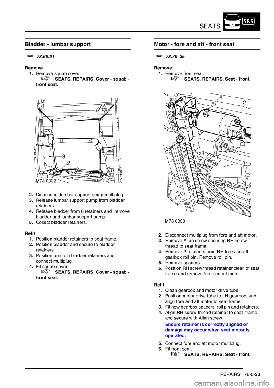
Bladder - lumbar support
$% 78.60.01
Remove
1.Remove squab cover.
+ SEATS, REPAIRS, Cover - squab -
front seat.
2.Disconnect lumbar support pump multiplug.
3.Release lumbar support pump from bladder
retainers.
4.Release bladder from 8 retainers and remove
bladder and lumbar support pump.
5.Collect bladder retainers.
Refit
1.Position bladder retainers to seat frame.
2.Position bladder and secure to bladder
retainers
3.Position pump in bladder retainers and
connect multiplug.
4.Fit squab cover.
+ SEATS, REPAIRS, Cover - squab -
front seat.
Motor - fore and aft - front seat
$% 78.70 25
Remove
1.Remove front seat.
+ SEATS, REPAIRS, Seat - front.
2.Disconnect multiplug from fore and aft motor.
3.Remove Allen screw securing RH screw
thread to seat frame.
4.Remove 2 retainers from RH fore and aft
gearbox roll pin. Remove roll pin.
5.Remove spacers.
6.Position RH screw thread retainer clear of seat
frame and remove fore and aft motor.
Refit
1.Clean gearbox and motor drive tube.
2.Position motor drive tube to LH gearbox and
align fore and aft motor to seat frame.
3.Fit new gearbox spacers, roll pin and retainers.
4.Align RH screw thread retainer to seat frame
and secure with Allen screw.
Ensure retainer is correctly aligned or
damage may occur when seat motor is
operated.
5.Connect fore and aft motor multiplug.
6.Fit front seat.
+ SEATS, REPAIRS, Seat - front.