Page 1035 of 1529
SUNROOF
76-6-4 DESCRIPTION AND OPERATION
System block diagram
1Passenger compartment fuse box
2BCU
3Sunroof ECU
4Front sunroof switch
5Front sunroof motor and microswitch6Rear sunroof - front switch
7Rear sunroof isolation switch
8Rear sunroof - rear switch
9Rear sunroof motor and microswitch
Page 1096 of 1529
PANEL REPAIRS
REPAIRS 77-2-29
Refit
1. Models with A/C: Fit A/C pipes and recharge
A/C system.
+ AIR CONDITIONING, REFRIGERANT
RECOVERY, RECYCLING AND
RECHARGING, Refrigerant recovery,
recycling and recharging.
2.Fit harness to valance.
3.Fit brake pipes to valance.
4.Fit ABS modulator.
+ BRAKES, REPAIRS, Modulator unit
- ABS.
5.Fit PAS/ACE reservoir, refill fluids to correct
levelsand bleed ACE system.
+ FRONT SUSPENSION,
ADJUSTMENTS, ACE hydraulic system
bleeding.
+ CAPACITIES, FLUIDS,
LUBRICANTS AND SEALANTS, Fluids.
6.Fit air filter assembly.
+ ENGINE MANAGEMENT SYSTEM -
V8, REPAIRS, Air cleaner assembly.
+ ENGINE MANAGEMENT SYSTEM -
Td5, REPAIRS, Air filter assembly.
7.Fit front wing.
+ EXTERIOR FITTINGS, REPAIRS,
Wing - front - up to 03MY.
+ EXTERIOR FITTINGS, REPAIRS,
Wing - front - from 03MY.
8.Connect leads/multiplug to alternator.
9.Connect battery leads, negative lead last.
Valance upper assembly - RH
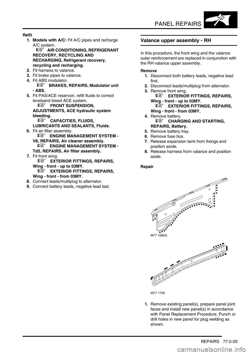
In this procedure, the front wing and the valance
outer reinforcement are replaced in conjunction with
the RH valance upper assembly.
Remove
1.Disconnect both battery leads, negative lead
first.
2.Disconnect leads/multiplug from alternator.
3.Remove front wing.
+ EXTERIOR FITTINGS, REPAIRS,
Wing - front - up to 03MY.
+ EXTERIOR FITTINGS, REPAIRS,
Wing - front - from 03MY.
4.Remove battery.
+ CHARGING AND STARTING,
REPAIRS, Battery.
5.Remove battery tray.
6.Remove fuse box.
7.Release expansion tank from fixings and
position aside.
8.Release harness from valance and position
aside.
Repair
1.Remove existing panel(s), prepare panel joint
faces and install new panel(s) in accordance
with Panel Replacement Procedure. Punch or
drill holes in new panel for plug welding as
shown.
M77 1692A
M77 1750
Page 1097 of 1529
PANEL REPAIRS
77-2-30 REPAIRS
Refit
1.Fit harness to valance.
2.Fit and secure expansion tank to fixings.
3.Fit fuse box.
4.Fit battery tray.
5.Fit battery.
+ CHARGING AND STARTING,
REPAIRS, Battery.
6.Fit front wing.
+ EXTERIOR FITTINGS, REPAIRS,
Wing - front - up to 03MY.
+ EXTERIOR FITTINGS, REPAIRS,
Wing - front - from 03MY.
7.Connect leads/multiplug to alternator.
8.Connect battery leads, negative lead last.
Valance upper assembly (front section) -
LH
In this procedure, the front wing, the valance outer
reinforcement (front section) and the bonnet alarm
switch mounting bracket are replaced in conjunction
with the LH valance upper assembly (front section).
Remove
1.Disconnect both battery leads, negative lead
first.
2.Disconnect leads/multiplug from alternator.
3.Remove front wing.
+ EXTERIOR FITTINGS, REPAIRS,
Wing - front - up to 03MY.
+ EXTERIOR FITTINGS, REPAIRS,
Wing - front - from 03MY.
4.Remove air filter assembly.
+ ENGINE MANAGEMENT SYSTEM -
Td5, REPAIRS, Air filter assembly.
+ ENGINE MANAGEMENT SYSTEM -
V8, REPAIRS, Air cleaner assembly.
5.Remove PAS/ACE reservoir.
6.Remove ABS modulator.
+ BRAKES, REPAIRS, Modulator unit
- ABS.
7.Release harness from valance and position
aside.
8. Models with A/C: Depressurise A/C system
and remove pipes from valance.
+ AIR CONDITIONING, REFRIGERANT
RECOVERY, RECYCLING AND
RECHARGING, Refrigerant recovery,
recycling and recharging.
Page 1099 of 1529
PANEL REPAIRS
77-2-32 REPAIRS
Valance upper assembly (front section) -
RH
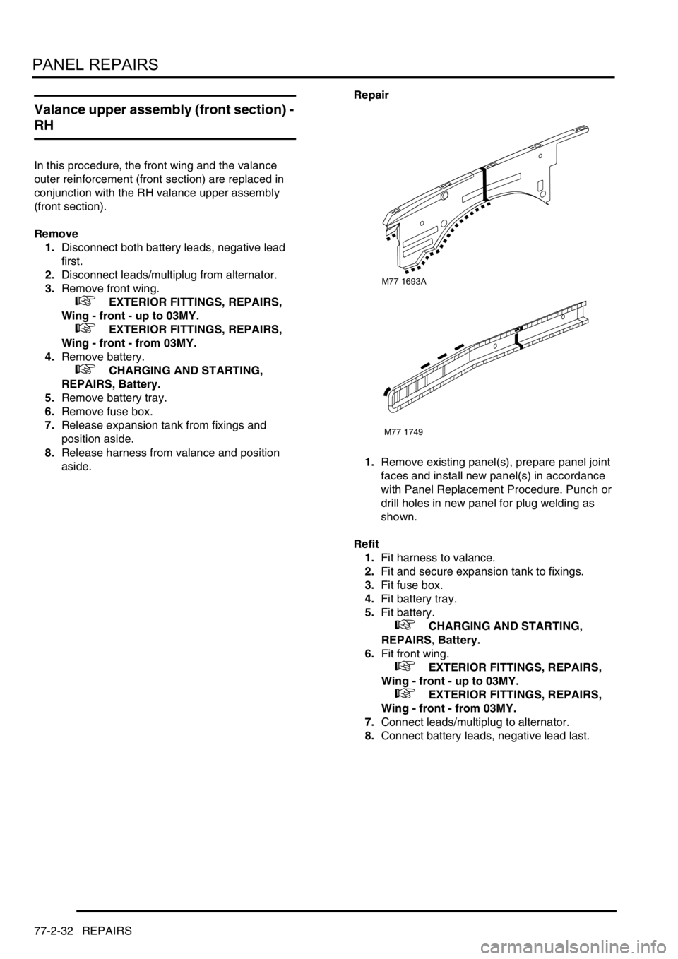
In this procedure, the front wing and the valance
outer reinforcement (front section) are replaced in
conjunction with the RH valance upper assembly
(front section).
Remove
1.Disconnect both battery leads, negative lead
first.
2.Disconnect leads/multiplug from alternator.
3.Remove front wing.
+ EXTERIOR FITTINGS, REPAIRS,
Wing - front - up to 03MY.
+ EXTERIOR FITTINGS, REPAIRS,
Wing - front - from 03MY.
4.Remove battery.
+ CHARGING AND STARTING,
REPAIRS, Battery.
5.Remove battery tray.
6.Remove fuse box.
7.Release expansion tank from fixings and
position aside.
8.Release harness from valance and position
aside.Repair
1.Remove existing panel(s), prepare panel joint
faces and install new panel(s) in accordance
with Panel Replacement Procedure. Punch or
drill holes in new panel for plug welding as
shown.
Refit
1.Fit harness to valance.
2.Fit and secure expansion tank to fixings.
3.Fit fuse box.
4.Fit battery tray.
5.Fit battery.
+ CHARGING AND STARTING,
REPAIRS, Battery.
6.Fit front wing.
+ EXTERIOR FITTINGS, REPAIRS,
Wing - front - up to 03MY.
+ EXTERIOR FITTINGS, REPAIRS,
Wing - front - from 03MY.
7.Connect leads/multiplug to alternator.
8.Connect battery leads, negative lead last.
M77 1693A
M77 1749
Page 1100 of 1529
PANEL REPAIRS
REPAIRS 77-2-33
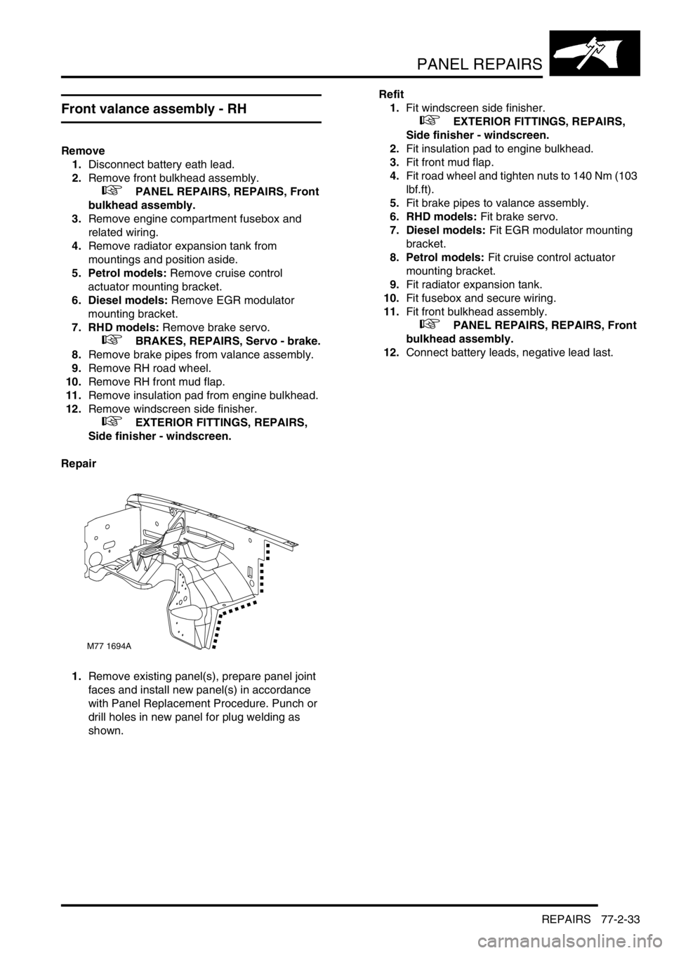
Front valance assembly - RH
Remove
1.Disconnect battery eath lead.
2.Remove front bulkhead assembly.
+ PANEL REPAIRS, REPAIRS, Front
bulkhead assembly.
3.Remove engine compartment fusebox and
related wiring.
4.Remove radiator expansion tank from
mountings and position aside.
5. Petrol models: Remove cruise control
actuator mounting bracket.
6. Diesel models: Remove EGR modulator
mounting bracket.
7. RHD models: Remove brake servo.
+ BRAKES, REPAIRS, Servo - brake.
8.Remove brake pipes from valance assembly.
9.Remove RH road wheel.
10.Remove RH front mud flap.
11.Remove insulation pad from engine bulkhead.
12.Remove windscreen side finisher.
+ EXTERIOR FITTINGS, REPAIRS,
Side finisher - windscreen.
Repair
1.Remove existing panel(s), prepare panel joint
faces and install new panel(s) in accordance
with Panel Replacement Procedure. Punch or
drill holes in new panel for plug welding as
shown.Refit
1.Fit windscreen side finisher.
+ EXTERIOR FITTINGS, REPAIRS,
Side finisher - windscreen.
2.Fit insulation pad to engine bulkhead.
3.Fit front mud flap.
4.Fit road wheel and tighten nuts to 140 Nm (103
lbf.ft).
5.Fit brake pipes to valance assembly.
6. RHD models: Fit brake servo.
7. Diesel models: Fit EGR modulator mounting
bracket.
8. Petrol models: Fit cruise control actuator
mounting bracket.
9.Fit radiator expansion tank.
10.Fit fusebox and secure wiring.
11.Fit front bulkhead assembly.
+ PANEL REPAIRS, REPAIRS, Front
bulkhead assembly.
12.Connect battery leads, negative lead last.
M77 1694A
Page 1172 of 1529
HEATING AND VENTILATION
REPAIRS 80-15
REPAIRS
Heater control and fan switch
$% 80.10.02
Remove
1.Remove louvre panel assembly.
+ INTERIOR TRIM COMPONENTS,
REPAIRS, Louvre panel assembly - centre
fascia.
2.Release temperature and air distribution cable
abutments from heater control housing and
disconnect inner cables from controls.
3.Disconnect multiplugs from switches.
4.Disconnect multiplug from control illumination.
5.Remove heater control.
6.Remove 3 switches from heater control.
Refit
1.Fit switches to heater control housing.
2.Position heater control assembly and connect
multiplugs to switches and illumination.
3.Connect heater control cables and secure
outer cable abutments to casing.
4.Fit louvre panel assembly.
+ INTERIOR TRIM COMPONENTS,
REPAIRS, Louvre panel assembly - centre
fascia.
Cables - heater control
$% 80.10.06
Remove
1. Driver temperature control and air flow
control cables:Release fixings and lower
fascia fuse box access cover.
Page 1173 of 1529
HEATING AND VENTILATION
80-16REPAIRS
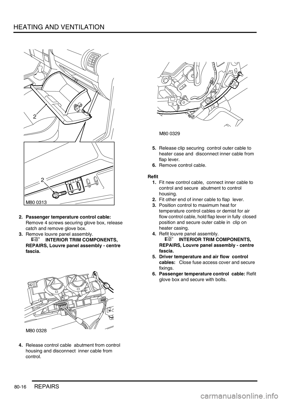
2. Passenger temperature control cable:
Remove 4 screws securing glove box, release
catch and remove glove box.
3.Remove louvre panel assembly.
+ INTERIOR TRIM COMPONENTS,
REPAIRS, Louvre panel assembly - centre
fascia.
4.Release control cable abutment from control
housing and disconnect inner cable from
control. 5.Release clip securing control outer cable to
heater case and disconnect inner cable from
flap lever.
6.Remove control cable.
Refit
1.Fit new control cable, connect inner cable to
control and secure abutment to control
housing.
2.Fit other end of inner cable to flap lever.
3.Position control to maximum heat for
temperature control cables or demist for air
flow control cable, hold flap lever in fully closed
position and secure outer cable in clip on
heater casing.
4.Refit louvre panel assembly.
+ INTERIOR TRIM COMPONENTS,
REPAIRS, Louvre panel assembly - centre
fascia.
5. Driver temperature and air flow control
cables: Close fuse access cover and secure
fixings.
6. Passenger temperature control cable: Refit
glove box and secure with bolts.
Page 1236 of 1529
WIPERS AND WASHERS
DESCRIPTION AND OPERATION 84-1
WIPERS AND WASHERS DESCRIPTION AND OPERAT ION
Wipers and washers component layout
RHD shown, LHD similar
1Headlamp power wash relay
2Passenger compartment fuse box
(rear wiper relay, front wiper relay and IDM)
3Variable Delay Switch
4Front wash/ wipe switch
5Rear wiper motor
6Rear washer switch7Rear wiper switch
8Body Control Unit (BCU)
9Front washer pump
10Rear washer pump
11Front wiper motor assembly
12Headlamp power wash pump