1999 LAND ROVER DISCOVERY radio
[x] Cancel search: radioPage 1248 of 1529
WIPERS AND WASHERS
DESCRIPTION AND OPERATION 84-13
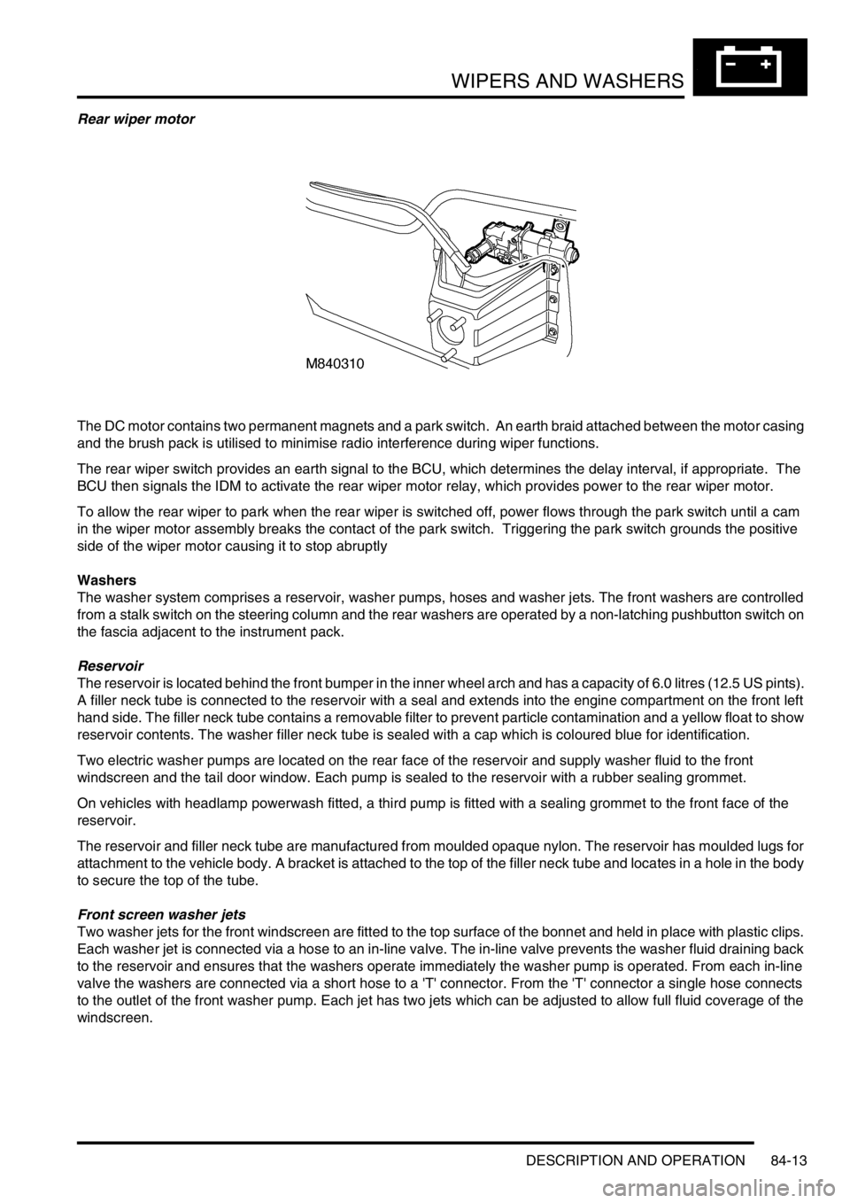
Rear wiper motor
The DC motor contains two permanent magnets and a park switch. An earth braid attached between the motor casing
and the brush pack is utilised to minimise radio interference during wiper functions.
The rear wiper switch provides an earth signal to the BCU, which determines the delay interval, if appropriate. The
BCU then signals the IDM to activate the rear wiper motor relay, which provides power to the rear wiper motor.
To allow the rear wiper to park when the rear wiper is switched off, power flows through the park switch until a cam
in the wiper motor assembly breaks the contact of the park switch. Triggering the park switch grounds the positive
side of the wiper motor causing it to stop abruptly
Washers
The washer system comprises a reservoir, washer pumps, hoses and washer jets. The front washers are controlled
from a stalk switch on the steering column and the rear washers are operated by a non-latching pushbutton switch on
the fascia adjacent to the instrument pack.
Reservoir
The reservoir is located behind the front bumper in the inner wheel arch and has a capacity of 6.0 litres (12.5 US pints).
A filler neck tube is connected to the reservoir with a seal and extends into the engine compartment on the front left
hand side. The filler neck tube contains a removable filter to prevent particle contamination and a yellow float to show
reservoir contents. The washer filler neck tube is sealed with a cap which is coloured blue for identification.
Two electric washer pumps are located on the rear face of the reservoir and supply washer fluid to the front
windscreen and the tail door window. Each pump is sealed to the reservoir with a rubber sealing grommet.
On vehicles with headlamp powerwash fitted, a third pump is fitted with a sealing grommet to the front face of the
reservoir.
The reservoir and filler neck tube are manufactured from moulded opaque nylon. The reservoir has moulded lugs for
attachment to the vehicle body. A bracket is attached to the top of the filler neck tube and locates in a hole in the body
to secure the top of the tube.
Front screen washer jets
Two washer jets for the front windscreen are fitted to the top surface of the bonnet and held in place with plastic clips.
Each washer jet is connected via a hose to an in-line valve. The in-line valve prevents the washer fluid draining back
to the reservoir and ensures that the washers operate immediately the washer pump is operated. From each in-line
valve the washers are connected via a short hose to a 'T' connector. From the 'T' connector a single hose connects
to the outlet of the front washer pump. Each jet has two jets which can be adjusted to allow full fluid coverage of the
windscreen.
Page 1328 of 1529
ALARM SYSTEM AND HORN
DESCRIPTION AND OPERATION 86-4-5
Description
General
The anti-theft system deters the theft of the vehicle with both active and passive systems. The active systems monitor
the vehicle perimeter and, in some markets the vehicle interior, for intrusion. If the system detects intrusion, an alarm
sounds. The passive systems include a vehicle immobiliser as well as protection against intrusion through super
locking the doors. The vehicle is immobilised whenever the ignition key is removed from the ignition switch. Super
locking prevents the interior door handles from opening the doors. In addition, there are many features and functions
that enhance system operation.
It is possible to perform the various functions associated with the anti-theft system remotely. To accomplish this, the
handset generates a radio frequency when the lock button or unlock button is depressed. This signal is transmitted
to the Body Control Unit (BCU) via a receiver located in front of rear sunroof beneath the headlining. Precise alignment
of the handset to the receiver is not necessary. The approximate operating range between the handset and the
receiver is 10 metres (33 feet).
It is important to understand the configuration of the system on each particular vehicle. There are many
different combinations of features with dedicated operating modes. System configuration for each vehicle
can be determined using TestBook.
The anti-theft system is controlled centrally by the BCU, which is located below and behind the passenger glovebox.
A serial communication link communicates between the Intelligent Driver Module (IDM) located within the fusebox,
the BCU and the LED located in the instrument panel.
The state of the alarm is stored in the BCU. If the battery is disconnected while the alarm is armed, the alarm will be
triggered when the battery is reconnected.
NOTE: Disconnecting the battery while the alarm is armed triggers the alarm. Always disarm the alarm system before
disconnecting the battery.
The BCU also receives inputs from the following components:
lIgnition key in sensor.
lIgnition switch.
lFuel cut off switch.
lFuel flap release switch.
The BCU also interacts with the following components:
lStarter relay.
lVehicle horns.
lDirection indicators.
lFuel flap release actuator.
lCourtesy lamps.
Page 1335 of 1529
ALARM SYSTEM AND HORN
86-4-12 DESCRIPTION AND OPERATION
Handset and receiver
The handset is incorporated in the key. It uses coded radio frequency signals to lock, unlock and super lock the vehicle
remotely with a range of up to 10 metres (33 ft). The handset also mobilises the vehicle by transmitting a
remobilisation signal when the handset is within range of the passive remobilisation exciter coil.
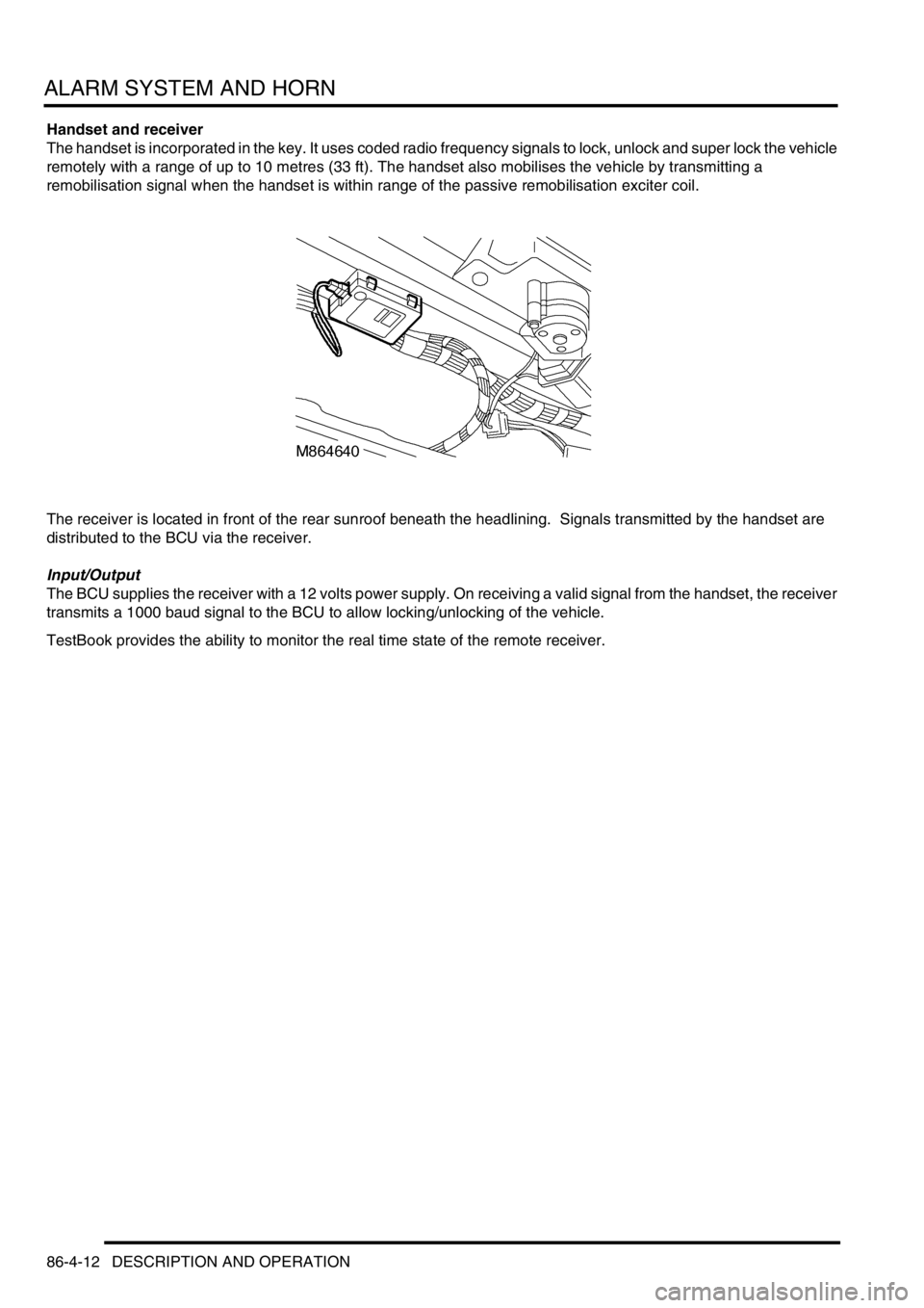
The receiver is located in front of the rear sunroof beneath the headlining. Signals transmitted by the handset are
distributed to the BCU via the receiver.
Input/Output
The BCU supplies the receiver with a 12 volts power supply. On receiving a valid signal from the handset, the receiver
transmits a 1000 baud signal to the BCU to allow locking/unlocking of the vehicle.
TestBook provides the ability to monitor the real time state of the remote receiver.
Page 1368 of 1529
IN CAR ENTERTAINMENT
DESCRIPTION AND OPERATION 86-6-1
IN CAR ENTERTA INMENT DESCRIPTION AND OPERAT ION
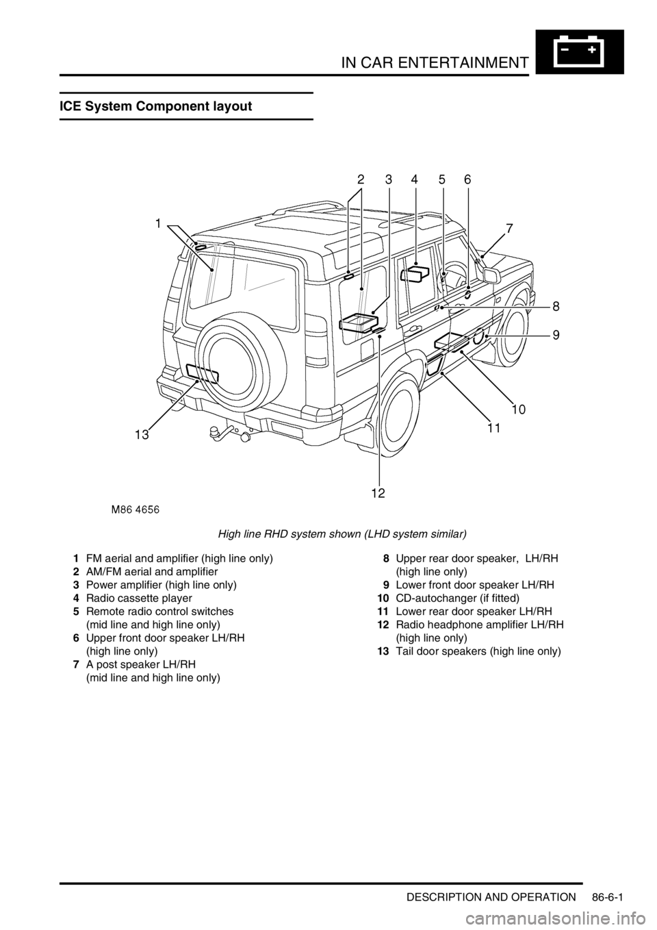
ICE System Component layout
High line RHD system shown (LHD system similar)
1FM aerial and amplifier (high line only)
2AM/FM aerial and amplifier
3Power amplifier (high line only)
4Radio cassette player
5Remote radio control switches
(mid line and high line only)
6Upper front door speaker LH/RH
(high line only)
7A post speaker LH/RH
(mid line and high line only)8Upper rear door speaker, LH/RH
(high line only)
9Lower front door speaker LH/RH
10CD-autochanger (if fitted)
11Lower rear door speaker LH/RH
12Radio headphone amplifier LH/RH
(high line only)
13Tail door speakers (high line only)
Page 1369 of 1529
IN CAR ENTERTAINMENT
86-6-2 DESCRIPTION AND OPERATION
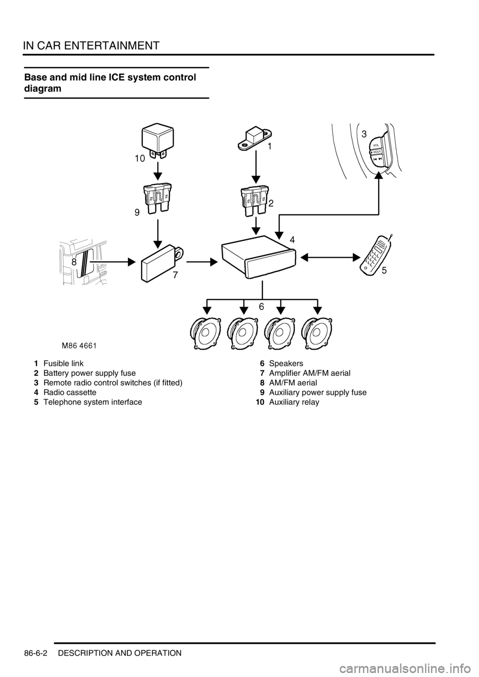
Base and mid line ICE system control
diagram
1Fusible link
2Battery power supply fuse
3Remote radio control switches (if fitted)
4Radio cassette
5Telephone system interface6Speakers
7Amplifier AM/FM aerial
8AM/FM aerial
9Auxiliary power supply fuse
10Auxiliary relay
Page 1370 of 1529
IN CAR ENTERTAINMENT
DESCRIPTION AND OPERATION 86-6-3
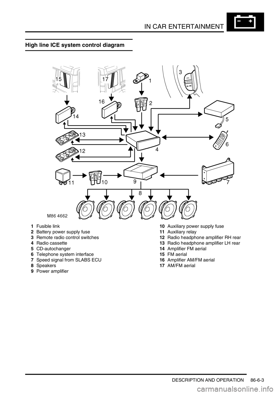
High line ICE system control diagram
1Fusible link
2Battery power supply fuse
3Remote radio control switches
4Radio cassette
5CD-autochanger
6Telephone system interface
7Speed signal from SLABS ECU
8Speakers
9Power amplifier10Auxiliary power supply fuse
11Auxiliary relay
12Radio headphone amplifier RH rear
13Radio headphone amplifier LH rear
14Amplifier FM aerial
15FM aerial
16Amplifier AM/FM aerial
17AM/FM aerial
Page 1371 of 1529

IN CAR ENTERTAINMENT
86-6-4 DESCRIPTION AND OPERATION
Description
General
The in car entertainment (ICE) system allows the driver and passengers to listen to audio output from the speakers
or optional headphones inside the vehicle. Buttons or knobs on the radio cassette allow changes of levels or
selections during the various modes of operation. The system can be controlled from the fascia mounted radio
cassette, or optional remote control switches on the left hand side of the steering wheel. High line systems may also
have rear headphone amplifiers that have some control of the system via the radio cassette player.
One or two amplified aerials located in the rear side windows send radio signals to the radio cassette player. On high
line systems a power amplifier and a CD-autochanger may be located under the front seats. Speakers are located in
the lower door panels, additional speakers may be located in upper door trim, the A-post and the tail door. A display
screen shows the user the current system status.
The ICE supplied varies with trim level and market. Vehicles may not have all of the speakers, amplified aerials, CD-
autochanger, rear headphone amplifiers or power amplifier.
Base system radio cassette
The base radio cassette has buttons for LD (loudness) AM, FM, EJECT (tape), Reverse, Base/Balance, treble, MAN
forward and reverse. The base radio cassette is located in the center of the fascia and contains the radio and tape
player, four clips (accessible through holes in the front of the unit) secure the unit in the fascia. To remove the unit
the four clips must be released with a special tool. The base system can be controlled from the fascia mounted radio
cassette. A logic control circuit in the radio cassette player controls the operation in the various control modes.
The radio cassette has a display screen, the information shown can be the current radio frequency, tape operating,
bass or loudness settings. Power for the illumination on the radio cassette is supplied from the passenger
compartment fuse box. A main fuse is also located in the connector socket area on the back of the radio cassette.
Security code function
A combination of buttons on the radio cassette are used to input and change security codes. Security codes make the
unit unusable if the unit is disconnected from the vehicle without deactivating the security code. The radio cassette
has an internal memory chip that stores the code information, if the power is removed from the unit the chip will
activate the security code feature. For this reason the security code feature must be deactivated before the unit is
removed or the vehicles battery is disconnected.
Audio functions
The radio cassette has buttons for the following audio functions: LD (loudness), bass/balance, fader, treble and
volume.
Cassette functions
The radio cassette has buttons for the following cassette functions: eject, forward, reverse and tape reversal.
Multi function buttons
The function of presets 1-6 and the MAN button depends on current mode of operation and allows selection of radio
band, radio on, tape track and search/seek functions. The MAN button is mode dependent, when pressed the button
allows manual operation or alternate mode selections such as manual tuning.
Internal memory
An internal memory chip stores the station presets and security code, power is supplied internally to the chip via a
permanent power feed, supplied from the passenger compartment fuse box.
Page 1372 of 1529
IN CAR ENTERTAINMENT
DESCRIPTION AND OPERATION 86-6-5
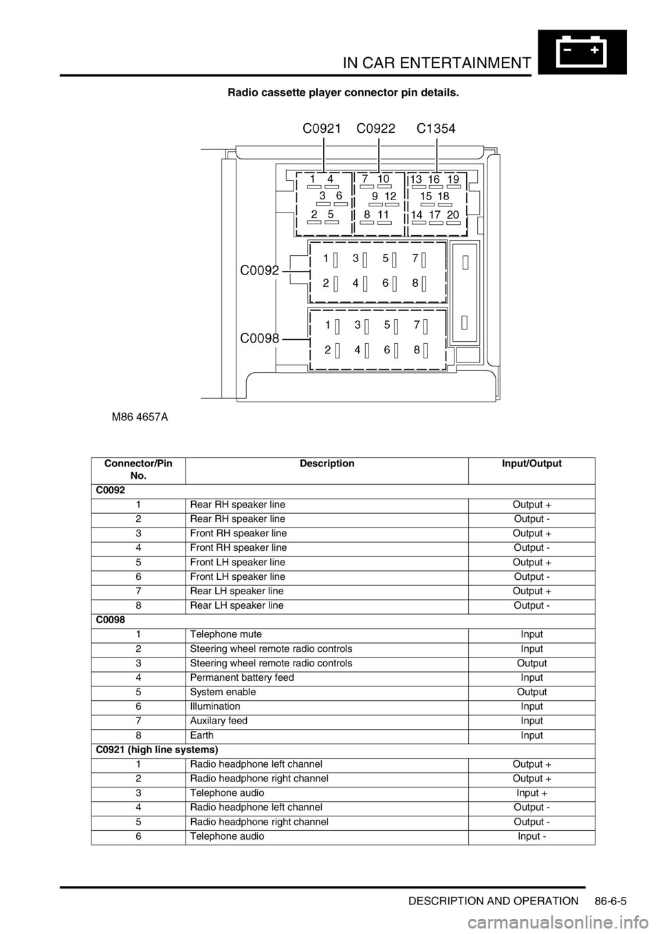
Radio cassette player connector pin details.
Connector/Pin
No.Description Input/Output
C0092
1 Rear RH speaker line Output +
2 Rear RH speaker line Output -
3 Front RH speaker line Output +
4 Front RH speaker line Output -
5 Front LH speaker line Output +
6 Front LH speaker line Output -
7 Rear LH speaker line Output +
8 Rear LH speaker line Output -
C0098
1 Telephone mute Input
2 Steering wheel remote radio controls Input
3 Steering wheel remote radio controls Output
4 Permanent battery feed Input
5 System enable Output
6 Illumination Input
7 Auxilary feed Input
8 Earth Input
C0921 (high line systems)
1 Radio headphone left channel Output +
2 Radio headphone right channel Output +
3 Telephone audio Input +
4 Radio headphone left channel Output -
5 Radio headphone right channel Output -
6 Telephone audio Input -