1999 LAND ROVER DISCOVERY rear view mirror
[x] Cancel search: rear view mirrorPage 31 of 1529

CONTENTS
28 CONTENTS
DRIVING AIDS .......................................................................................... 86-8-1
DESCRIPTION AND OPERATION
Park Distance Control – Component Location................................................................................ 86-8-1
Park Distance Control – Control Diagram....................................................................................... 86-8-2
Description ...................................................................................................................................... 86-8-4
Operation ........................................................................................................................................ 86-8-11
REPAIRS
Control unit (ECU) - park distance control (PDC) ........................................................................... 86-8-13
Sounder - parking aid rear ............................................................................................................. 86-8-14
Sensor - parking aid - rear - inner ................................................................................................... 86-8-15
Sensor - parking aid - rear - outer .................................................................................................. 86-8-16
NAVIGATION SYSTEM ............................................................................ 87-1
DESCRIPTION AND OPERATION
Harman/Becker Navigation System Component Location.............................................................. 87-1
Description ...................................................................................................................................... 87-2
DESCRIPTION AND OPERATION
CARiN III Navigation and Trafficmaster System Component Location........................................... 87-12
Description ...................................................................................................................................... 87-14
Operation ........................................................................................................................................ 87-20
REPAIRS
Interface electronic control unit (ECU) - remote control ................................................................. 87-29
Display unit .................................................................................................................................... 87-30
INSTRUMENTS ......................................................................................... 88-1
DESCRIPTION AND OPERATION
Instrument pack .............................................................................................................................. 88-1
Instrument component location - Engine compartment / underneath vehicle ................................. 88-2
Instrument component location - Passenger compartment ............................................................ 88-3
Instrument block diagram ............................................................................................................... 88-4
Description ...................................................................................................................................... 88-5
Interior rear view mirror with compass (where fitted) ..................................................................... 88-42
REPAIRS
Clock ............................................................................................................................................... 88-45
Instrument pack ............................................................................................................................ 88-45
Page 762 of 1529

FRONT SUSPENSION
DESCRIPTION AND OPERATION 60-17
The actuator has a forked end which locates on the bush in the short arm and is secured with a bolt and nut. The
piston rod of the actuator locates through a hole in a cast boss on the long arm which is fitted with a special bush. A
shoulder on the piston rod seats in a hole in the bush and a locknut on the end of the piston rod secures the rod to
the long arm and bush.
The front torsion bar is attached to the front chassis cross member. Two rubber bushes are fitted to the torsion bar
and are located in clamp plates. The clamp plates are located in slots in the cross member and secured with bolts.
The rear torsion bar is attached to the tubular cross member at the rear section of the chassis. Two rubber bushes
are fitted to the torsion bar and are located in clamp plates. The clamp plates are located in fabricated brackets
attached to the tubular cross-member and secured with bolts.
Two anti-roll bar links are mounted on brackets on the front and rear axles. Each anti-roll bar link is fitted with a
spherical bearing at each end. One bearing is attached to the link at a 90° angle. The threaded shank of the bearing
is located through a hole in a bracket on the axle and secured with a locknut; a washer is installed on the threaded
shank between the bearing and the bracket. The second spherical bearing is attached in-line with the link and locates
in the torsion bar on the left hand side and the long arm on the right hand side. The front anti-roll bar links are longer
than the rear links and are not interchangeable.
Accelerometers
Two accelerometers are used for the ACE system. The upper accelerometer is mounted on a bracket, behind the
headlining adjacent to the rear view mirror and the sunroof ECU. The lower accelerometer is located on a bracket on
the inner sill panel under the RH front floor.
The lower accelerometer is the primary sensor used to measure lateral acceleration of the vehicle for roll control. The
upper accelerometer is used by the ECU for roll correction and fault detection in conjunction with the lower
accelerometer.
Each accelerometer is a solid state capacitive acceleration sensor and operates on a 5 V supply from the ECU. The
upper and lower sensors can measure acceleration in the range of ± 1.10 g and return an output to the ECU of
between 0.5 and 4.5 V.
Failures of an accelerometer are recorded by the ECU and can be retrieved using TestBook. A special tool is required
to remove and replace a sensor in the bracket.
Page 1043 of 1529

SUNROOF
76-6-12 DESCRIPTION AND OPERATION
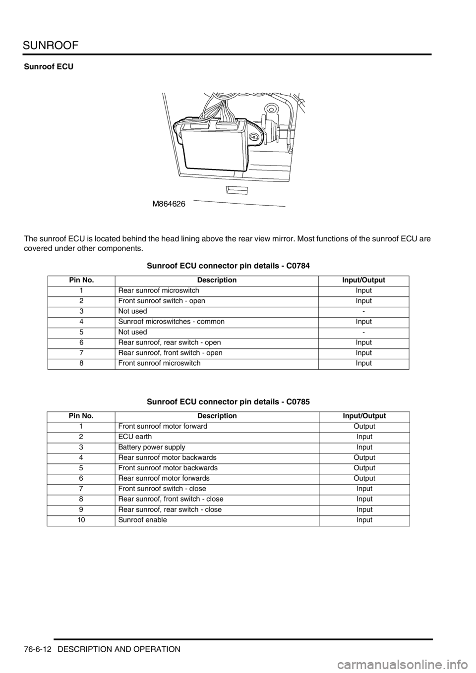
Sunroof ECU
The sunroof ECU is located behind the head lining above the rear view mirror. Most functions of the sunroof ECU are
covered under other components.
Sunroof ECU connector pin details - C0784
Sunroof ECU connector pin details - C0785
Pin No. Description Input/Output
1 Rear sunroof microswitch Input
2 Front sunroof switch - open Input
3 Not used -
4 Sunroof microswitches - common Input
5 Not used -
6 Rear sunroof, rear switch - open Input
7 Rear sunroof, front switch - open Input
8 Front sunroof microswitch Input
Pin No. Description Input/Output
1 Front sunroof motor forward Output
2 ECU earth Input
3 Battery power supply Input
4 Rear sunroof motor backwards Output
5 Front sunroof motor backwards Output
6 Rear sunroof motor forwards Output
7 Front sunroof switch - close Input
8 Rear sunroof, front switch - close Input
9 Rear sunroof, rear switch - close Input
10 Sunroof enable Input
Page 1470 of 1529

NAVIGATION SYSTEM
DESCRIPTION AND OPERATION 87-17
GPS Antenna
The GPS antenna is installed on the rear of the roof, on the vehicle centreline. A diplexer unit on the underside of the
GPS antenna amplifies the radio signals received from the GPS satellites and transmits them through a co-axial cable
to the navigation computer for processing.
Display Unit
The display unit is integrated into the front stowage pocket, above the rear view mirror. The display unit is a colour
Liquid Crystal Display (LCD) that shows the programming menus, route guidance and traffic information. The display
illumination level automatically dims for night time viewing when the exterior lights are switched on.
Page 1525 of 1529

INSTRUMENTS
88-42 DESCRIPTION AND OPERATION
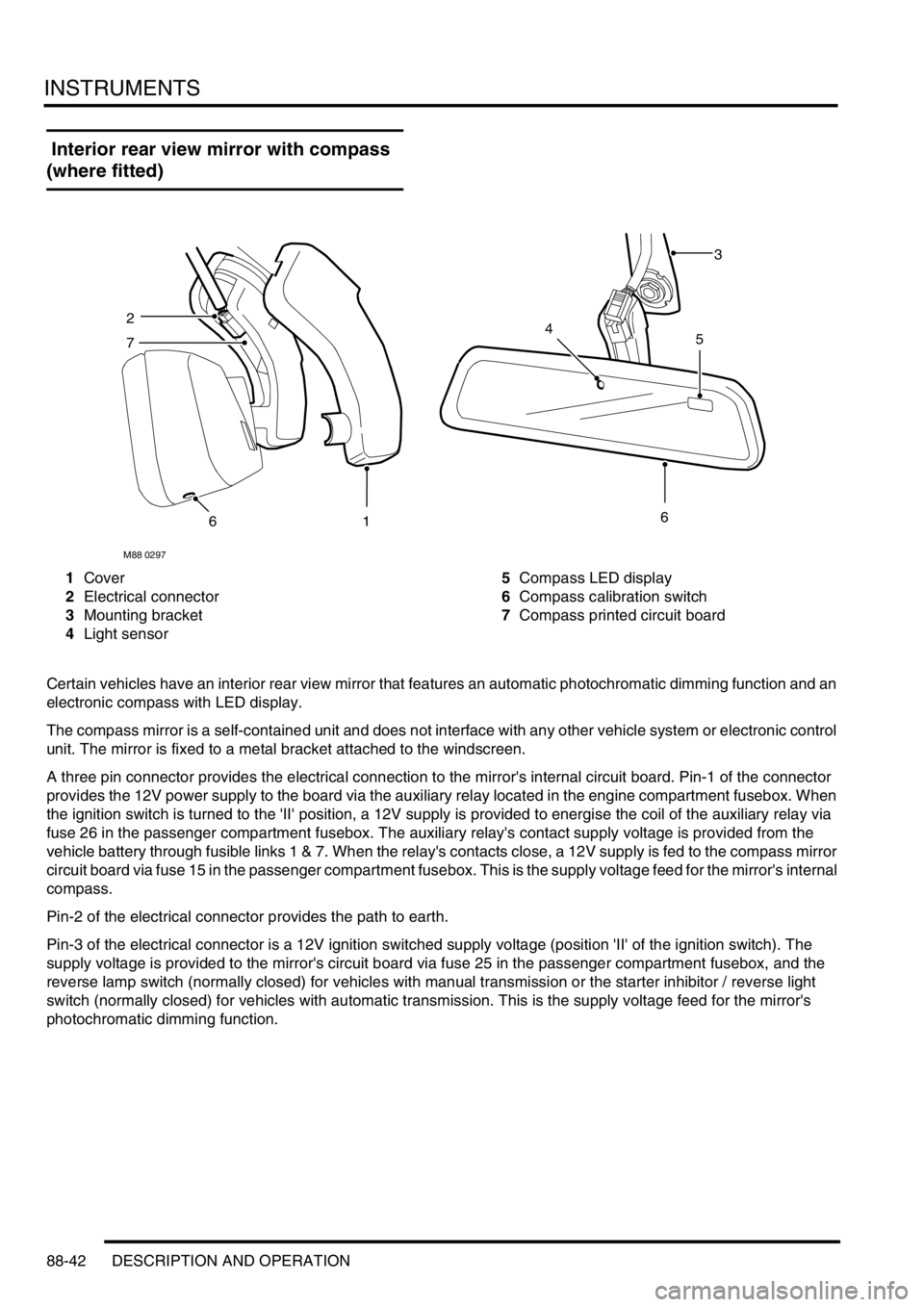
Interior rear view mirror with compass
(where fitted)
1Cover
2Electrical connector
3Mounting bracket
4Light sensor5Compass LED display
6Compass calibration switch
7Compass printed circuit board
Certain vehicles have an interior rear view mirror that features an automatic photochromatic dimming function and an
electronic compass with LED display.
The compass mirror is a self-contained unit and does not interface with any other vehicle system or electronic control
unit. The mirror is fixed to a metal bracket attached to the windscreen.
A three pin connector provides the electrical connection to the mirror's internal circuit board. Pin-1 of the connector
provides the 12V power supply to the board via the auxiliary relay located in the engine compartment fusebox. When
the ignition switch is turned to the 'II' position, a 12V supply is provided to energise the coil of the auxiliary relay via
fuse 26 in the passenger compartment fusebox. The auxiliary relay's contact supply voltage is provided from the
vehicle battery through fusible links 1 & 7. When the relay's contacts close, a 12V supply is fed to the compass mirror
circuit board via fuse 15 in the passenger compartment fusebox. This is the supply voltage feed for the mirror's internal
compass.
Pin-2 of the electrical connector provides the path to earth.
Pin-3 of the electrical connector is a 12V ignition switched supply voltage (position 'II' of the ignition switch). The
supply voltage is provided to the mirror's circuit board via fuse 25 in the passenger compartment fusebox, and the
reverse lamp switch (normally closed) for vehicles with manual transmission or the starter inhibitor / reverse light
switch (normally closed) for vehicles with automatic transmission. This is the supply voltage feed for the mirror's
photochromatic dimming function.
M88 0297
3
2
7
616
45